Monthly Archives: December 2017

//December

Very nice but rotten

Back in November I covered a repair to a Southerly that had been T-boned.
Well the job was finished and I was just tidying up when the owner asked me to see if I could locate his fluxgate compass.
I stuck my head in various lockers and other likely places it might have been fitted.
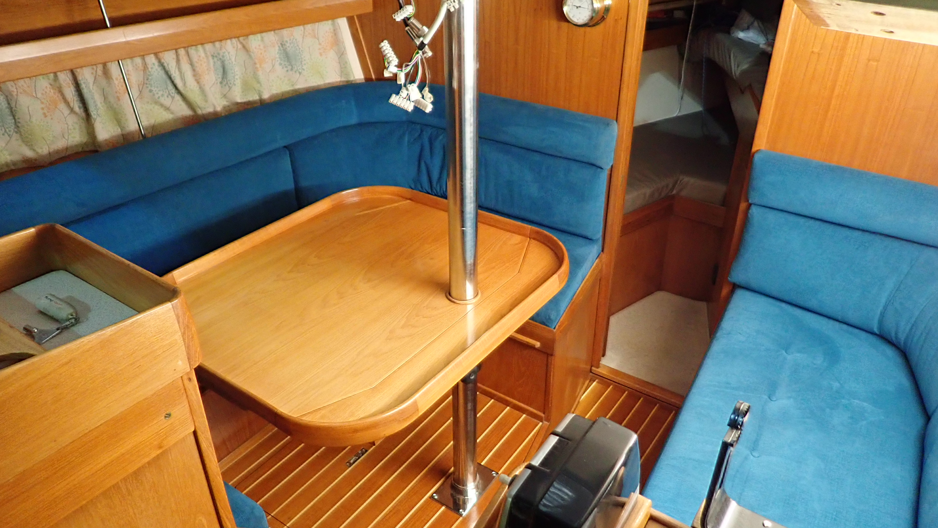
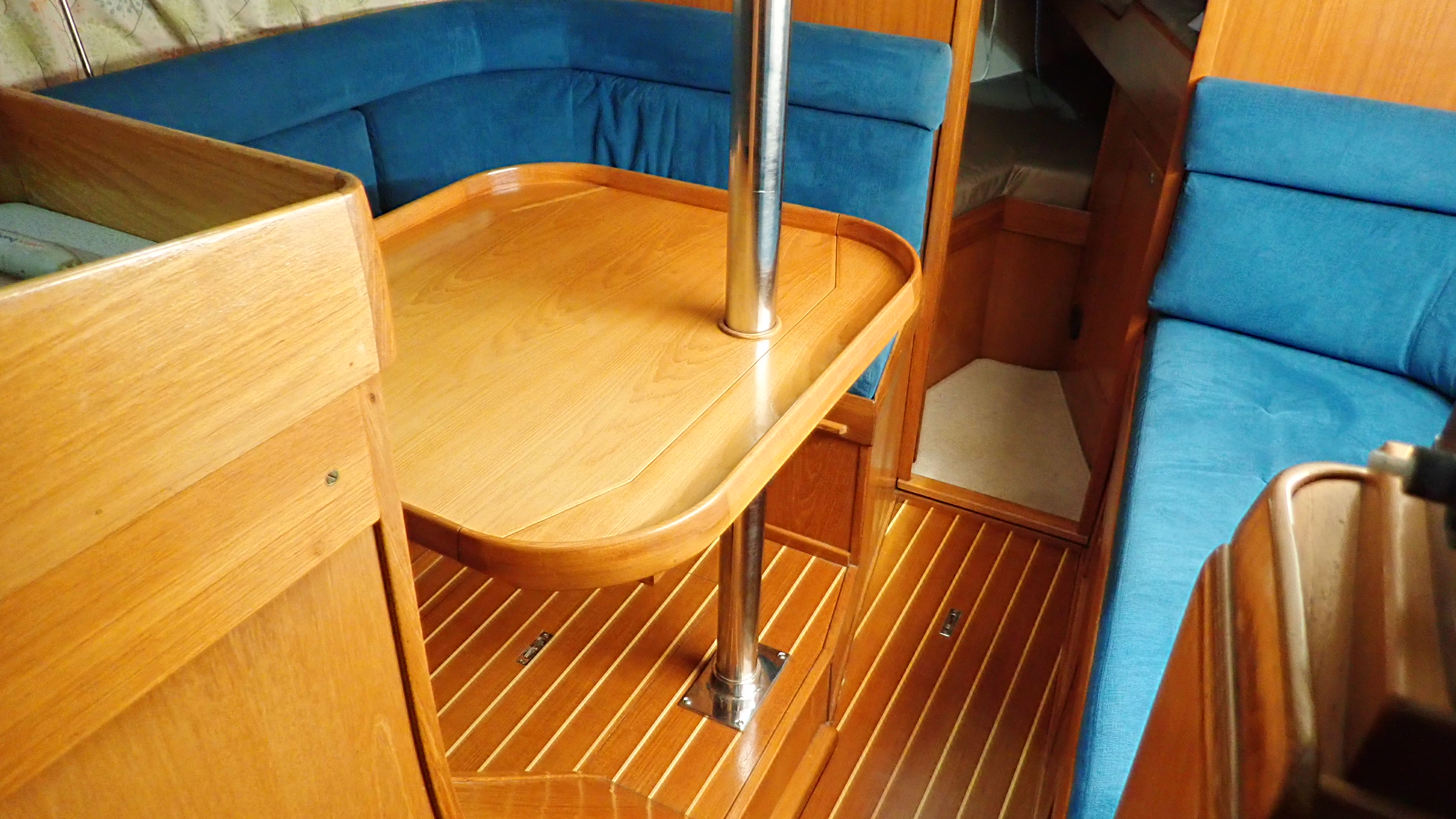
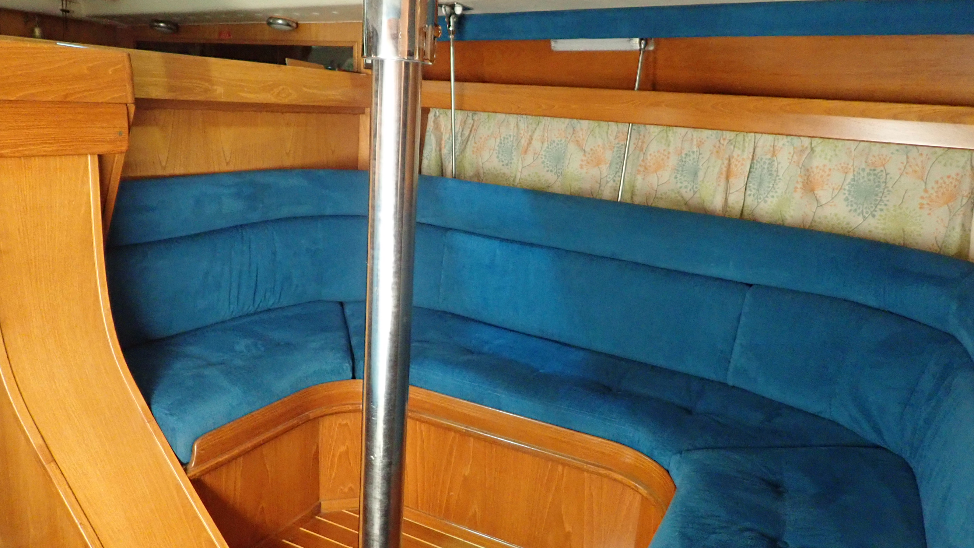
This 1999 boat is in very good order, all the varnish, trim, flooring and upholstery looking like is on a boat a couple of years old, so I really wasn’t looking for trouble.

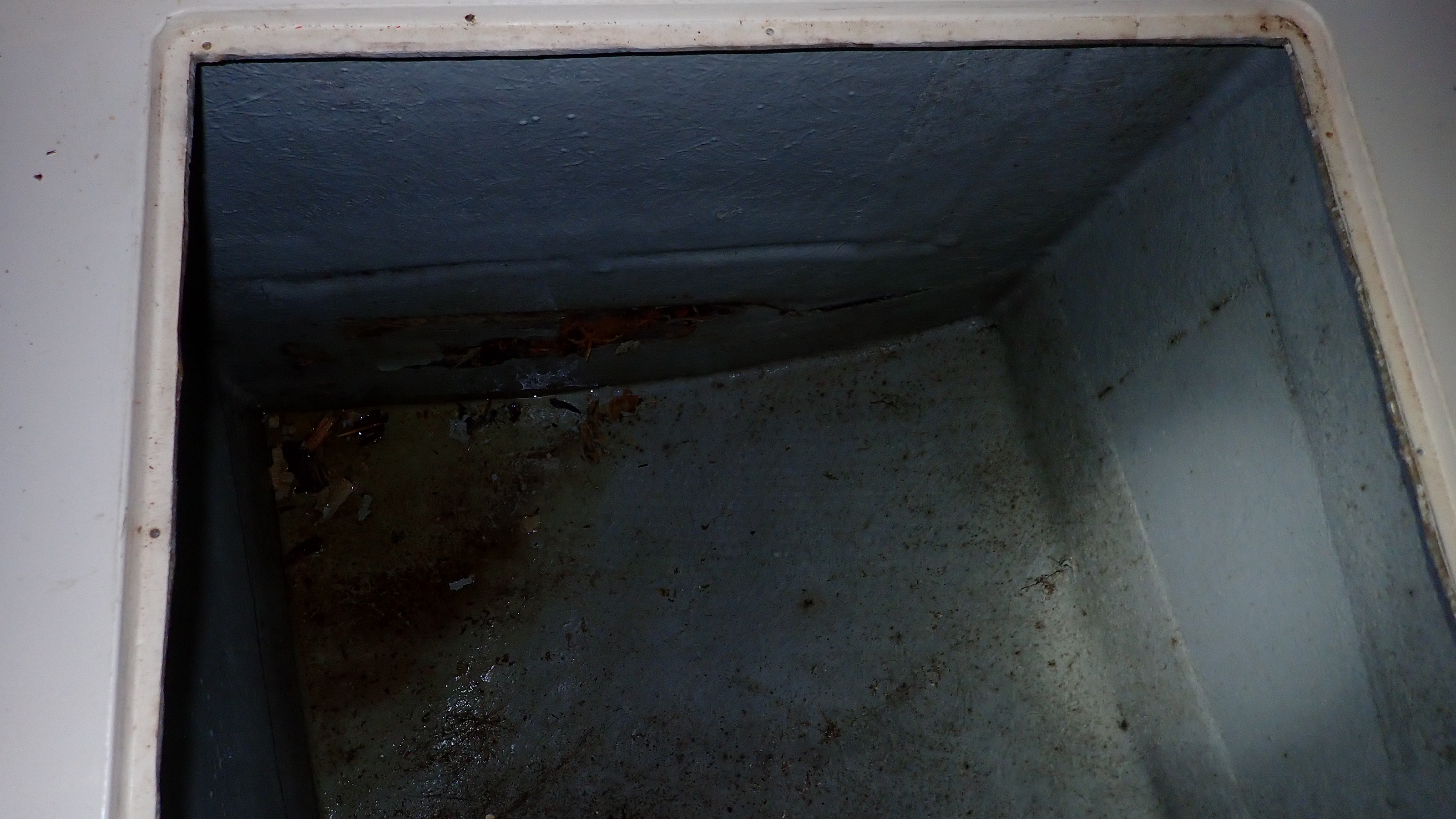
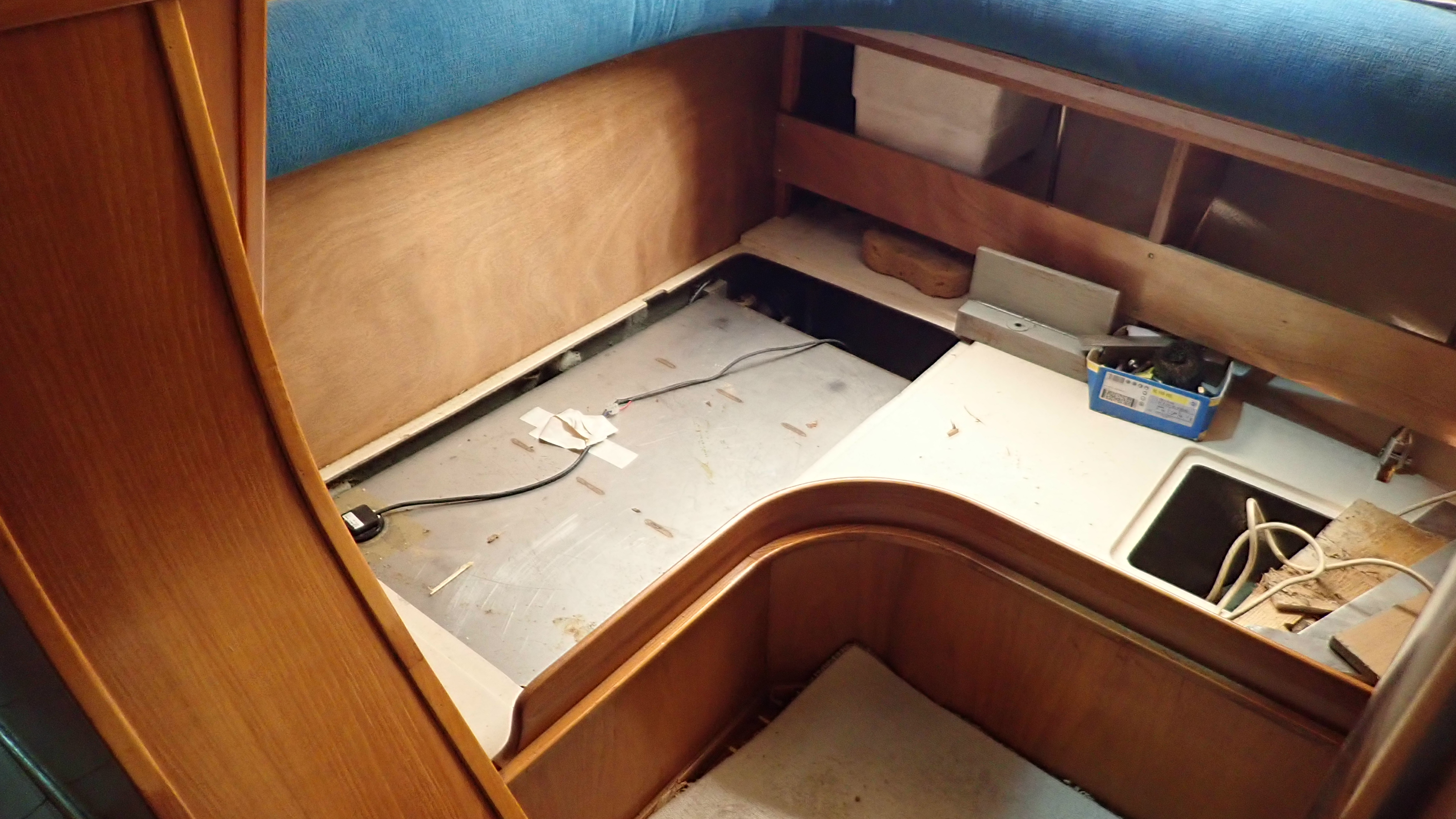
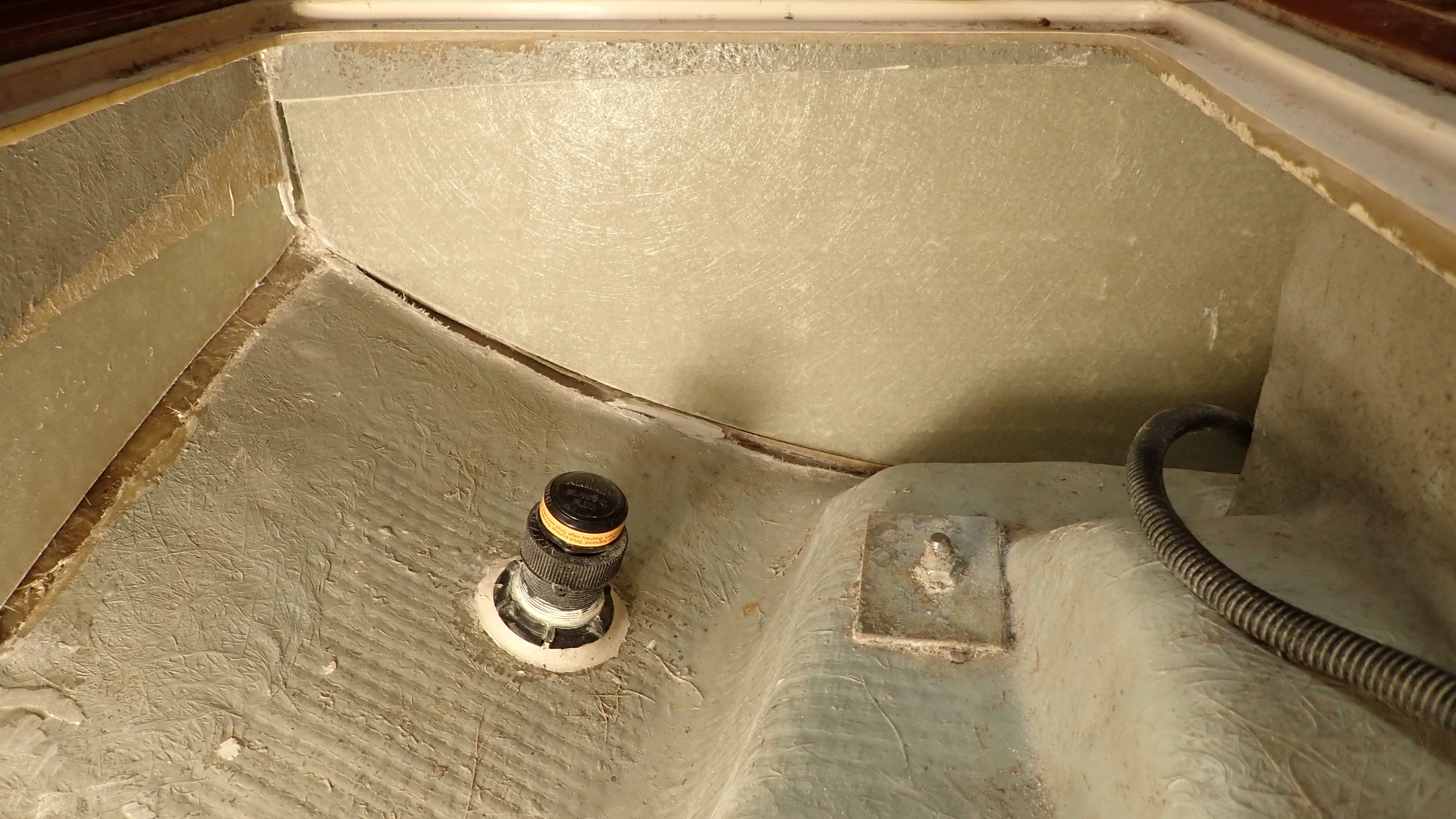
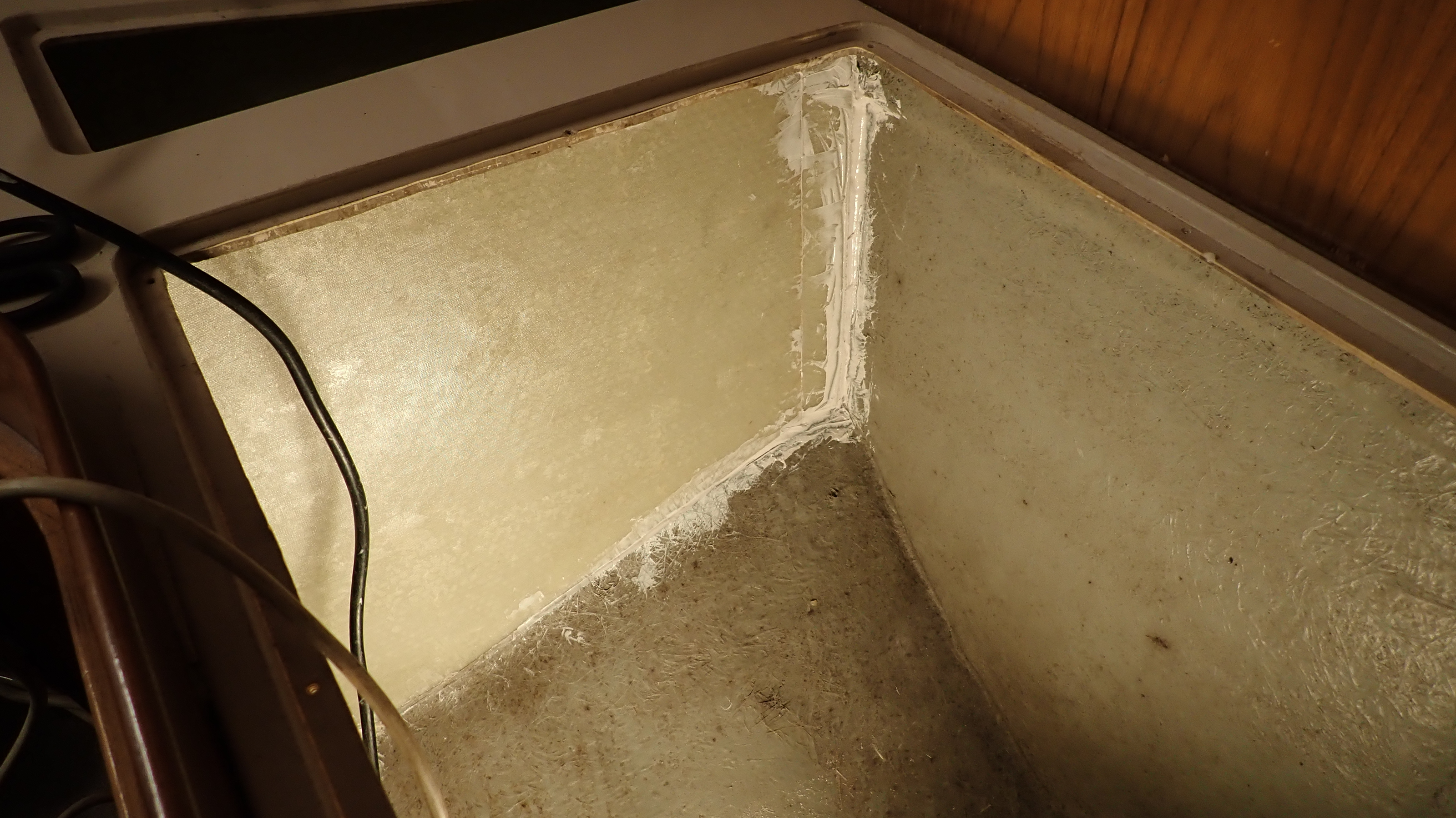
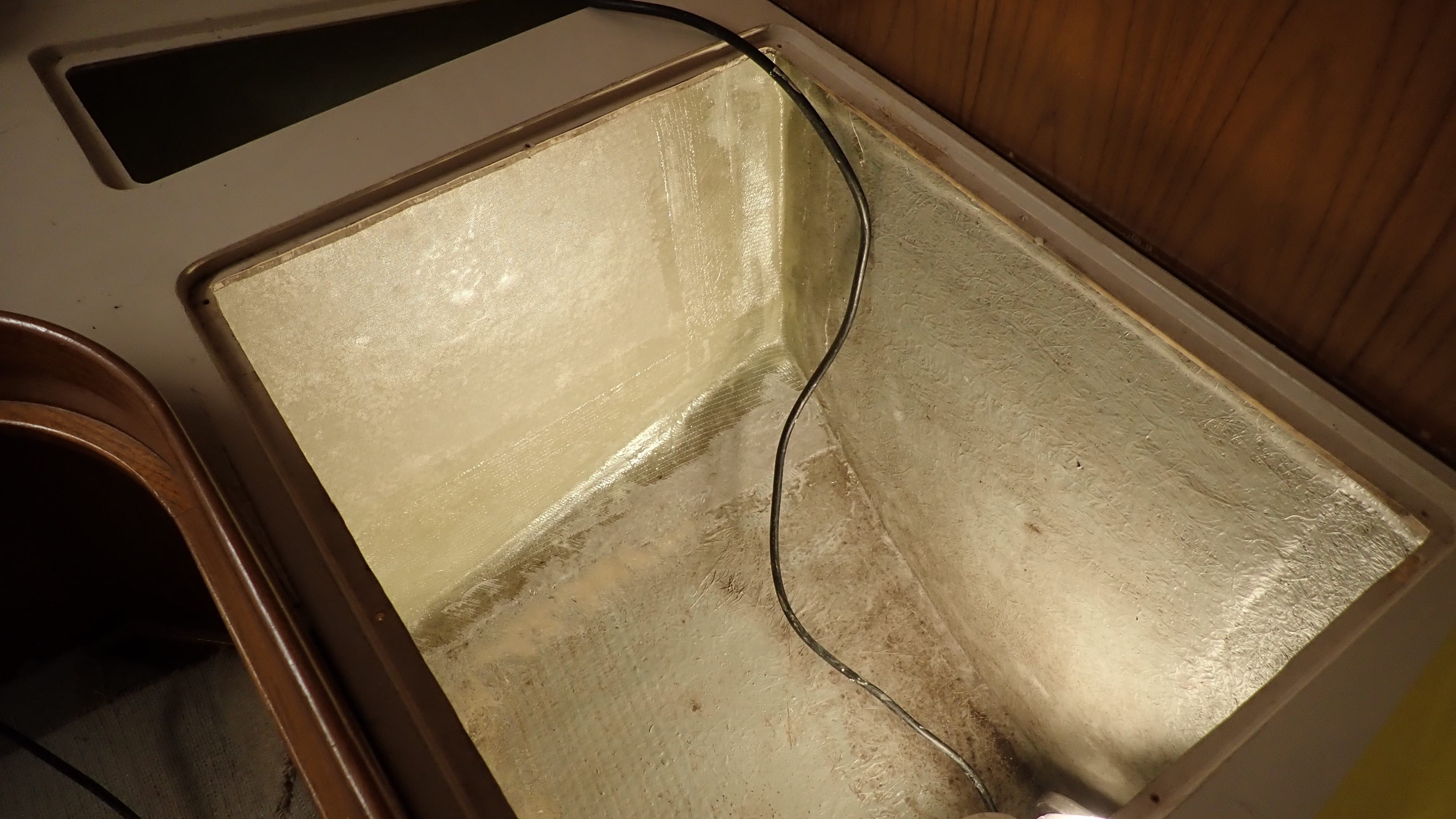
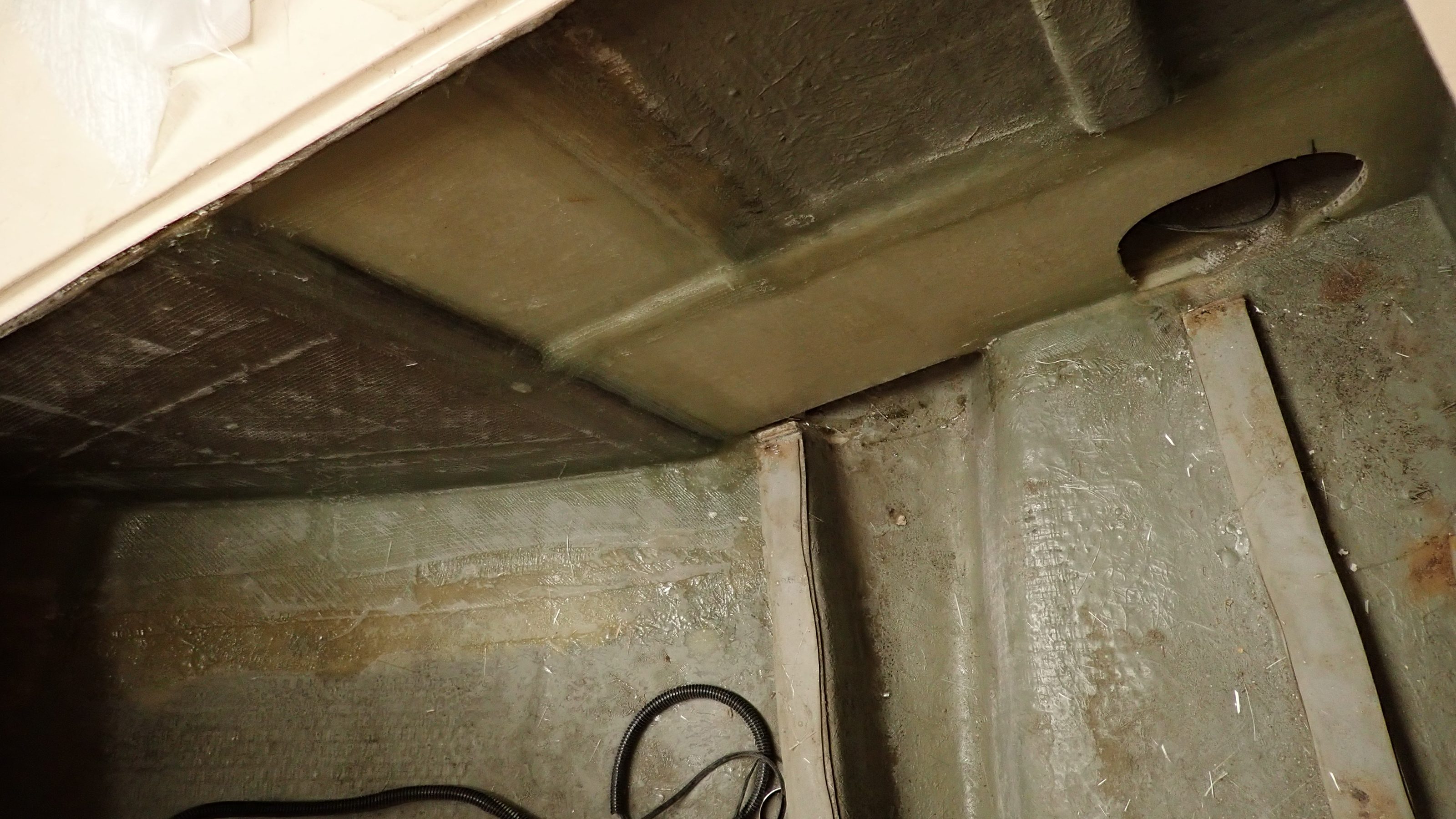
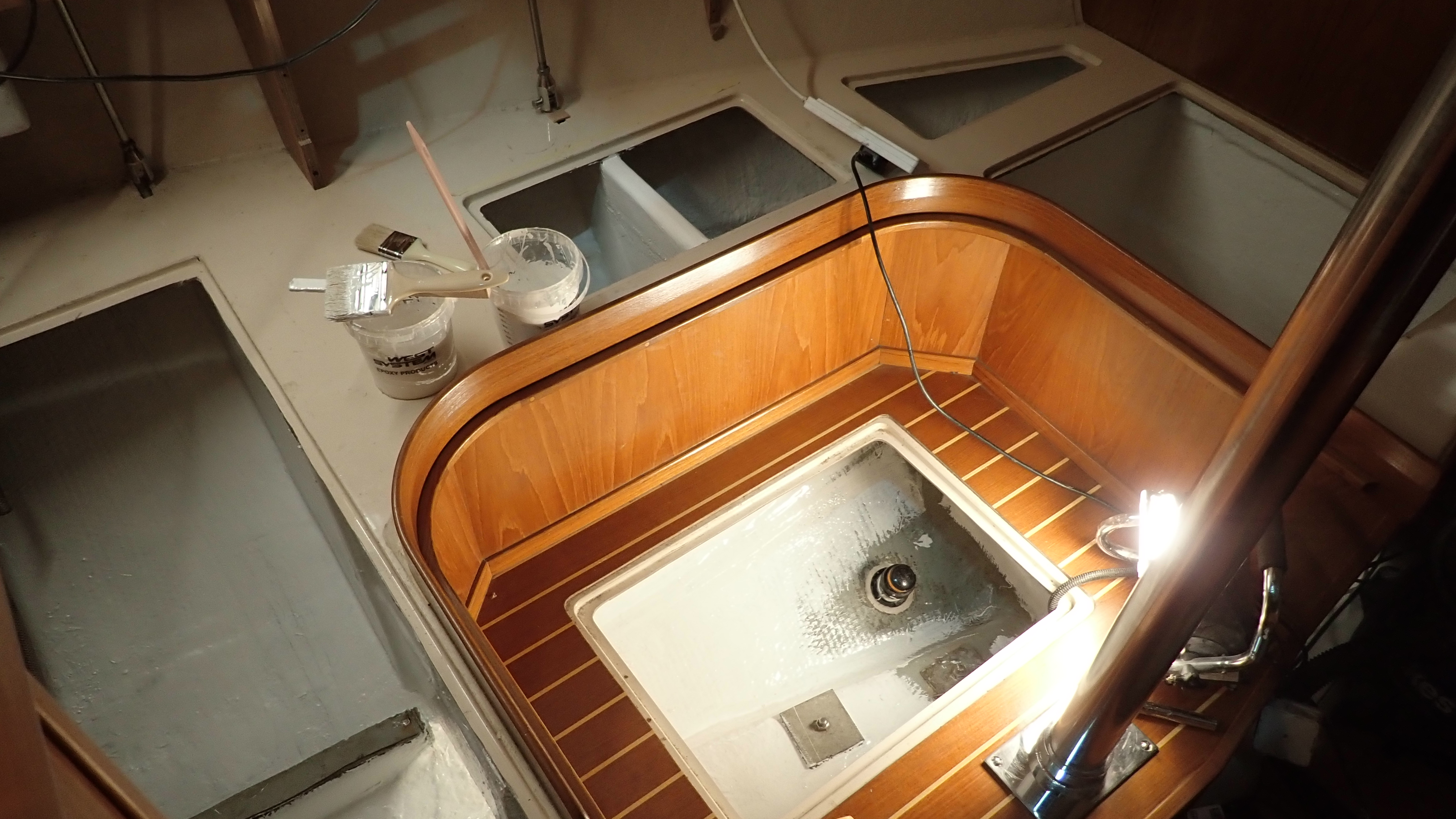
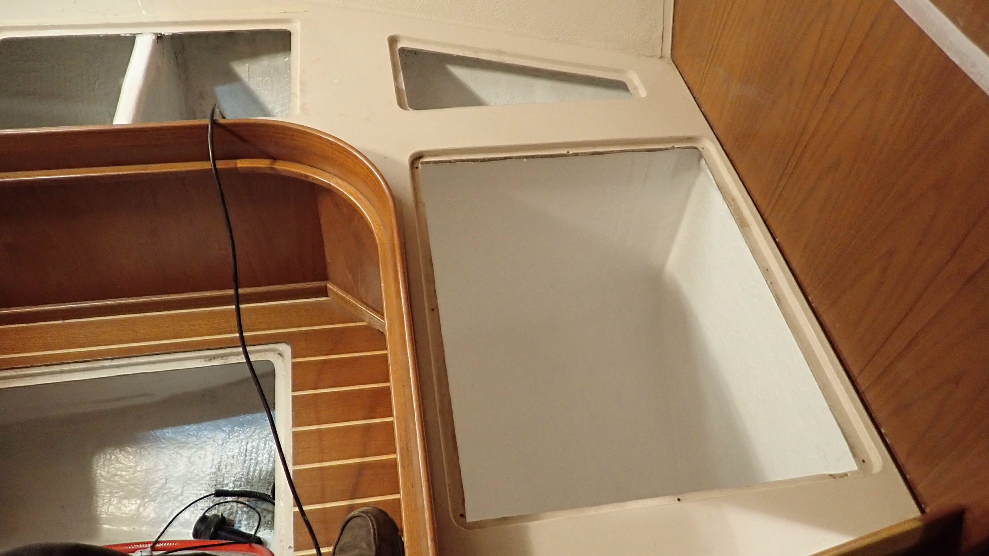
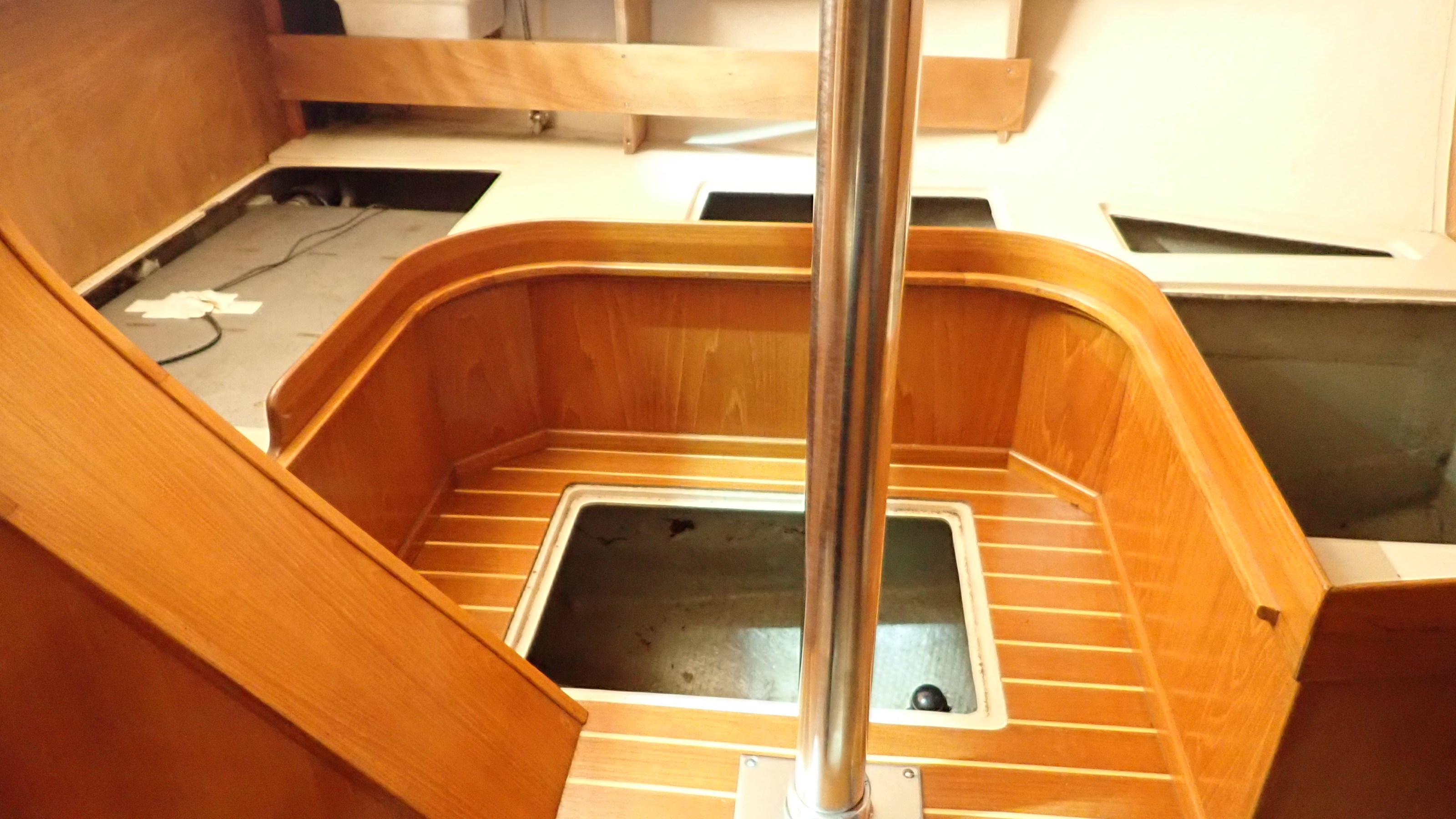
The following shots were taken after I’d finished the job but they could have equally been taken before I started.


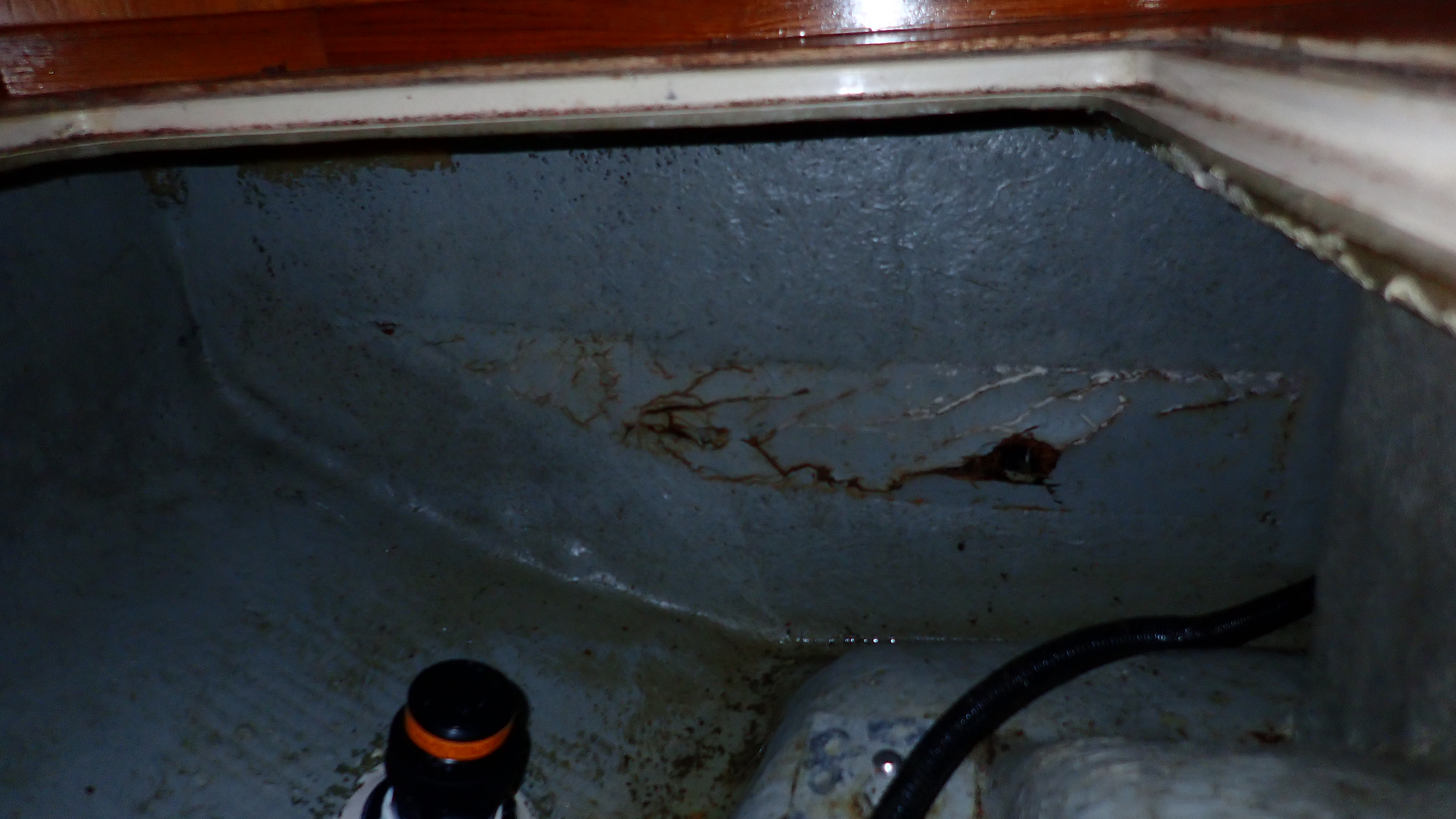
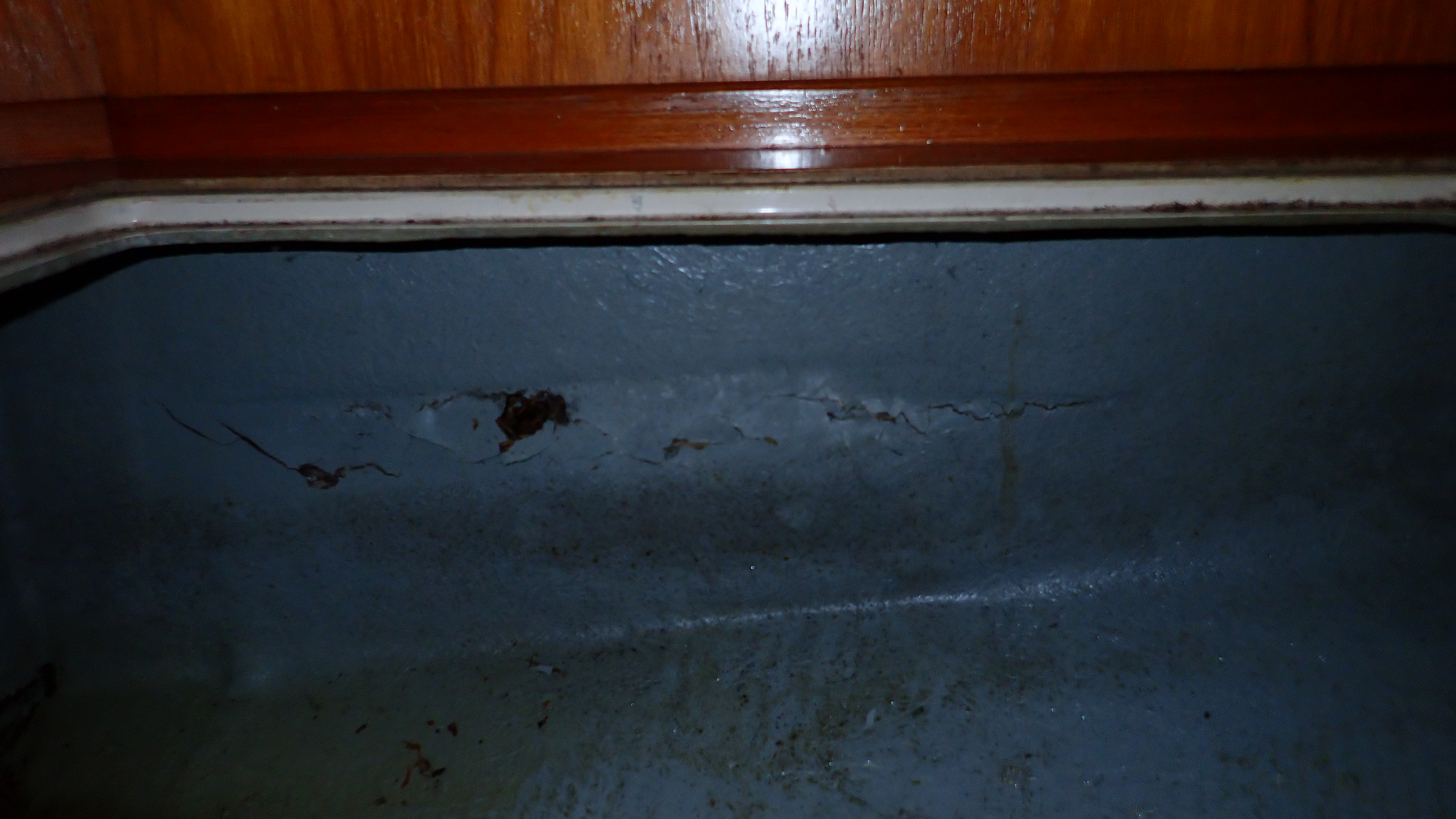
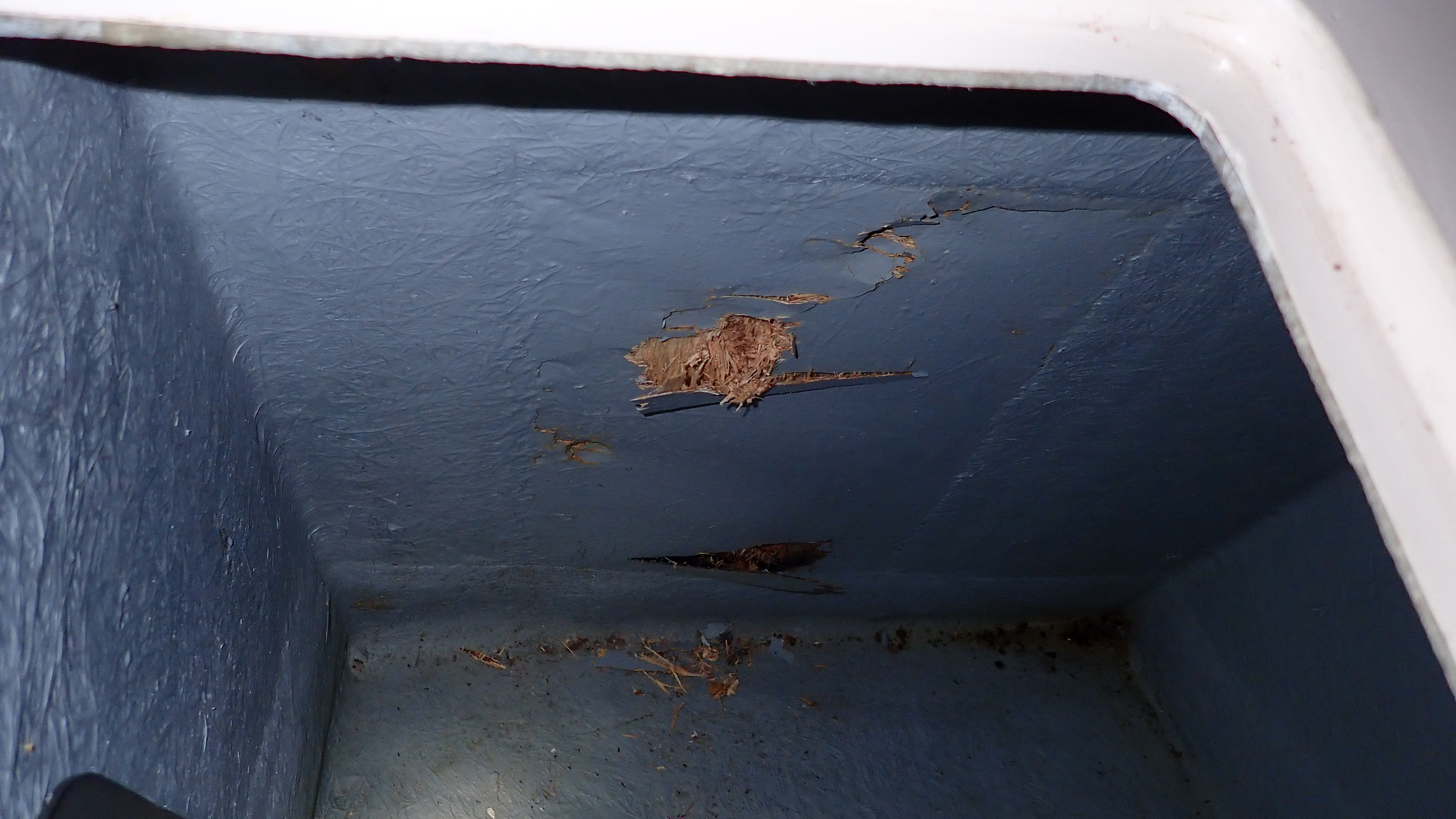
When I checked under the raised seating area I noticed that the gelcoat wash that had been put on the plywood bulkheads had cracked in a couple of places.
I poked one of these marks with my finger and I was frankly astonished that my finger went right through the plywood.
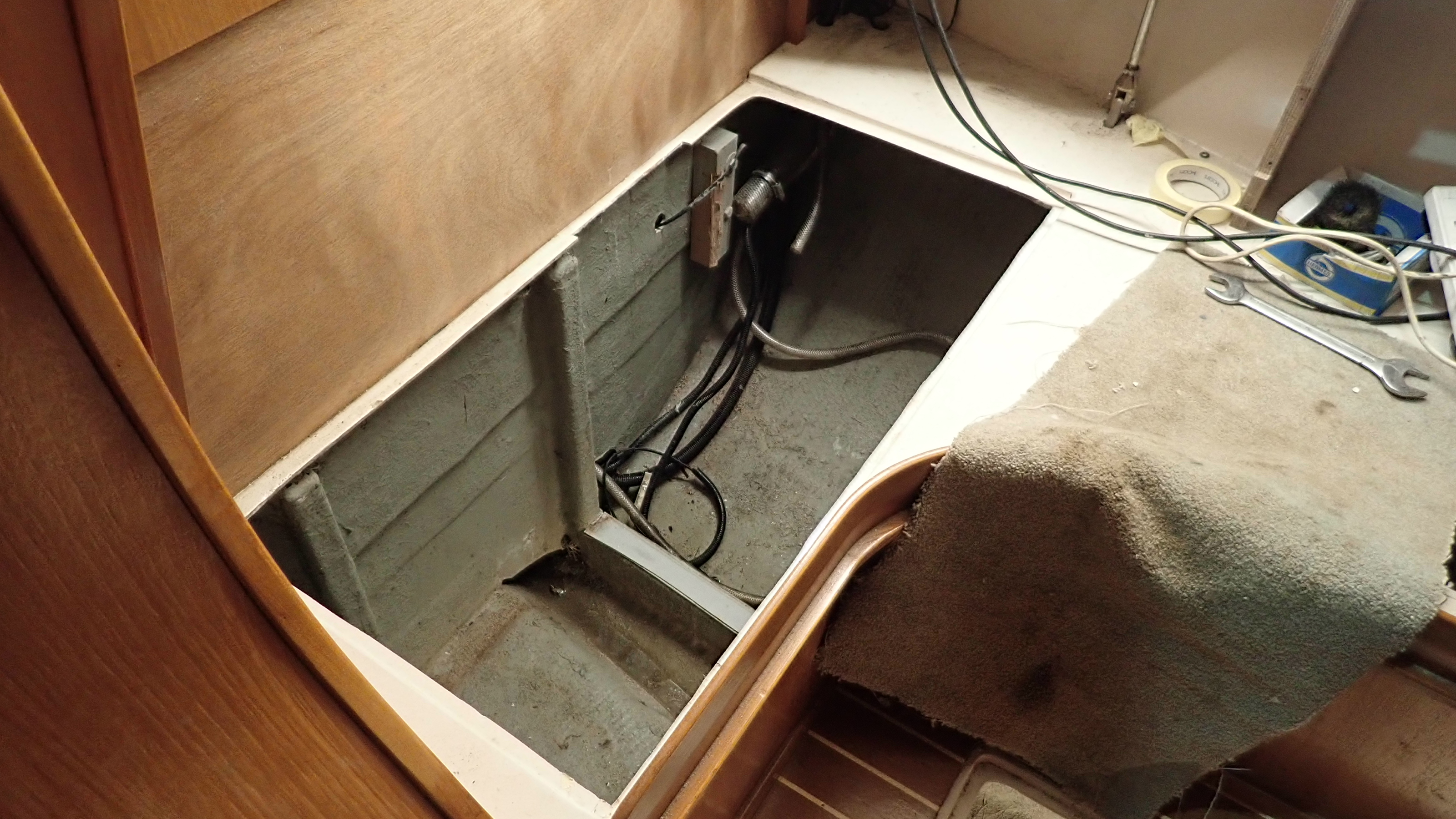
Under this raised seating area is long length of plywood that stretches from the water tank, in front of the galley area, to the main lateral bulkhead splitting the saloon from the forward cabin.
Off this longitudinal bulkhead there are two sheathed  plywood  locker sides and also the two port side chain plate knees.
It appears that when the builder fitted this plywood structure, they simply butted each section of plywood together, before glassing it in place and then sheathing it.
However in a couple of places, on the less important locker sides, they didn’t sheath the panels entirely, leaving an area around 4″ by 12″ in the middle of the panel that just had a coating of gelcoat.

Not much to look at really and easy to ignore.

I didn’t expect to be able to push my finger through though.

After a few minutes water started to drain out of the finger hole into the bottom of the locker.

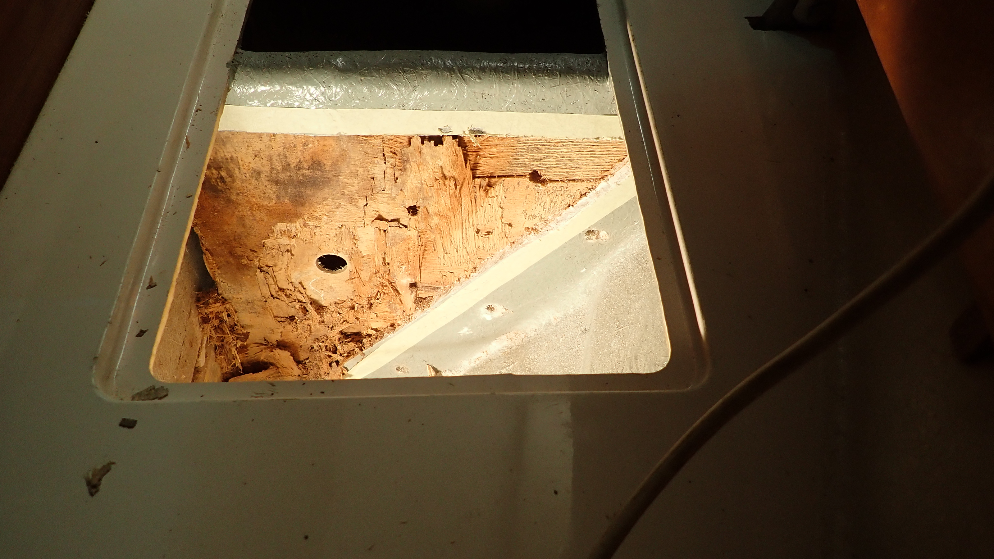
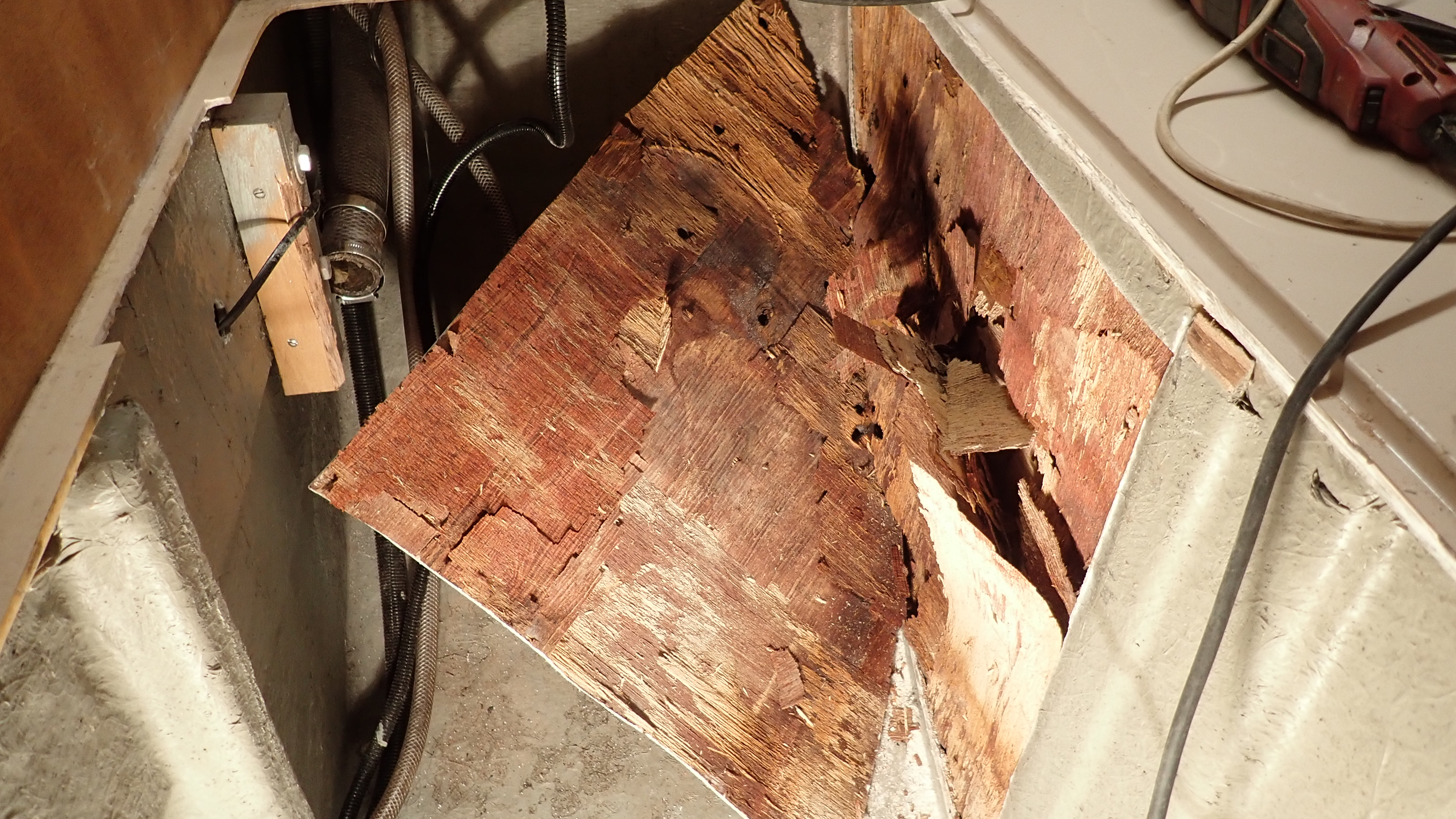
I knew we were in trouble when an area at least two feet above the bilge was obviously rotten.

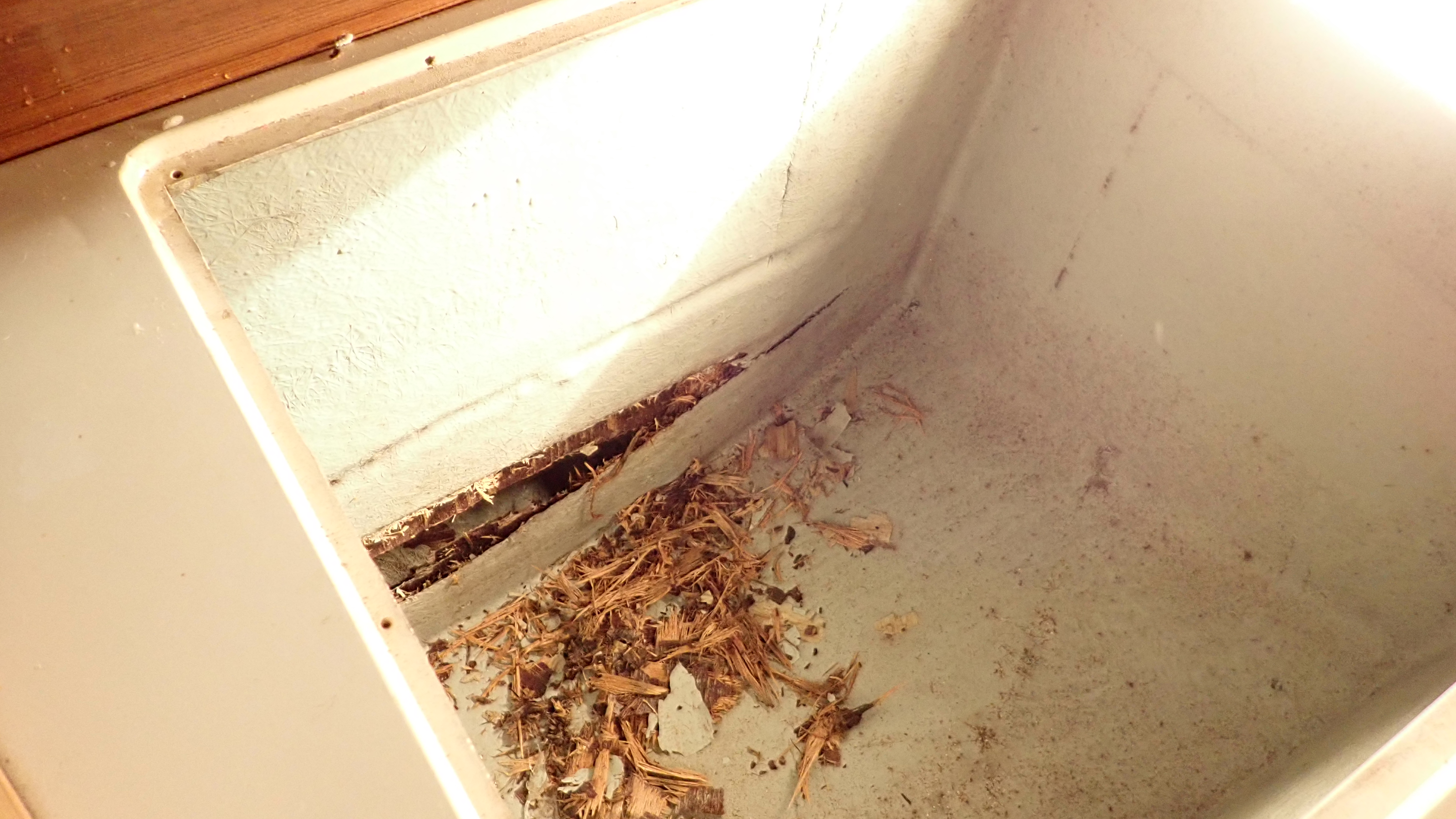
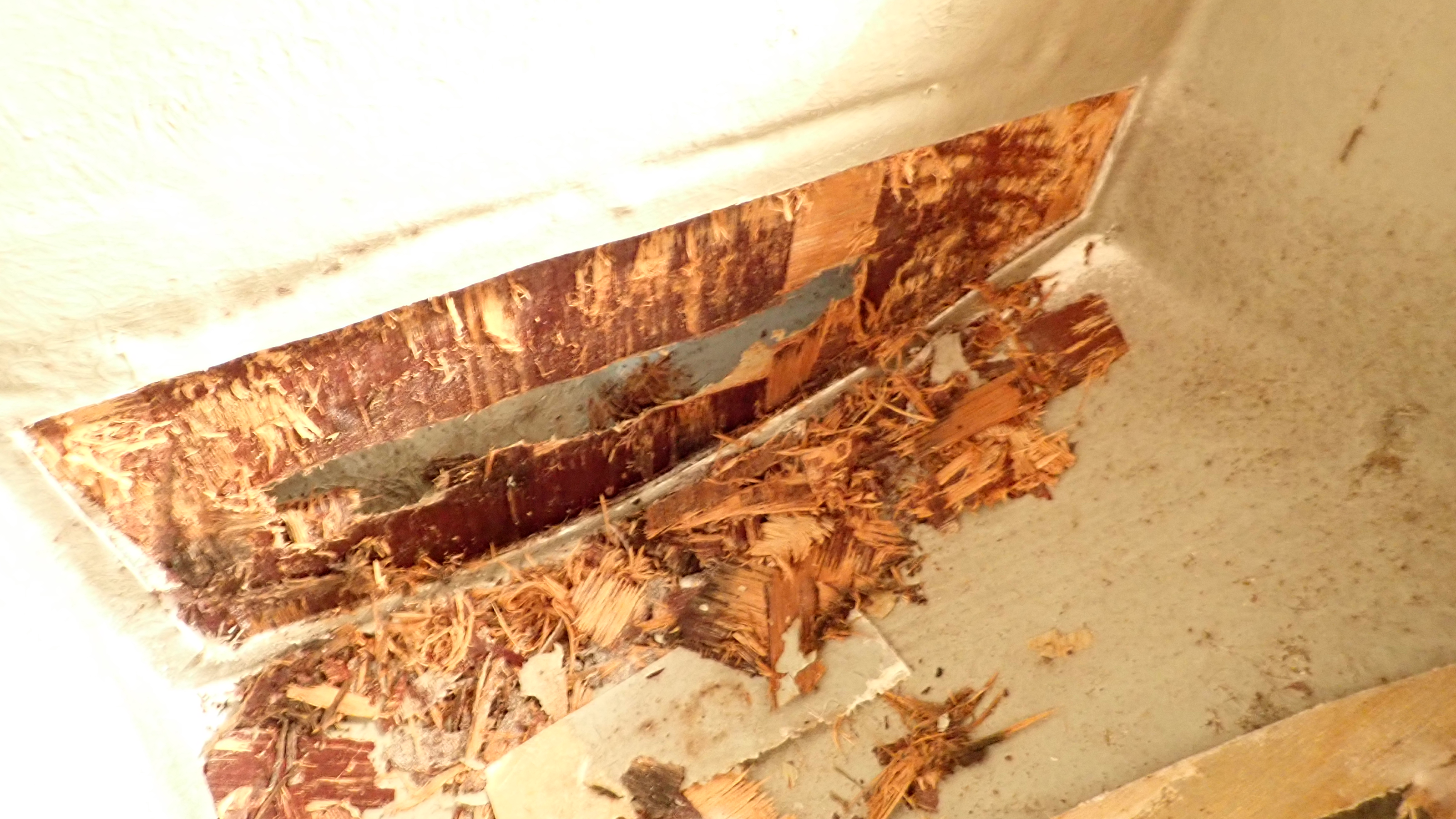
I poked a little more at the forward locker side and it was found to be water logged mush, though strangely no smell at all.
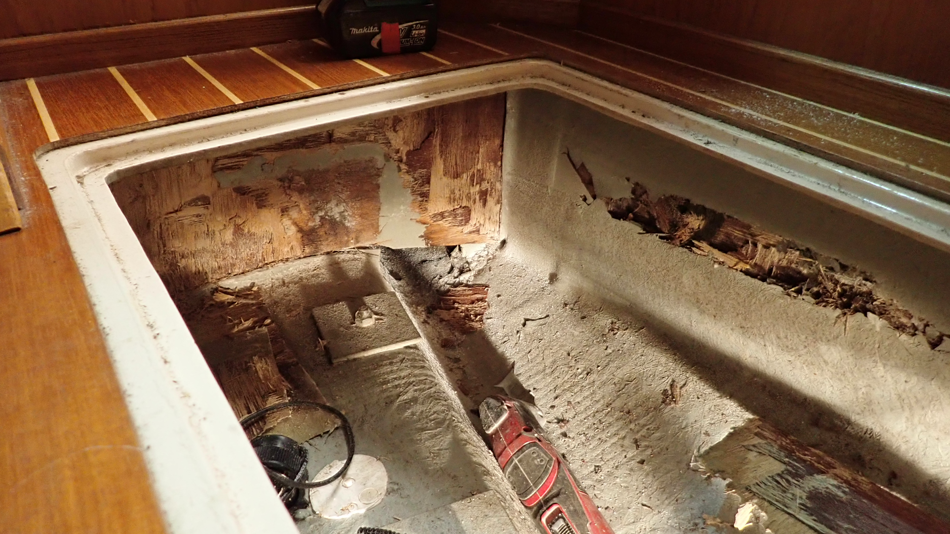
With a multitool I cut out the glass tabling around the panel and scooped out all the soaked rotten wood.
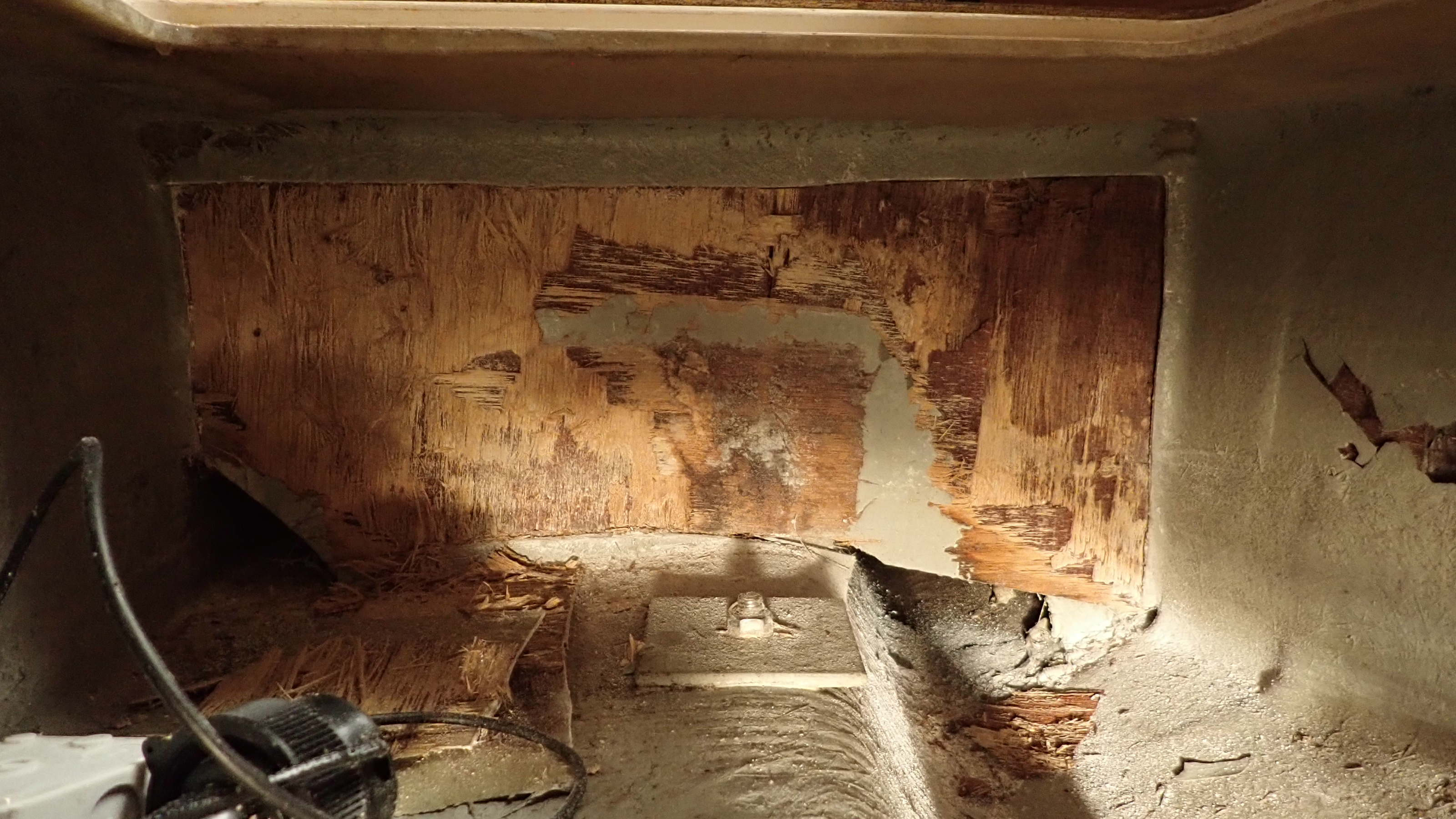
I then turned my attention to the longitudinal bulkhead and this was slightly dryer but was still wet and crumbled in my hand.
I followed this process gradually working my way round the structure removing all the rotten wood.

Things got a bit more serious when looking at the main chainplate knees.
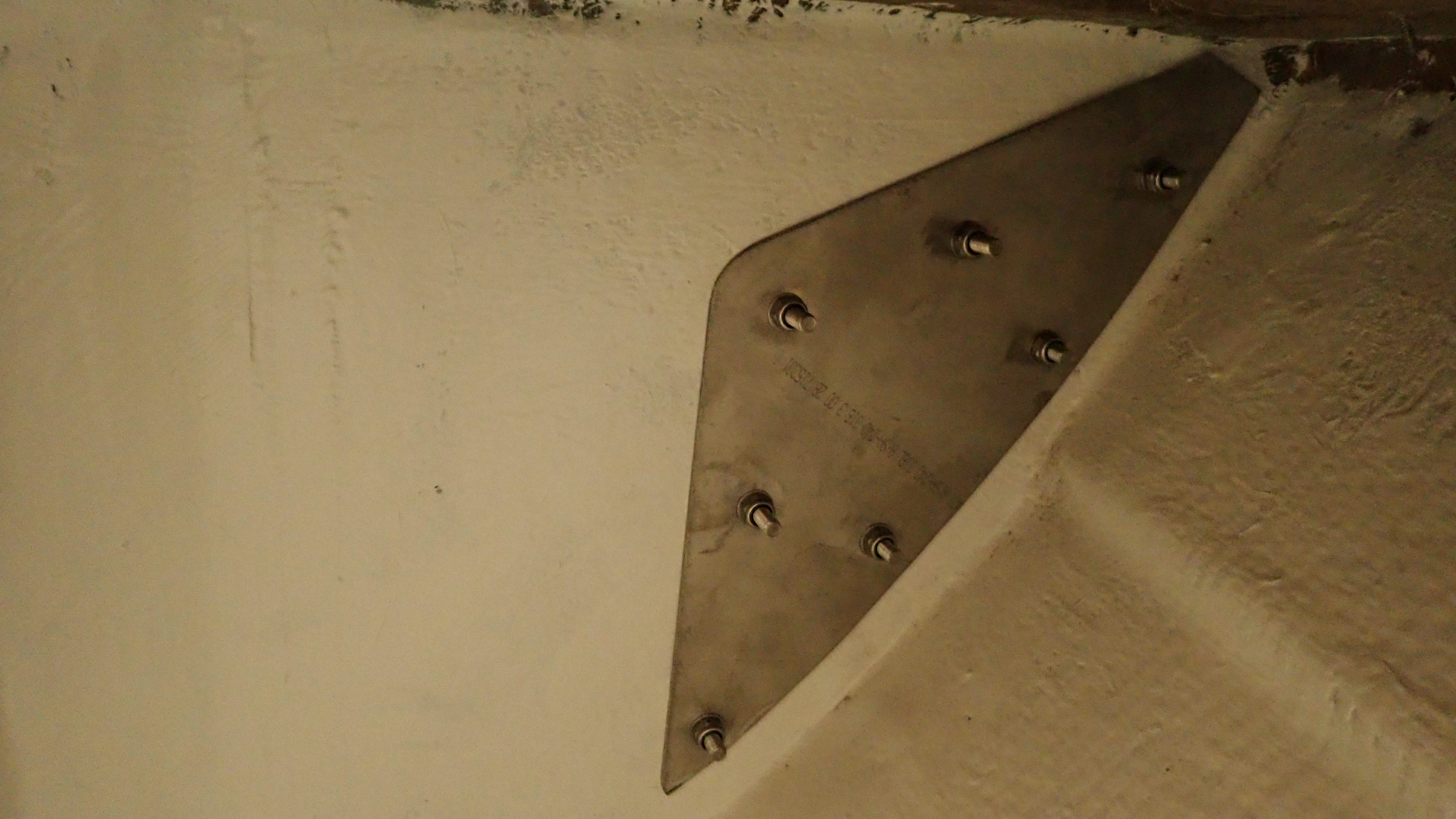
Whilst from the outside the knees looked fine, if you look at the photo carefully you can see the bolts are at a slight angle.
In fact four or five of the nuts were only finger tight.
With the chainplate bolts removed we could inspect the backing plate, which surprised us as it was made from aluminum plate rather than 316 Stainless.
All the holes had elongated showing that the plate had raised under load by around 30mm.
Using a hole cutter I drilled out an exploratory 30mm hole through the sheathing to check the Knee core and found nothing but damp dust.
After cutting away the side of the knee it was obvious that the knees would need rebuilding and also the realization that the rig could have come down at any time.
The rest of the interior wood is in excellent condition, as it was isolated from the supporting structure having been fitted as an independent module at a later stage of the build.
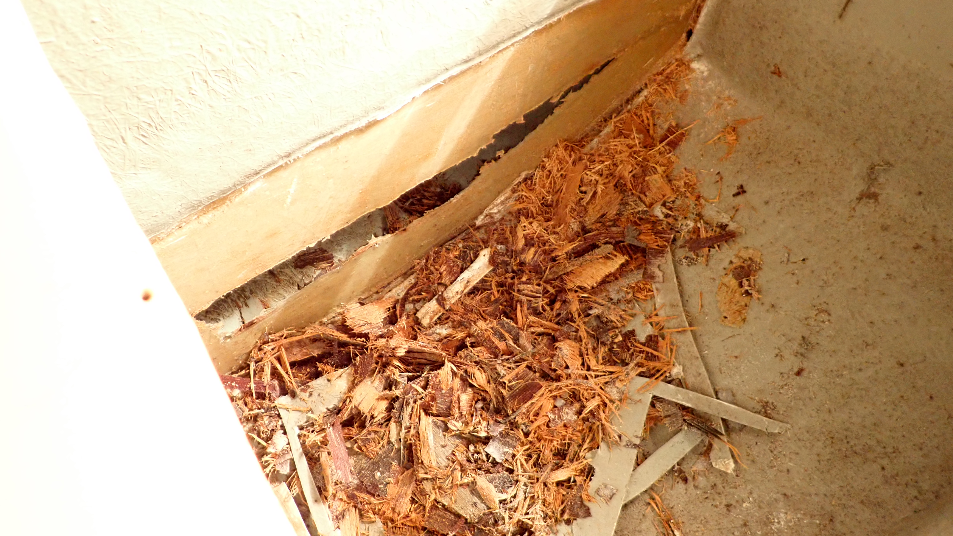
In some ways life was made easy in that the wood was in such poor condition that it simply fell away without much effort at all.
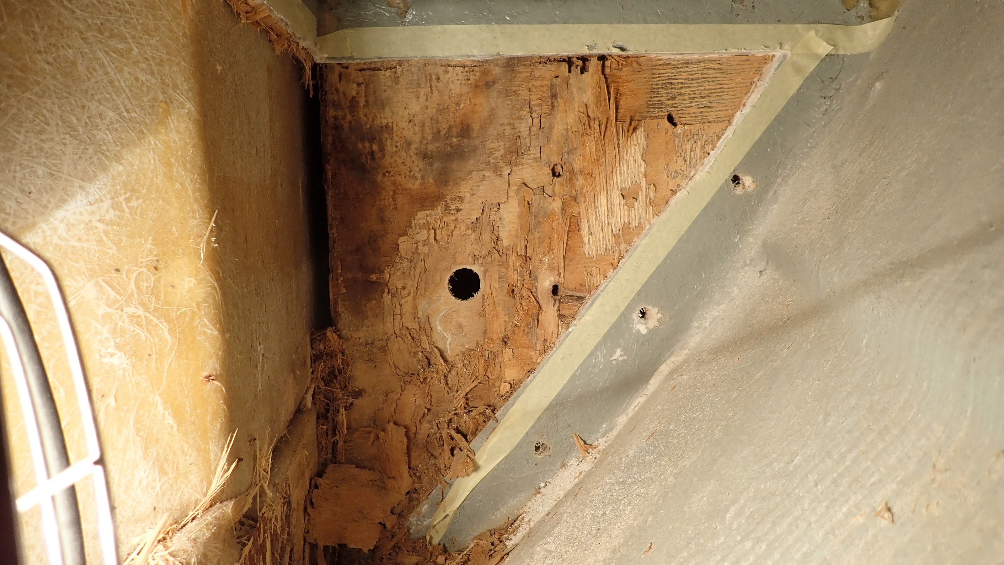
After cutting a 30mm core and finding nothing solid I decided to cut one side of the main chain plate knee out.
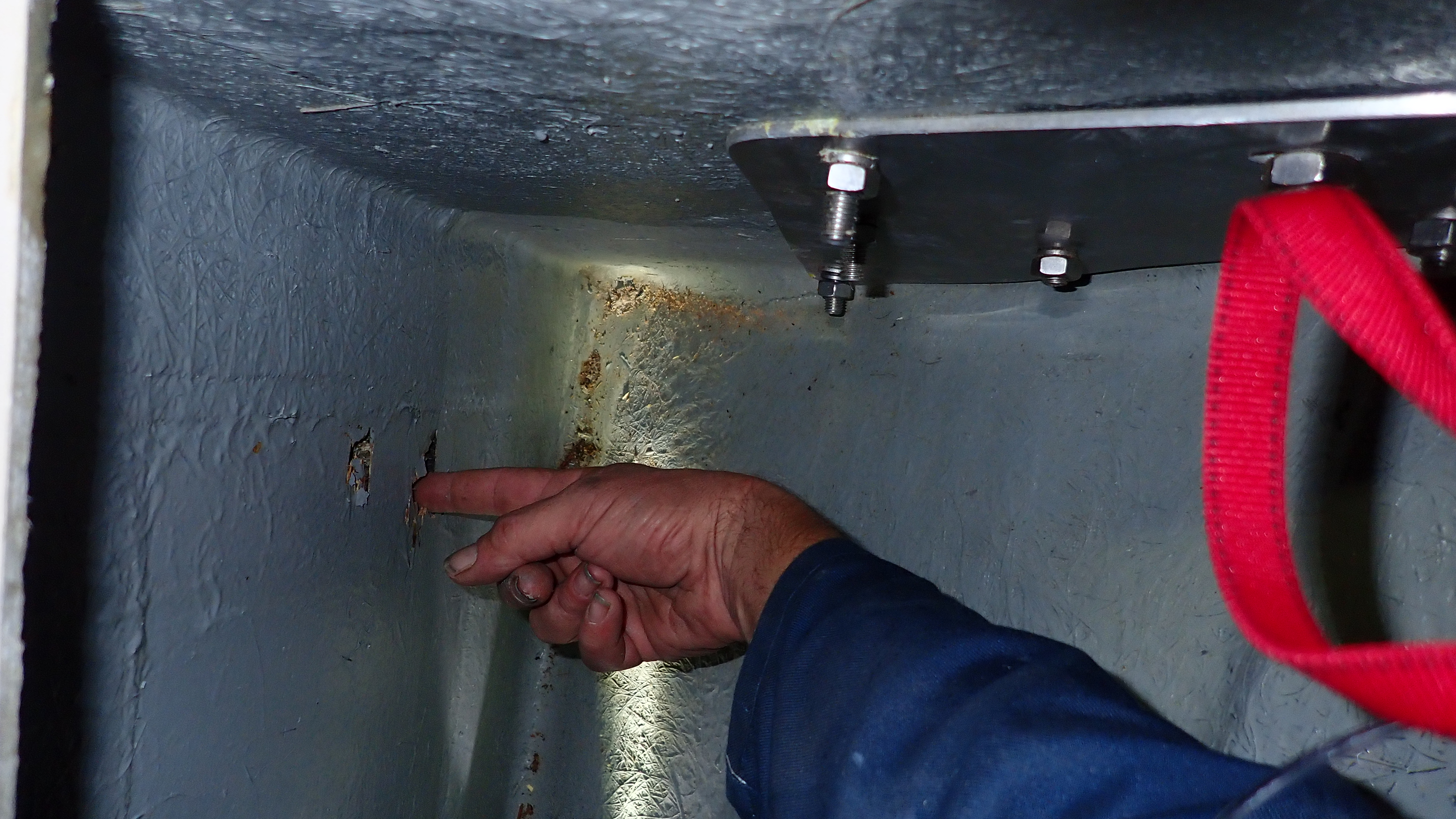
Initially I cut away small sections of the sheathing to investigate.

Looking aft, it was clear that the water tank would need to be removed to get to the other side of this bulkhead.

These areas cut away quickly became bigger as I tried to track the extent of the problem.

Working in small spaces at impossible angles makes you really appreciate a good Multitool.

Whilst not as sodden as the rest, the plywood in the knee was still crumbling to the touch.

This was the very first photo I took for the owner and the focus was at this stage the soft area next to my finger.
Looking at it again later I noticed the tell tail angle of the chainplate bolts and the fact that one of the bolts had almost wound itself out.
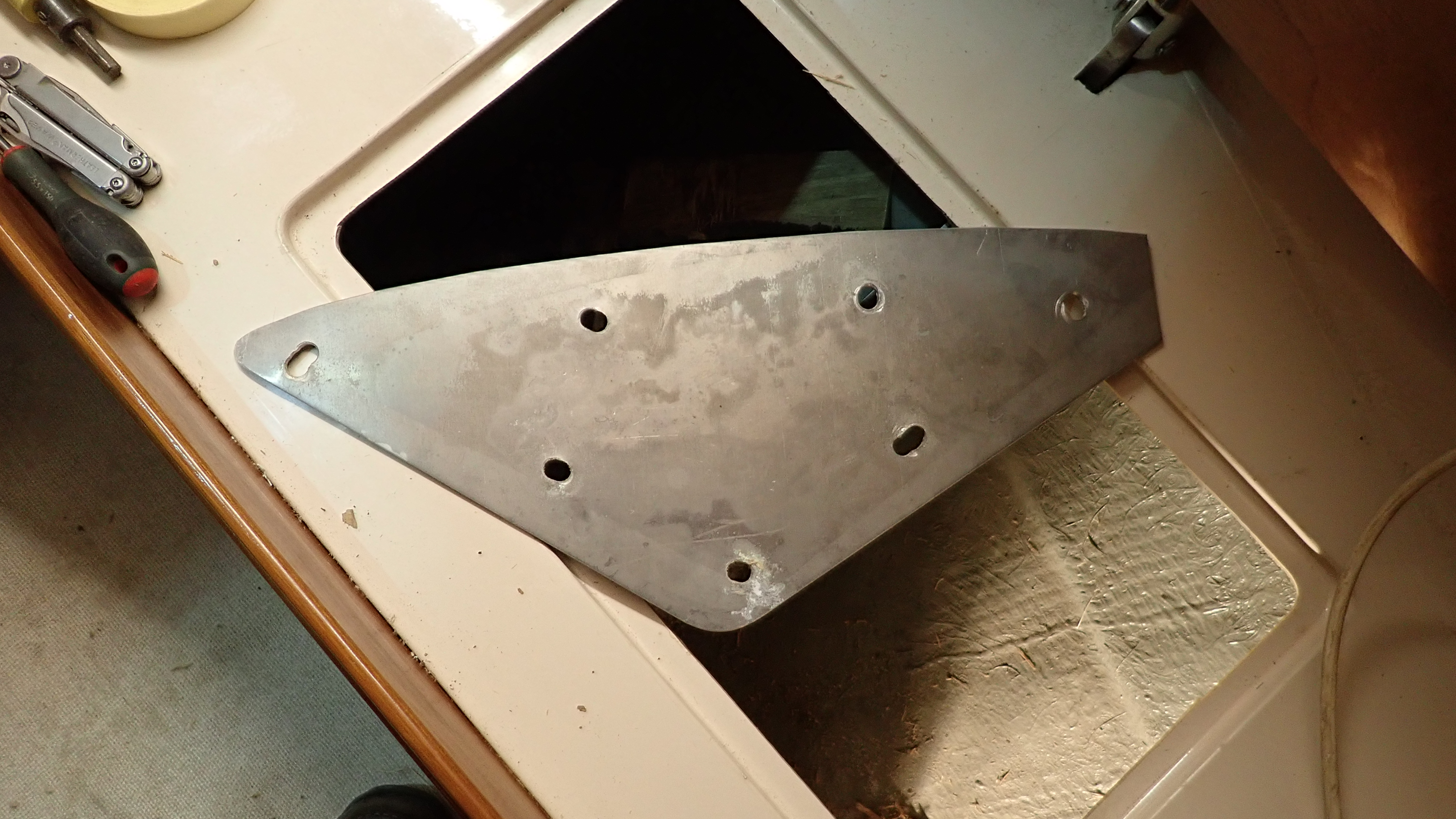
With the backing plate removed it was clear to see how much the chain plate bolts had shifted.
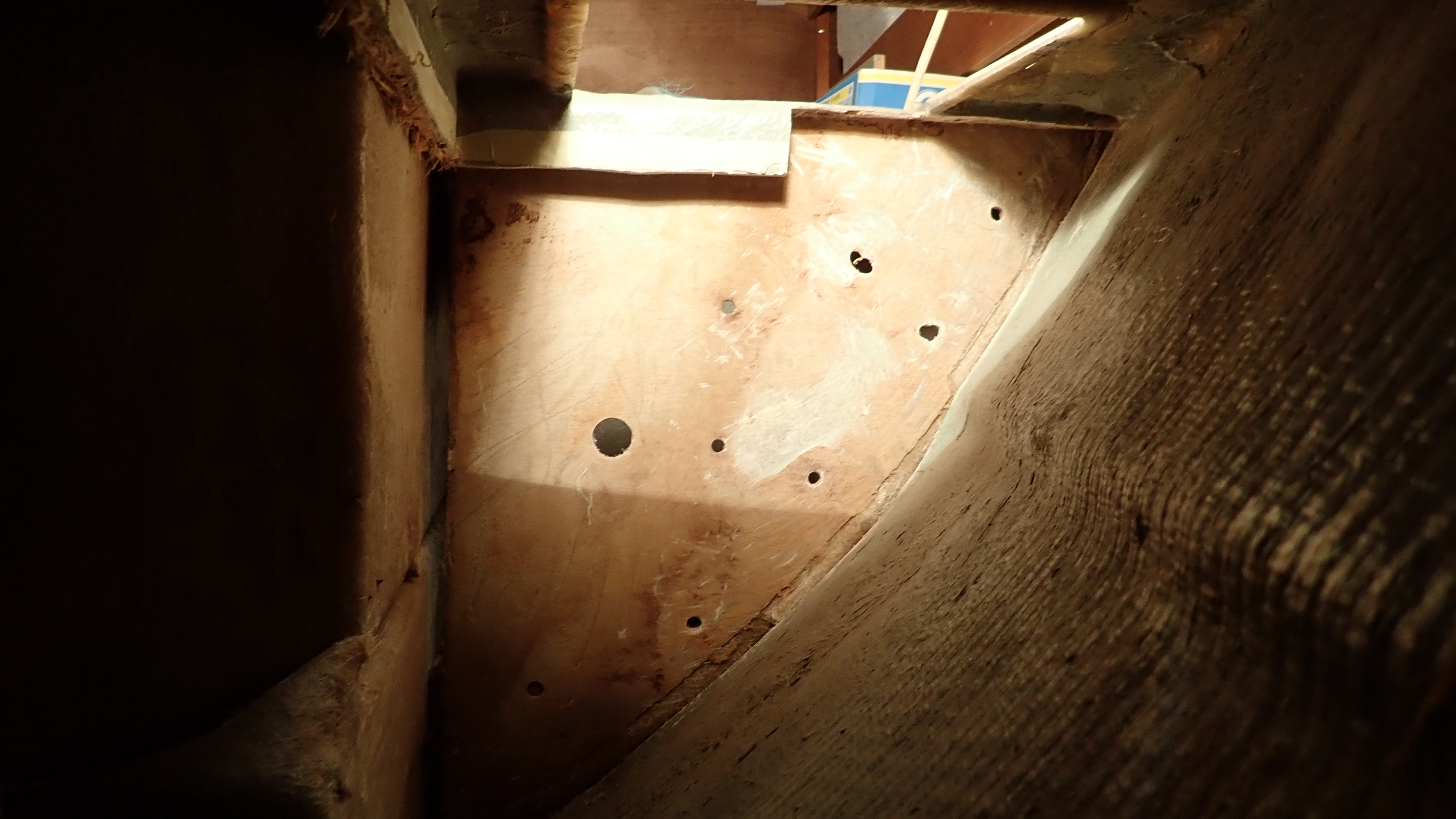
It didn’t take long to clean all the dead wood away leaving one side of the sheathing intact.

We had established that the rot had not effected the main forward lateral bulkhead though given a few more months then this could have been an issue as well.
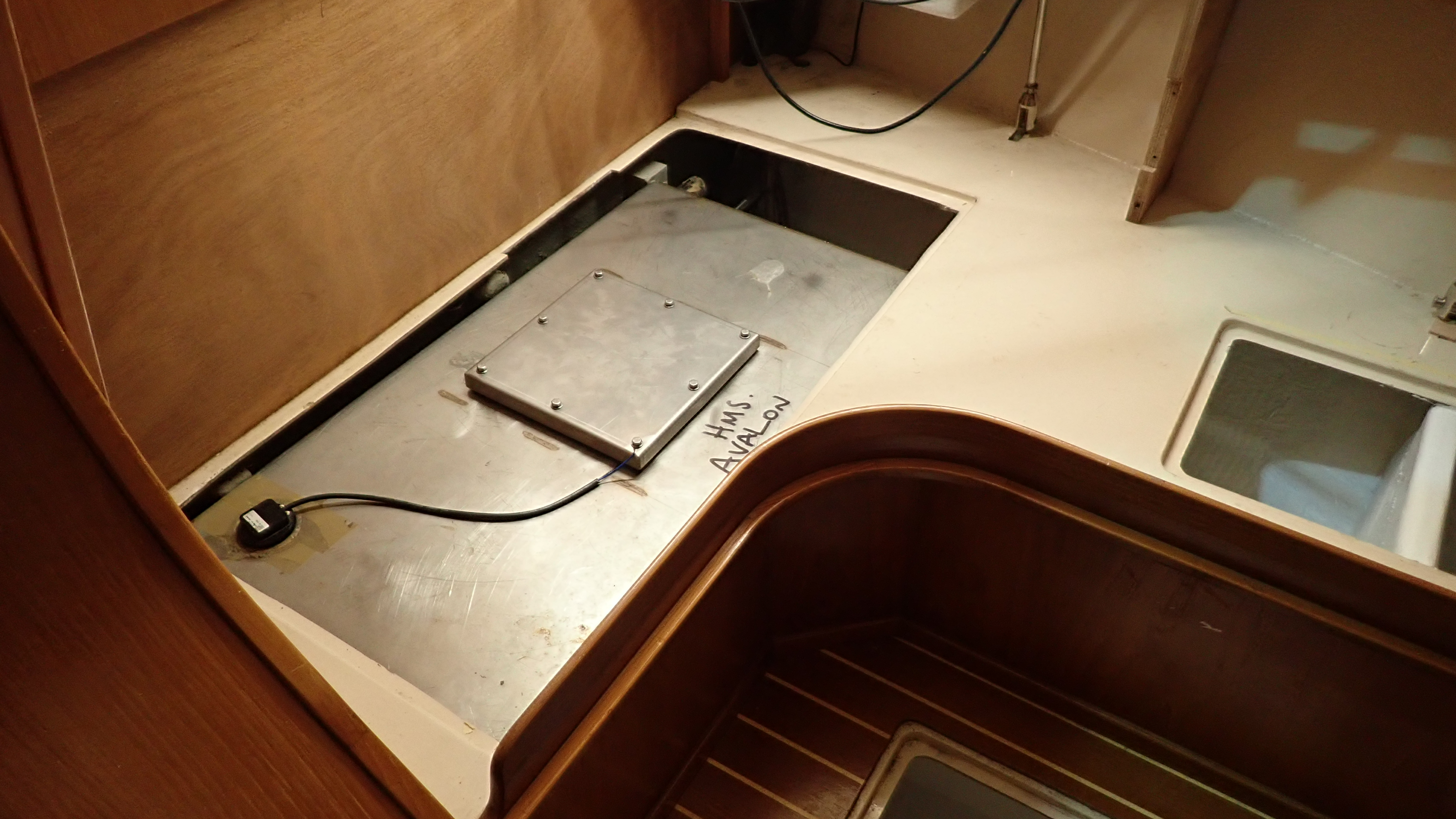
To inspect further aft we needed to remove the stainless water tank.
In this Southerly this was no mean feat as access to the outlet from the tank is extremely difficult.
How the builder thought is was a good idea to place the outlet on the aft side of the tank, under the galley, is beyond me, especially as the factory fitted calorifier, fridge compressor and associated pipework would all have to be removed to gain any kind of reasonable access to the single jubilee clip securing the outlet water pipe.
In the end after three hours of knuckle grazing effort we managed to get a modified spanner on the tank fitting and with an 1/8 of a turn at a time wound the whole fitting out of the tank.
Removal of the tank was then pretty straight forward although we did notice there was no inspection hatch or obvious way to clean the tank.
So we decided to get the tank modified, blanking the original outlet and fitting a new one on the forward side which would have much easier access and also to fit an inspection hatch.
With the tank removed we could continue the rot chase and with relief it was found not to have continued into any of the galley supporting structure and bulkheads.
The aft chainplate knee however was found to be rotten and had twisted its position almost as much as the main chainplate knee and the water tank locker side would have to be replaced.

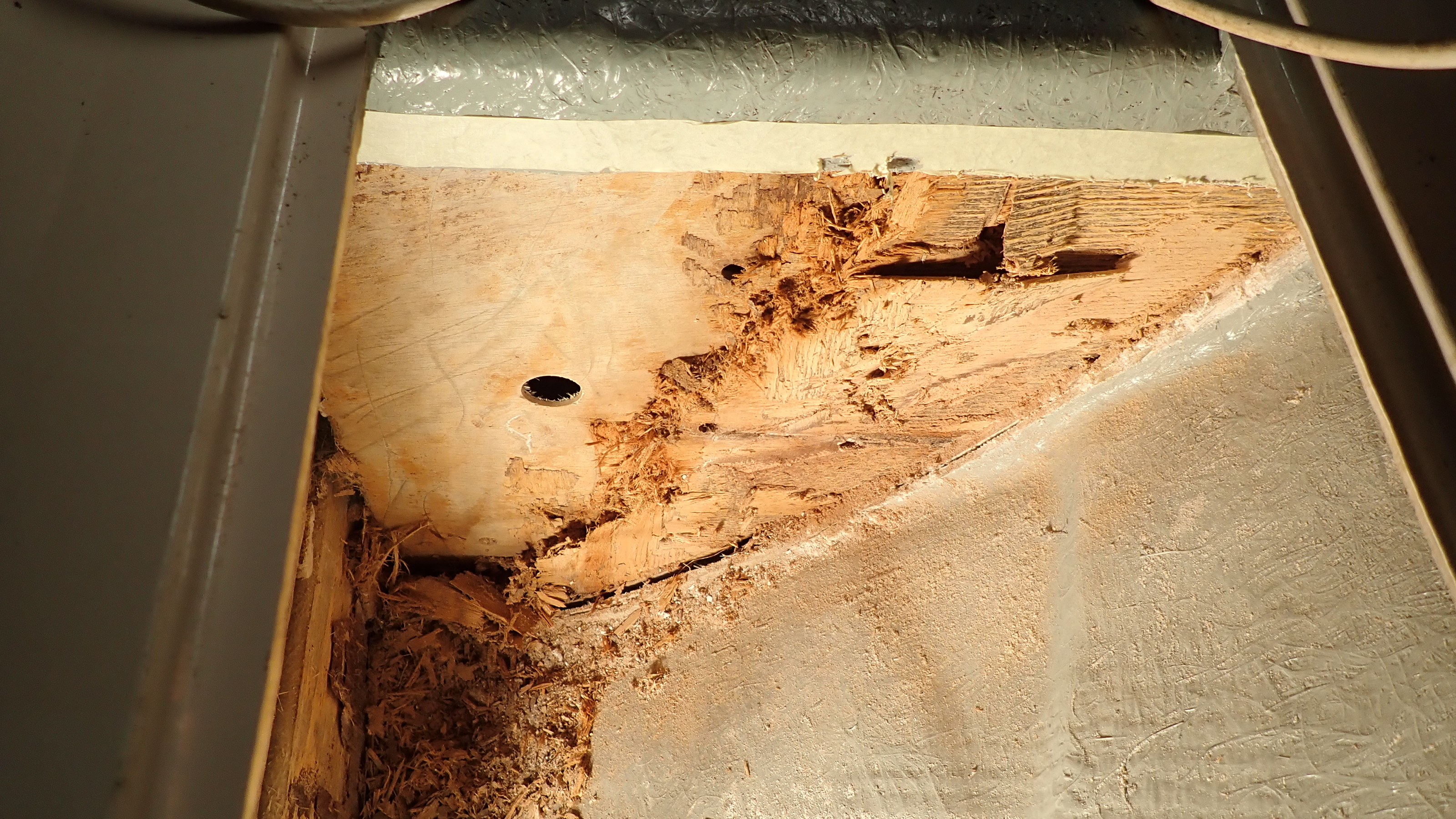
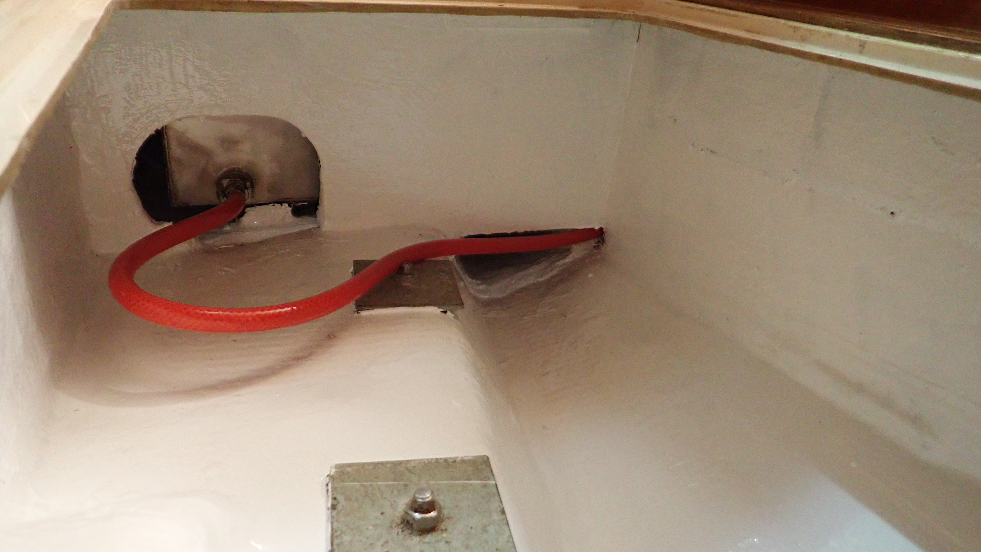
Access to the outlet of the water tank was almost impossible to get too.

The outlet pipe runs through the hole next to the lower tank support.

The aft chainplate knee was found to be in as poor condition as the rest, though this flaked away in papery sheets.

It was by now obvious that over time,  the connected sheathed plywood sections had rotted due to moisture getting sucked in by capillary action.
However even though we strongly suspected the bottom inside corner of the forward locker to be the initial entry point I couldn’t find any definitive proof.
With this in mind I wasn’t keen to simply replace the wood for the fear of the same problem recurring in future.
Given the excellent condition of the rest of the interior I also needed a solution that didn’t require disassembly of the entire saloon seating area.
So I decided to replace all the panels except for the knees, using a 10mm thick plastic honeycomb core, called Nidaplast, which would then have two layers of 250 gram chopped strand matt laminated to each side.
The resulting panel is stiffer and lighter than plywood , with the obvious additional benefit of there being nothing to rot in the future.
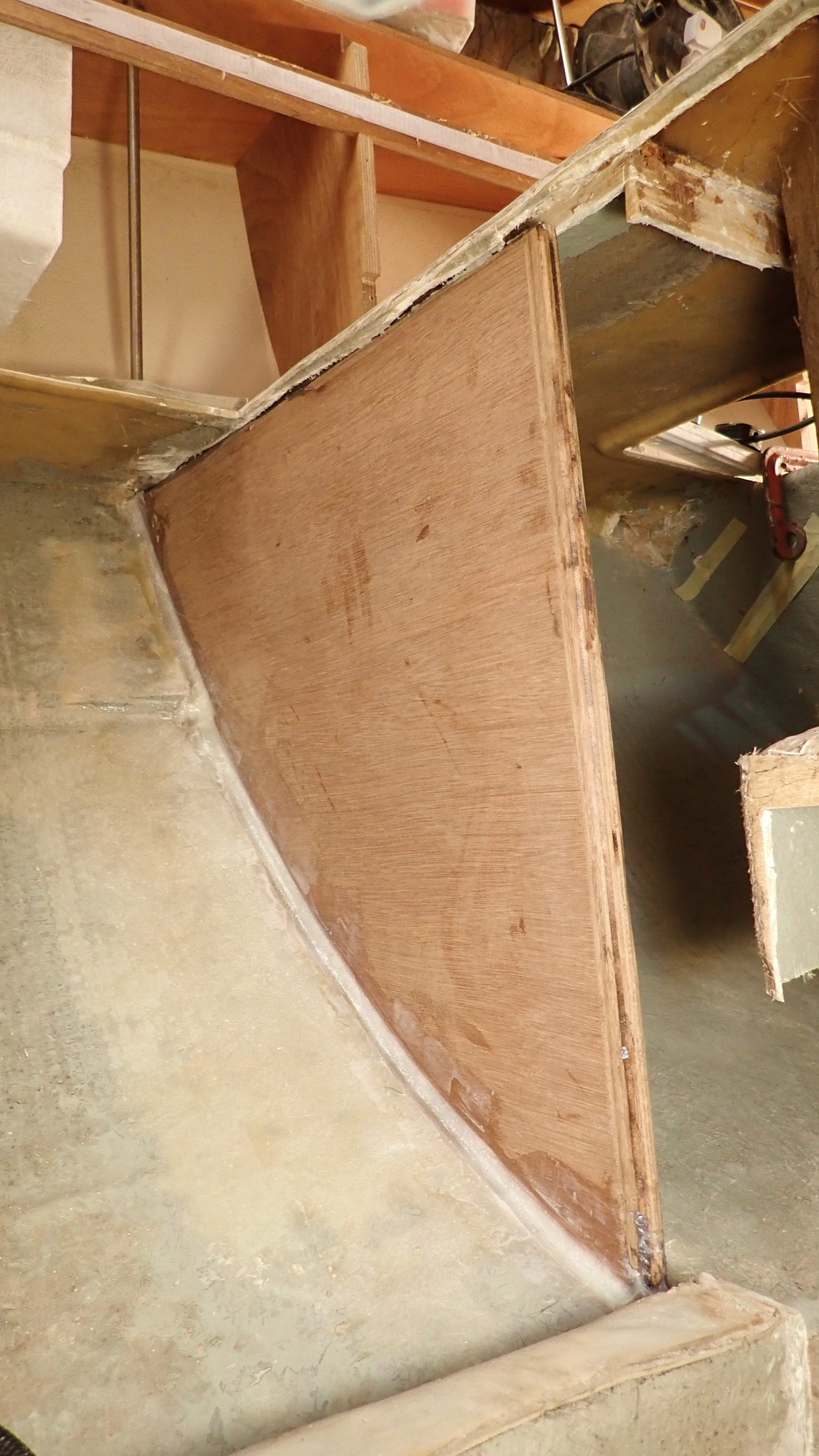
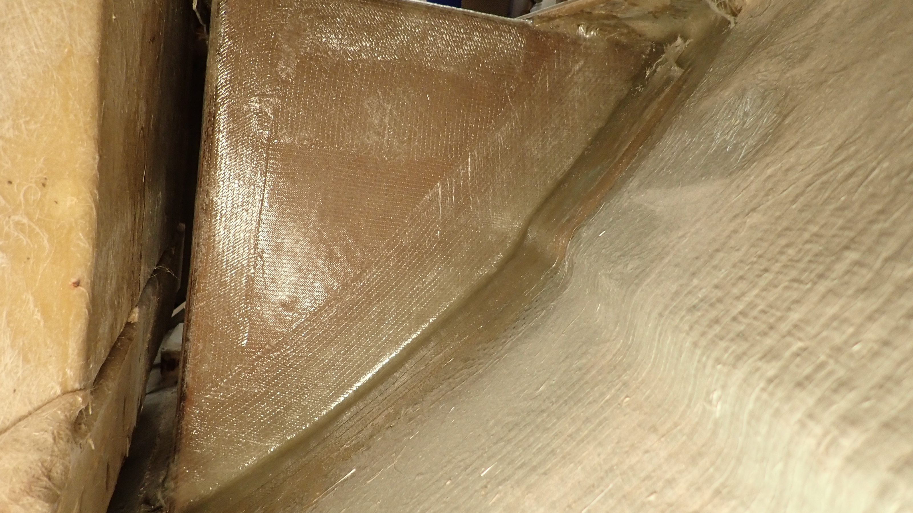
The chainplate knees however would be 25mm marine plywood, due to the compression of the chain plate bolts. The knees would be glassed to the hull and sheaved individually.

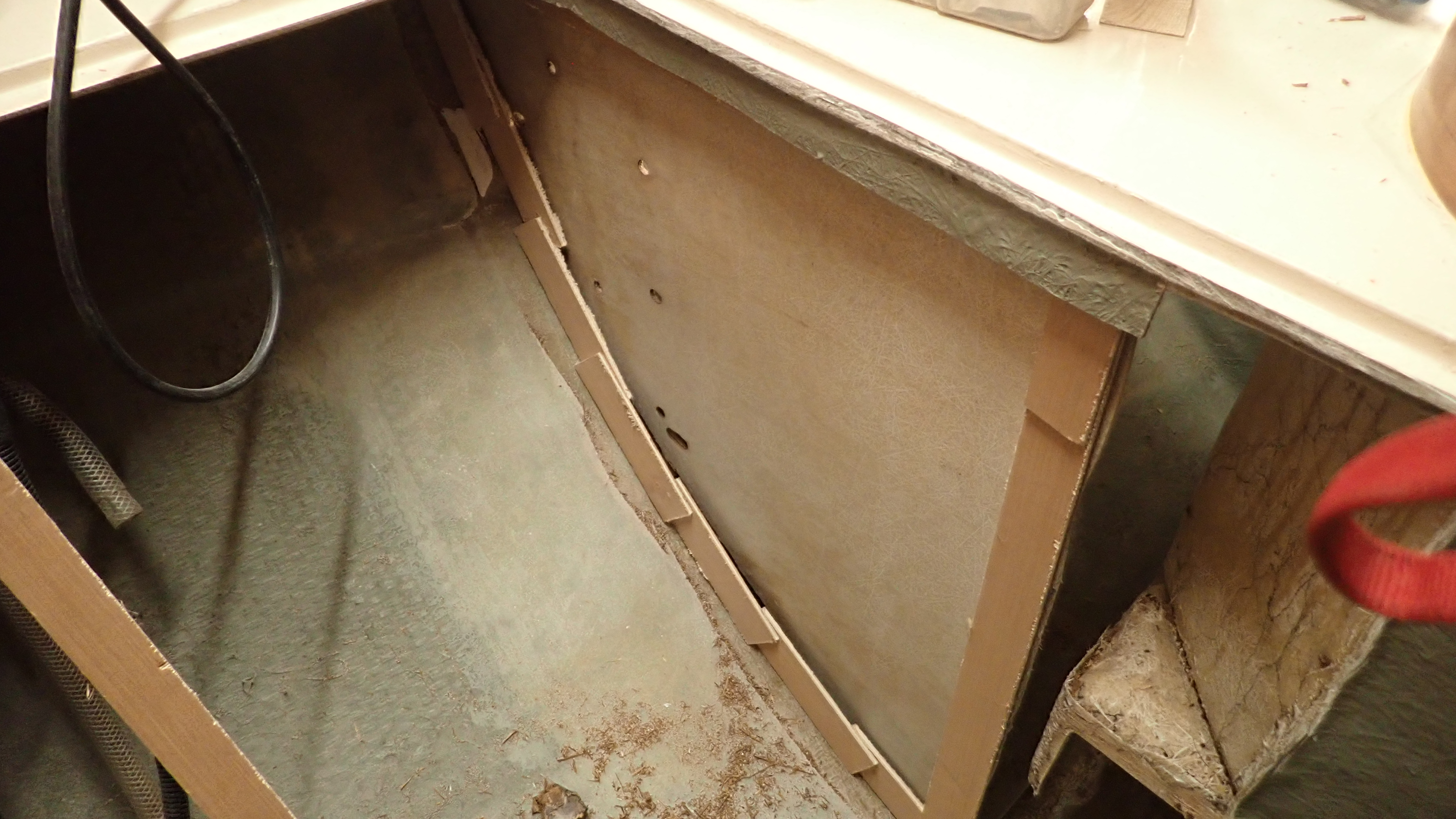
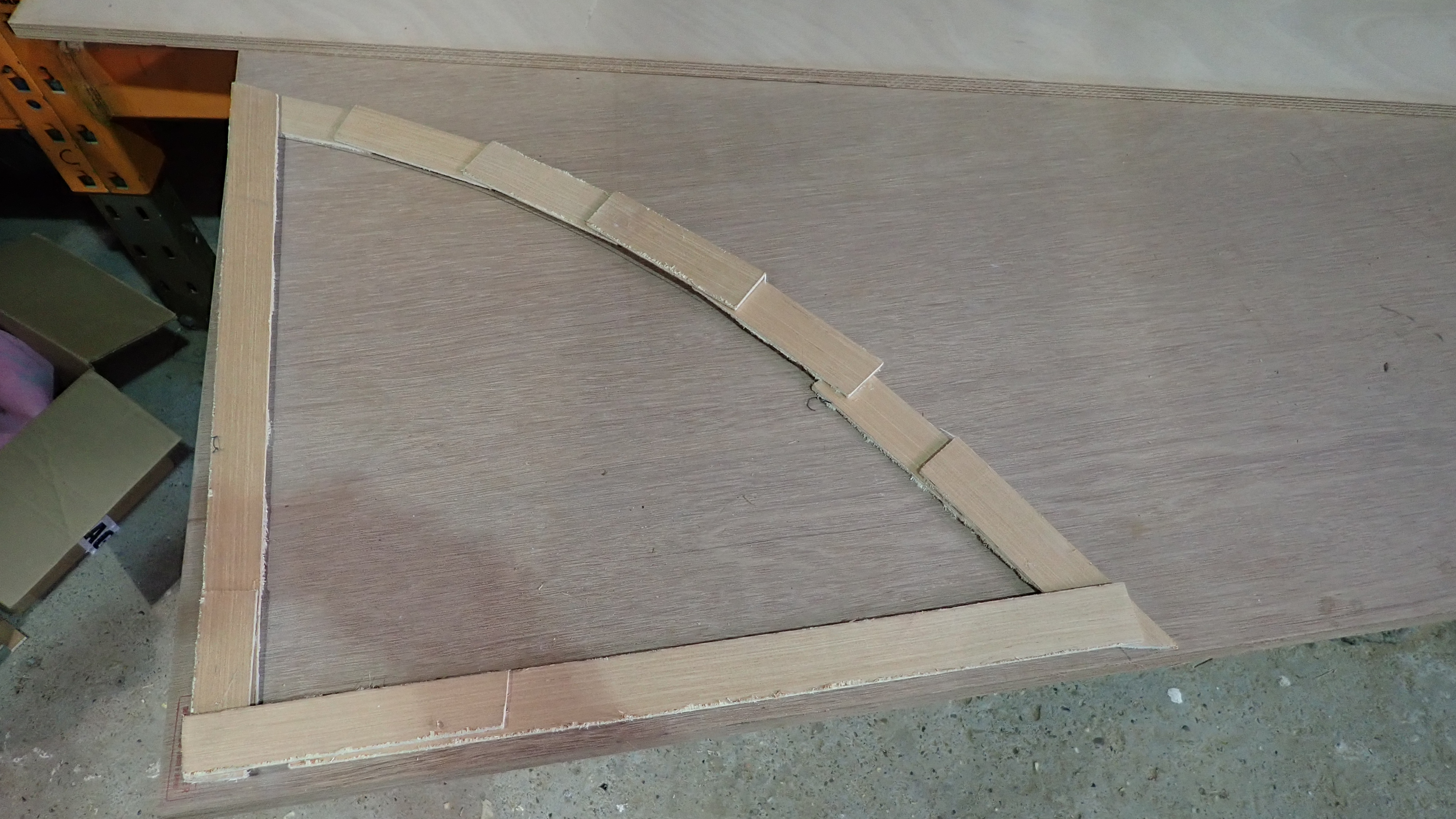
I find the easiest way to template an awkward shape is to use 2″ wide strips of hardboard and stick them together using a hot glue gun.
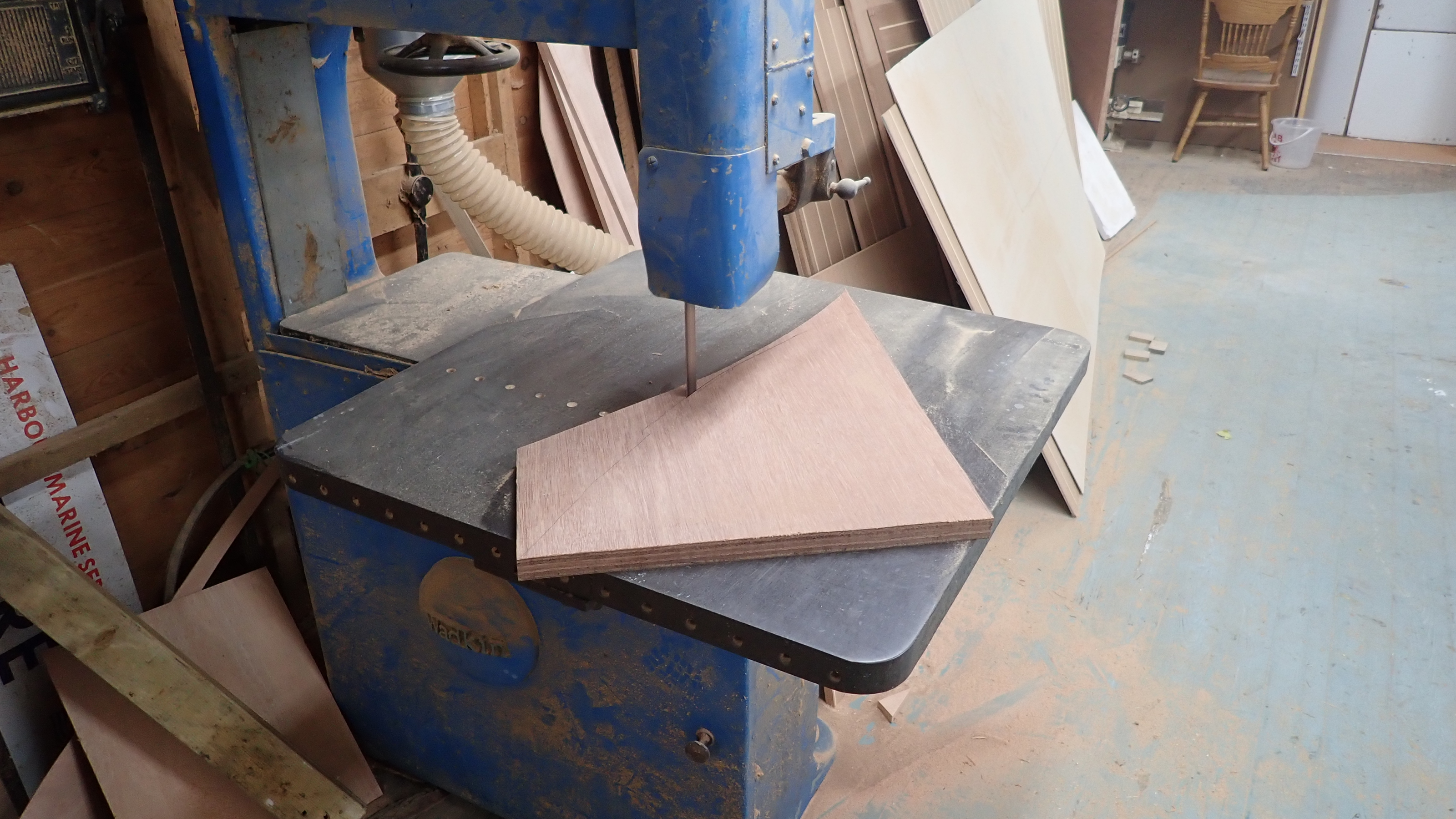
The resulting shape can then be transferred over to the sheet material you wish to use, marked up and cut out.

1, Hardboard strips are glued around the perimeter to create a template.

2, The template can then be used to mark up a new panel.

3, Using a jigsaw or bandsaw the new panel is cut out.

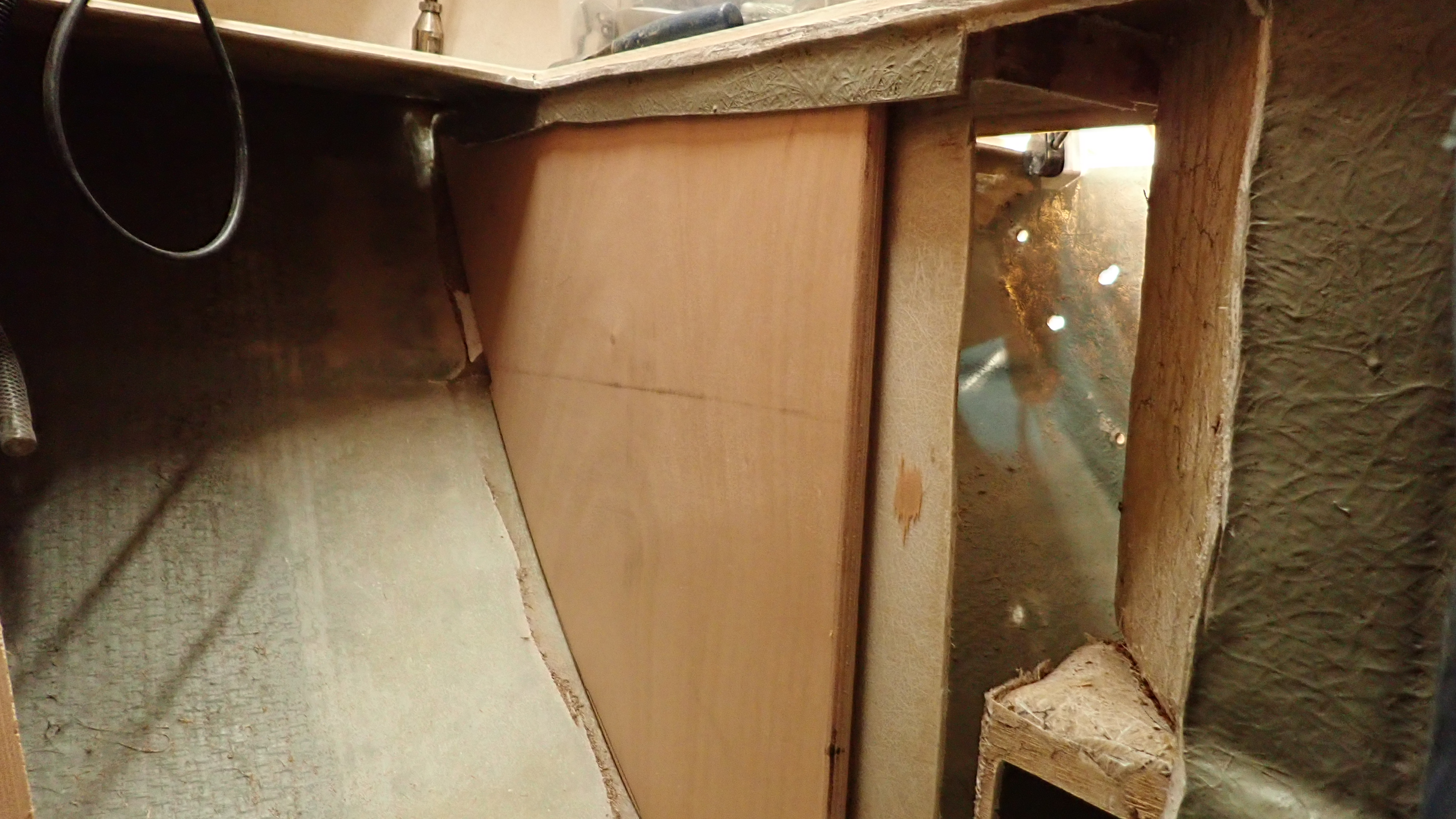
3, Dry fit the panel to check the fit.

When I removed the old rotten wood I removed one side of the sheathing only.
The remaining sheathing side was cleaned and keyed so that it would provide a solid location for the new knee.
The new plywood was given a coat of neat west epoxy and then a thickened mix using 406 colloidal silica was liberally applied to the side of the old sheathing.
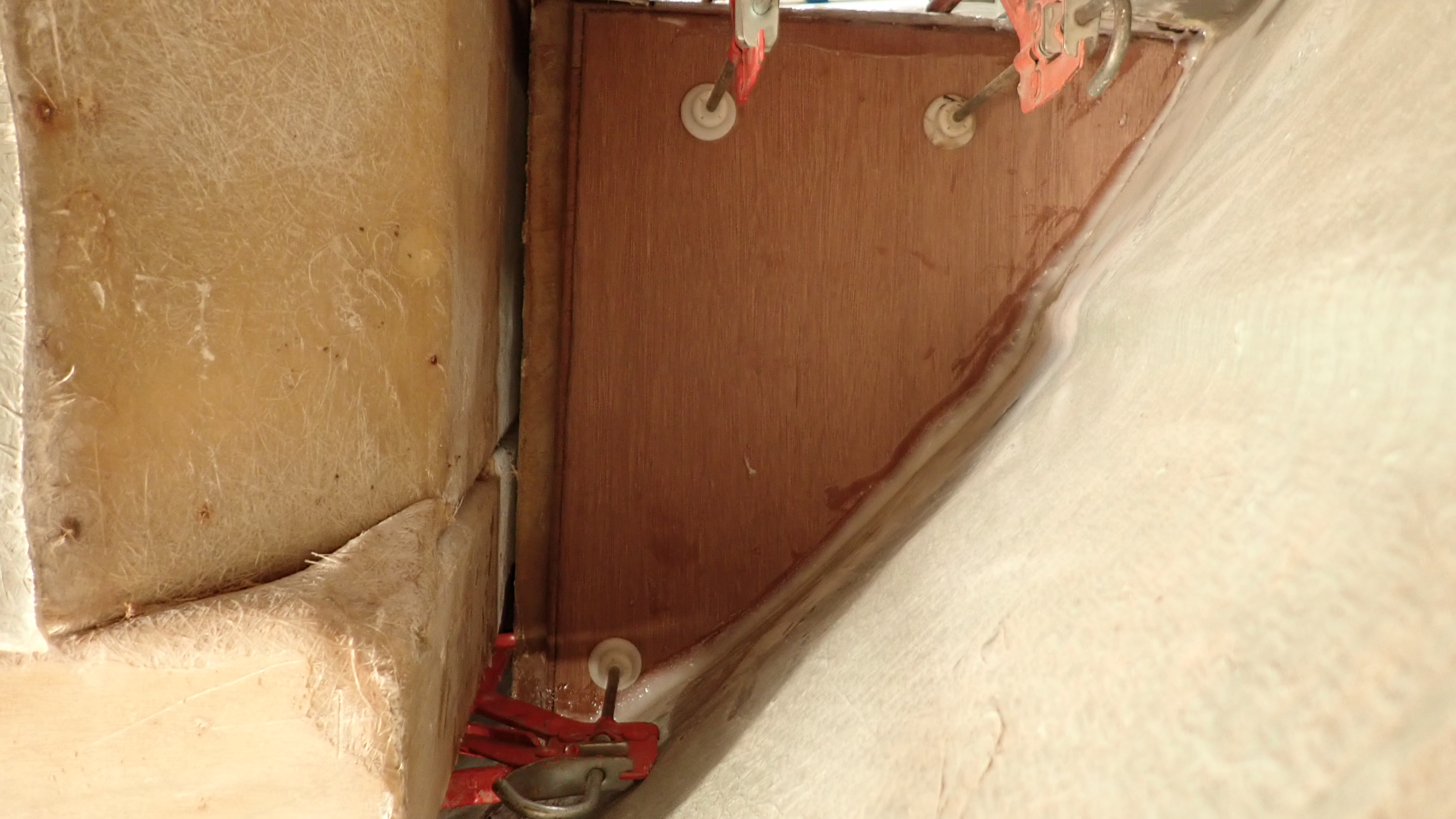
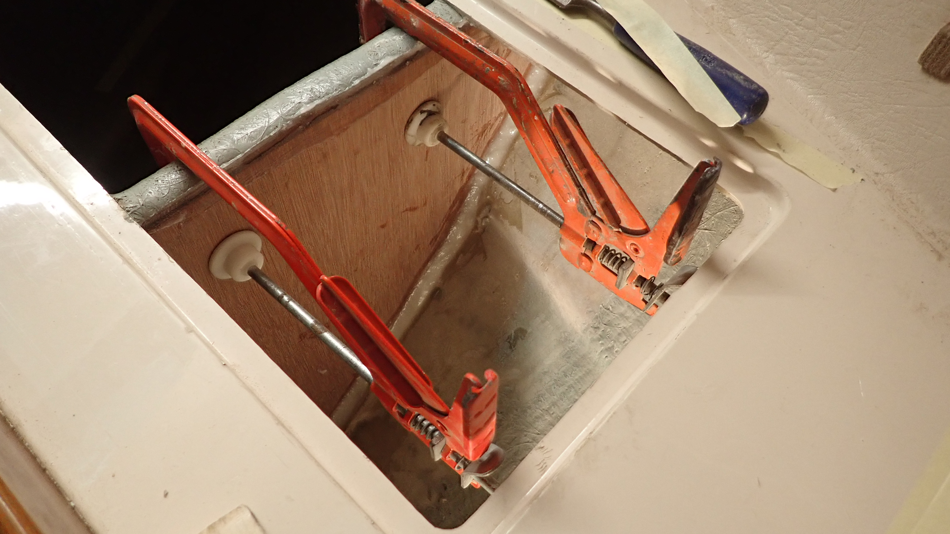
The new panel was inserted and clamped into position.
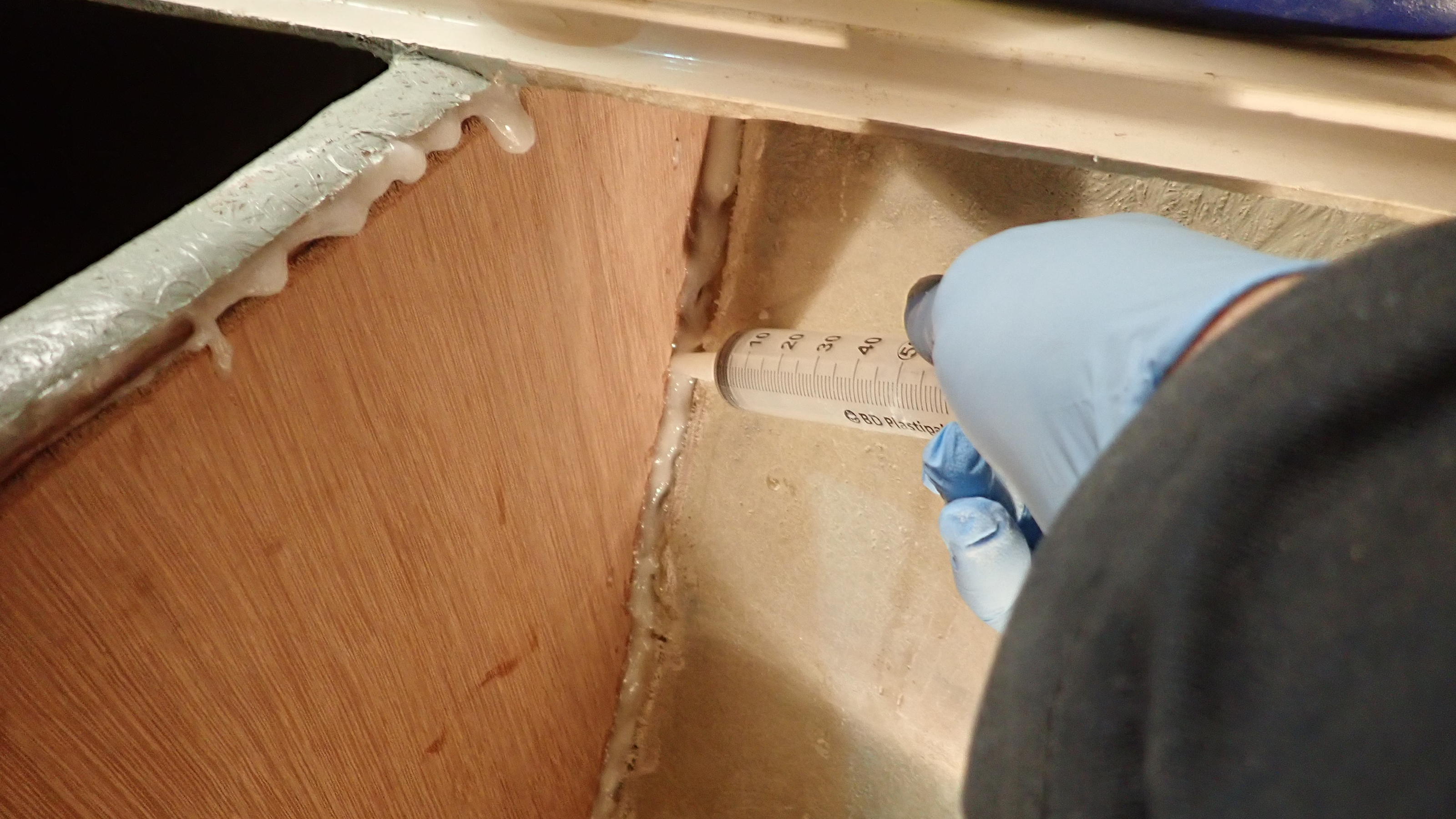
Using a large syringe more epoxy/406 mix was injected into the joints between the knee and the hull.
Then using a tongue depressor an epoxy fillet was created round the edges.

1, We use a large syringe to inject epoxy/406 mix into difficult places.

2, Once in position the panel can be clamped in place.

3, A fillet of epoxy is created round joint.

24 hours later the epoxy has set and the clamps can be removed.
The surrounding area can then be cleaned, removing al traces of stray epoxy apart from the fillet and the hull was vigorously keyed using a grinder with a flap disc ready for the knee to be laminated to the hull and then sheathed.
Grinding and sanding old grp is a horrible, messy process, generating a huge amount of fine dust that gets everywhere.
Using a sander with dust extraction is another method but it takes at least three times as long, so I take some time and sheet off the local area, don disposable overalls, mask and goggles, take a deep breath and get stuck in.
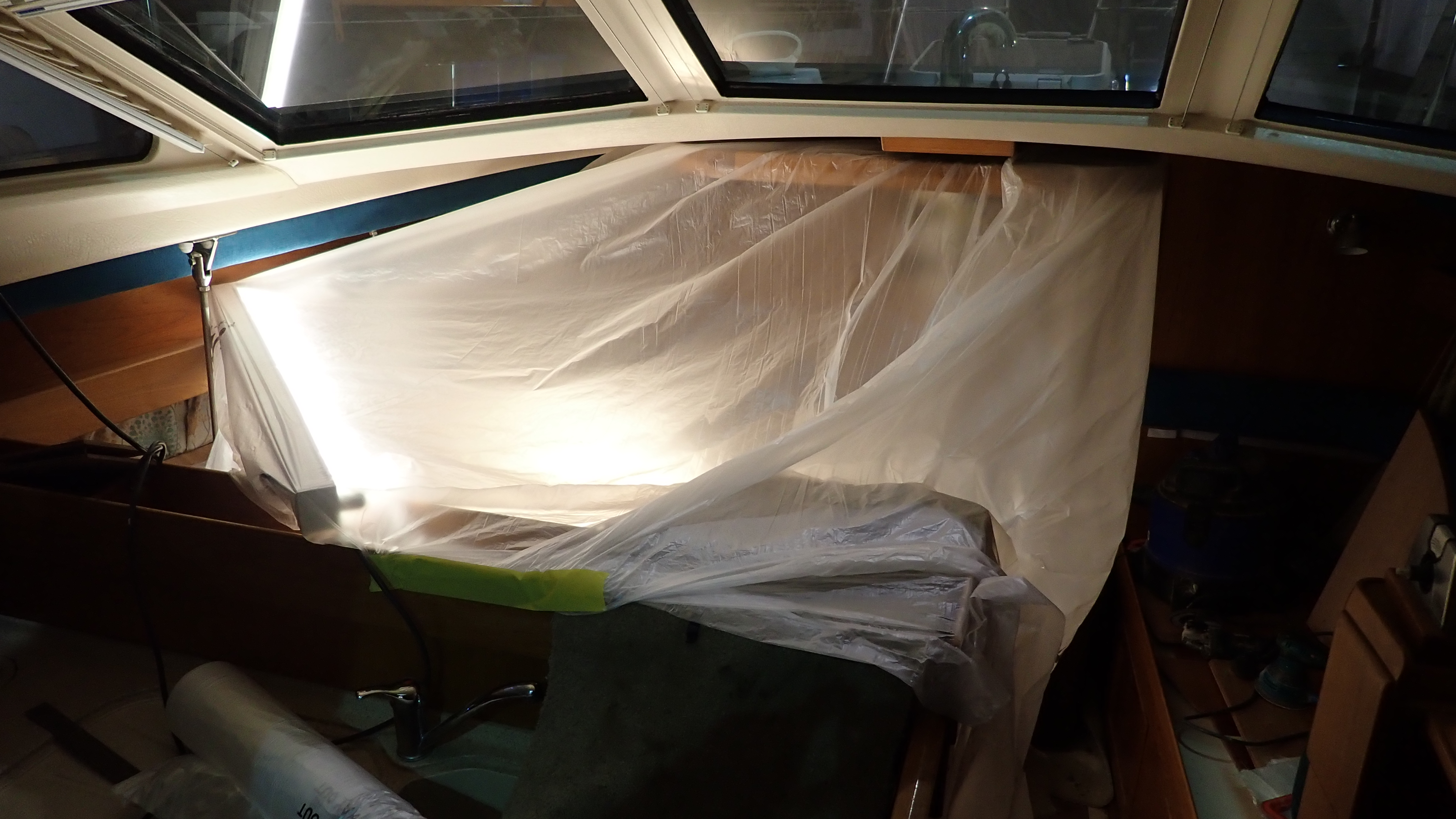
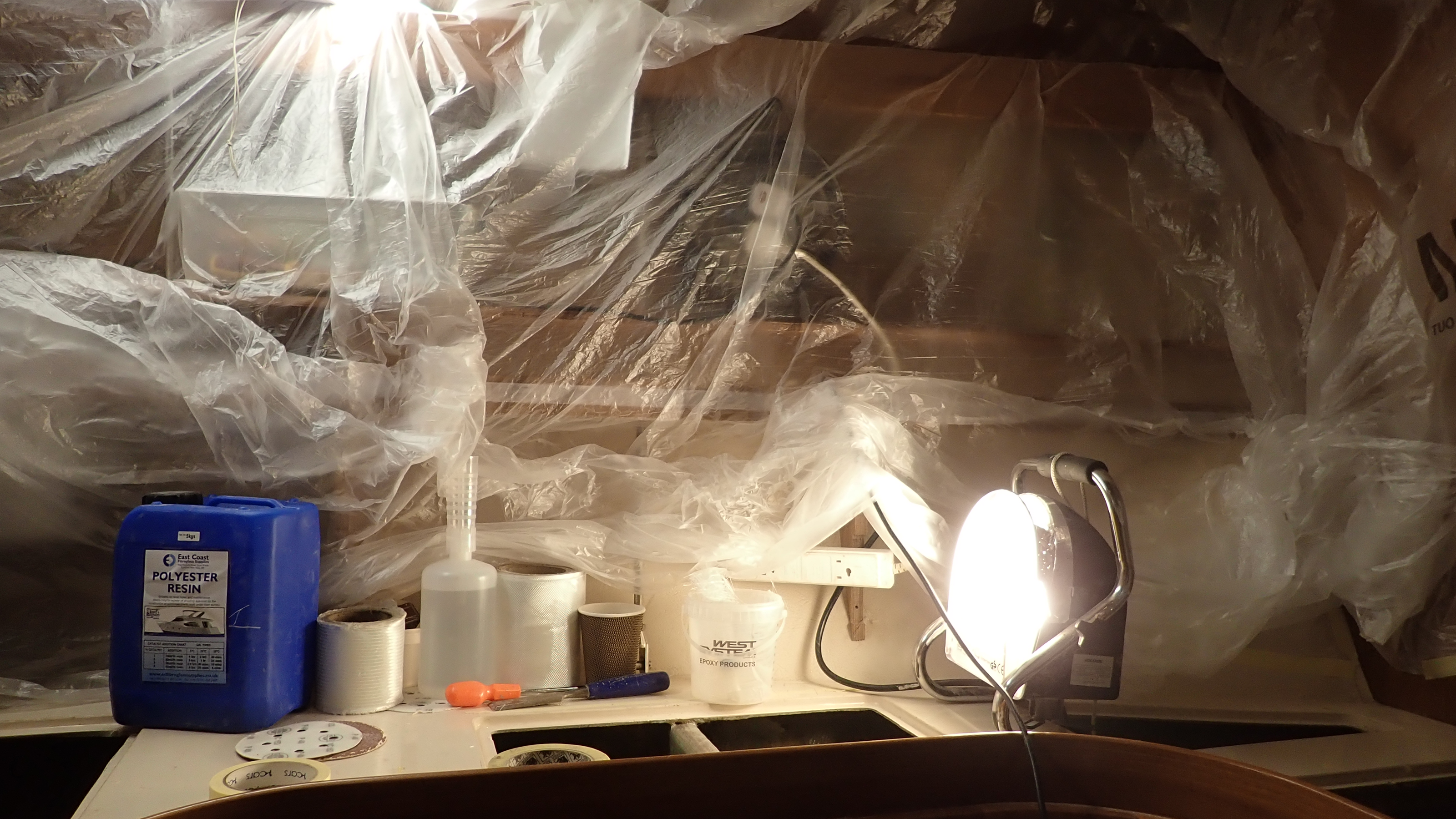
When grinding the hull the area needs to be sheeted off to prevent dust getting everywhere
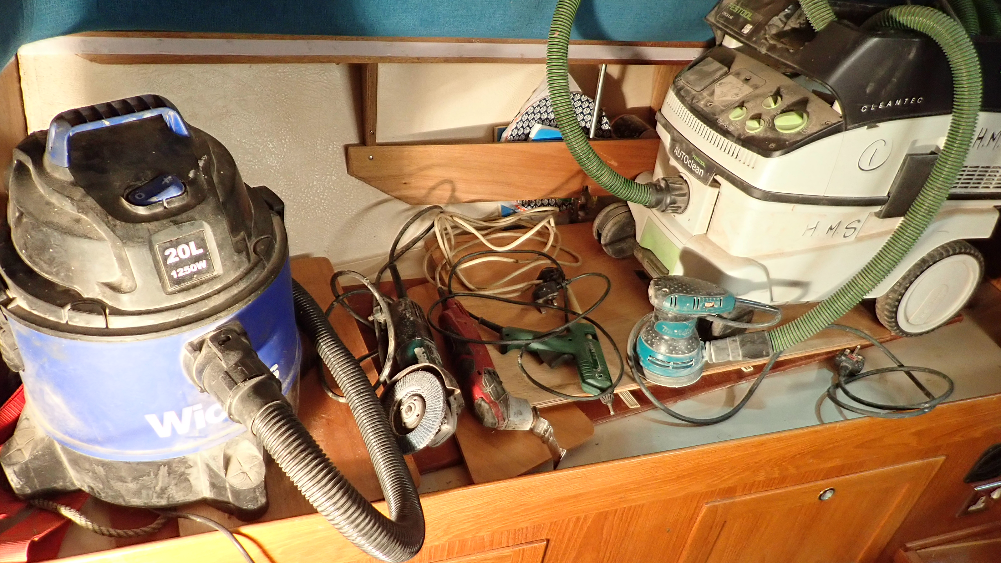
The main tools used thus far are the vacuum, 4″ grinder with 40grit flap wheel, multitool with grp gutting blade, hot glue gun, small da sander with dust extraction. oh and lots of lights, preferably florescent or led rather than heat generating halogen spots.

After 20 minutes of grinding the hull is keyed and the knee is ready for laminating.

Once the dust generating process has finished the sheeting can be removed and everything is given a through vac down to remove all traces of dust.
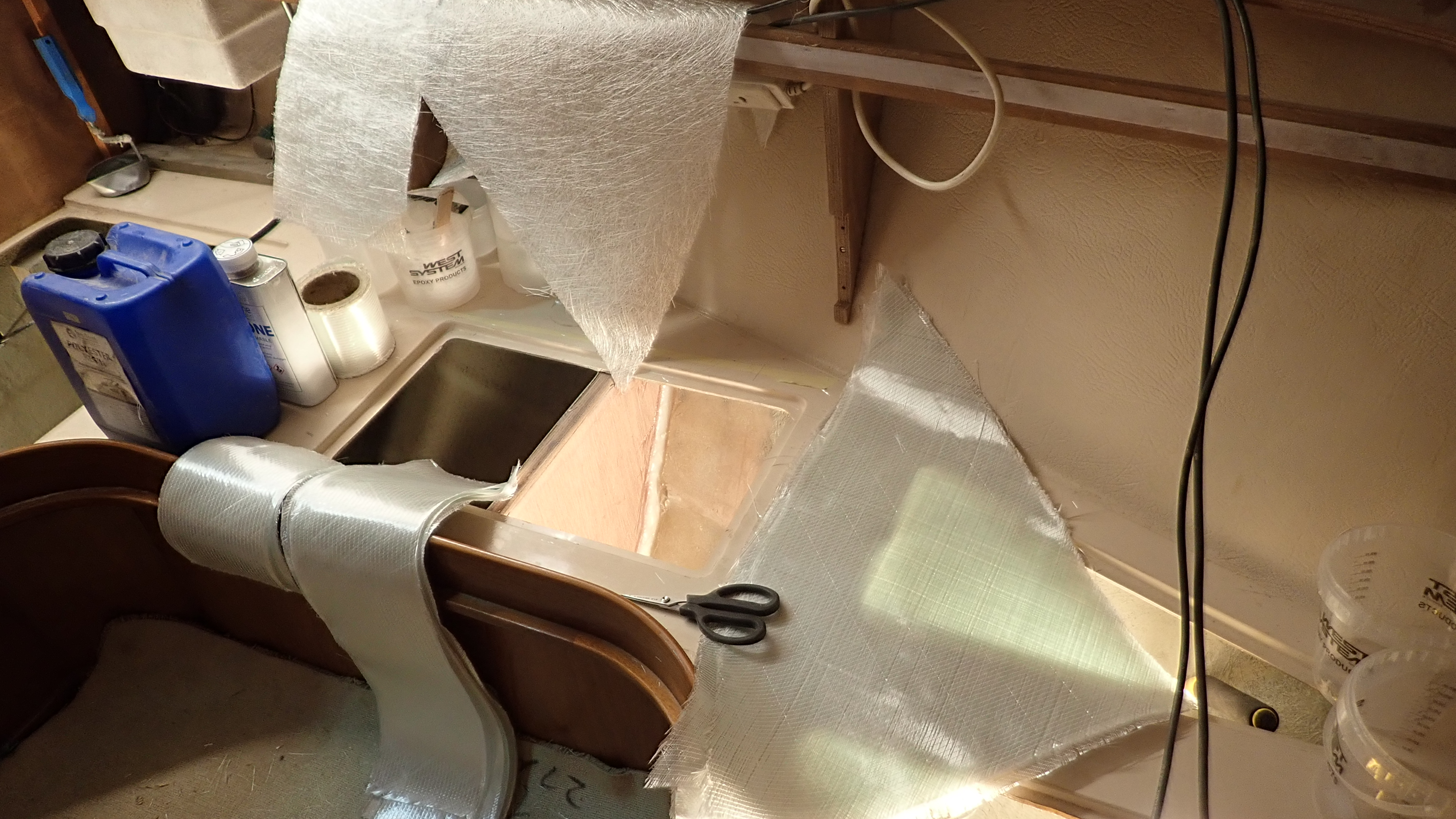
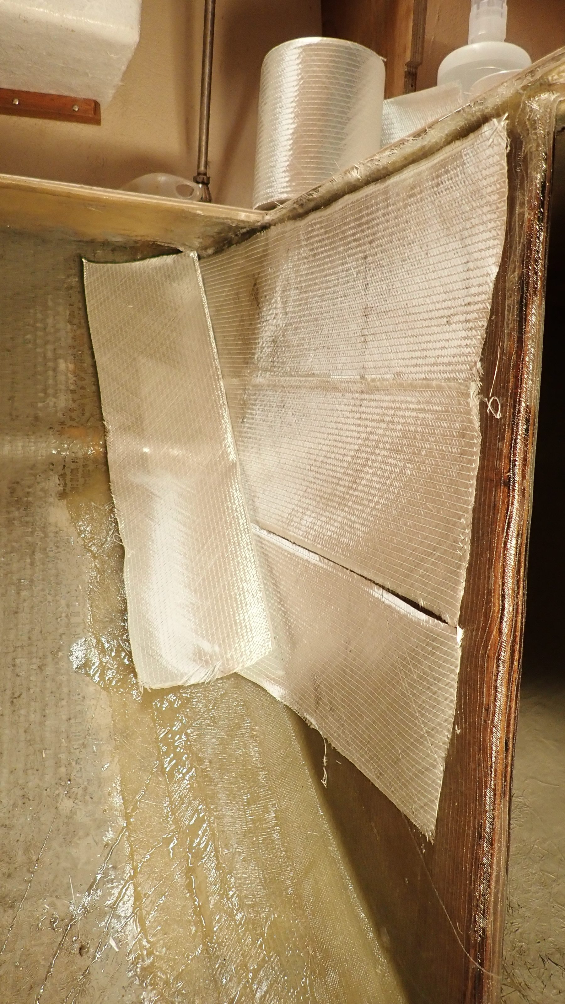
The glass cloth can now be cut out ready for laminating.
Do not be tempted to do this during the laminating process as what can be a messy process at the best of times can quickly turn into a nightmare.
I used a mixture of cloths.
Firstly 250g chopped strand mat.
This in my view provides a better initial key to the hull and bare wood than woven cloth.
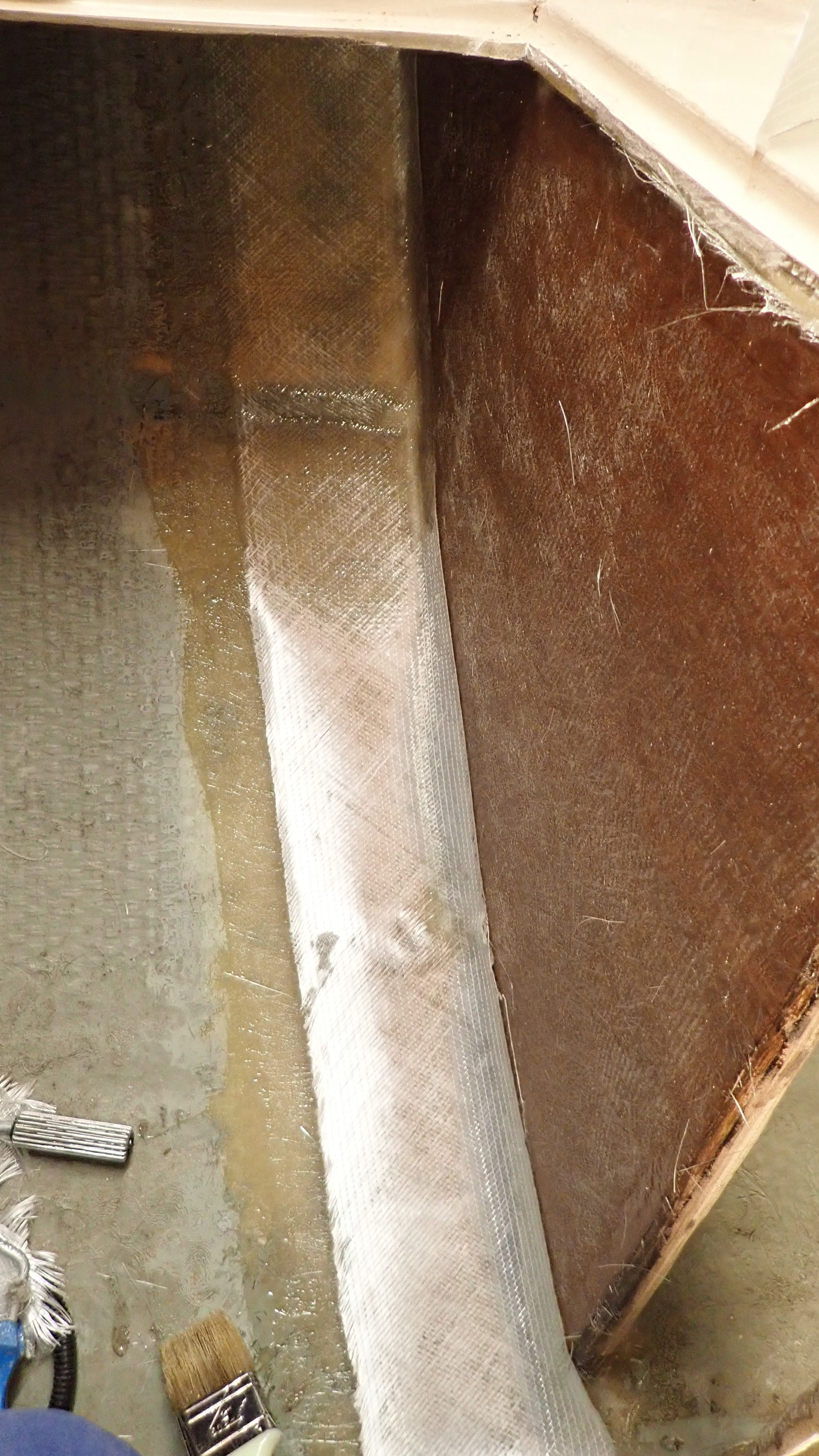
Followed by 300g biaxial woven cloth, which smooths everything out, it falls to shape well and wets out very easily.
The main strength is provided using overlapped layers of 150mm wide 450g biaxial cloth tape.
Whilst this tape is thick and quite heavy it falls into place well and there is usually enough residual resin in the previous layers to wet it out using a roller.

I think I’ve pointed out before in earlier articles that its important not to use too much resin.
Any fool can wet out layers of chopped strand mat by flooding it with resin but this results in a weak, brittle and potentially dangerous layup.
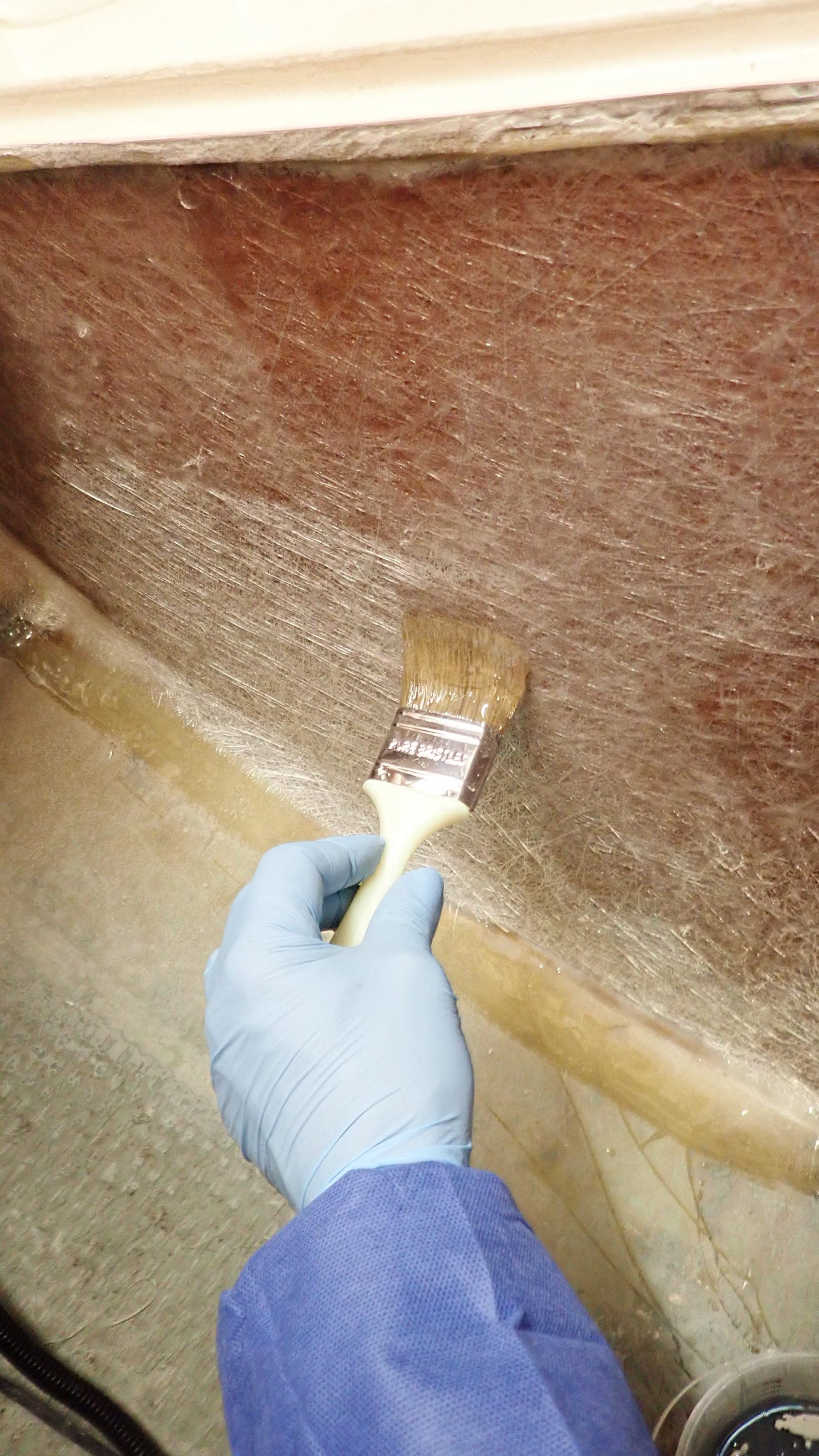
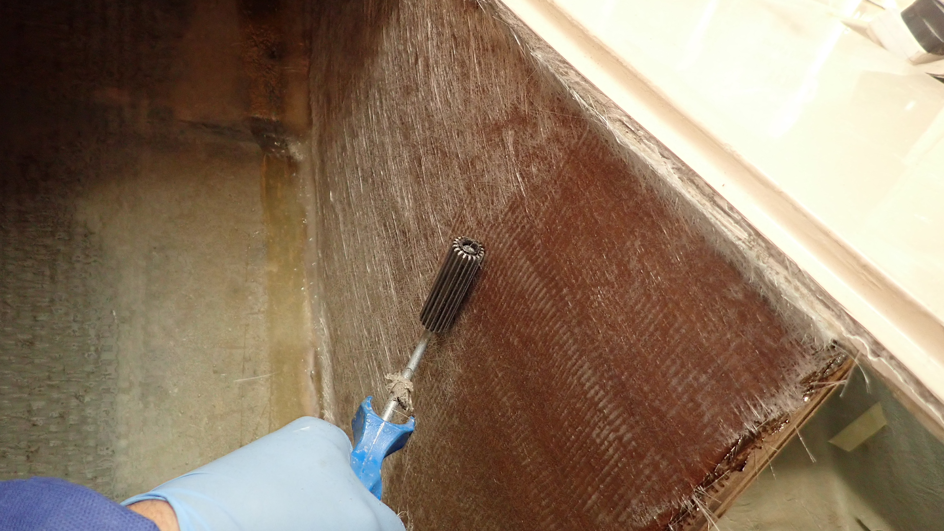
Use the resin sparingly and work it in with the brush and roller.
It takes time and patience done correctly, around a full working day to fully laminate a knee in this case.
If it was any faster then I’d be concerned that the layup was resin rich.

Cutting the panels and organising them in sequenced piles helps you keep track during the laminating process.

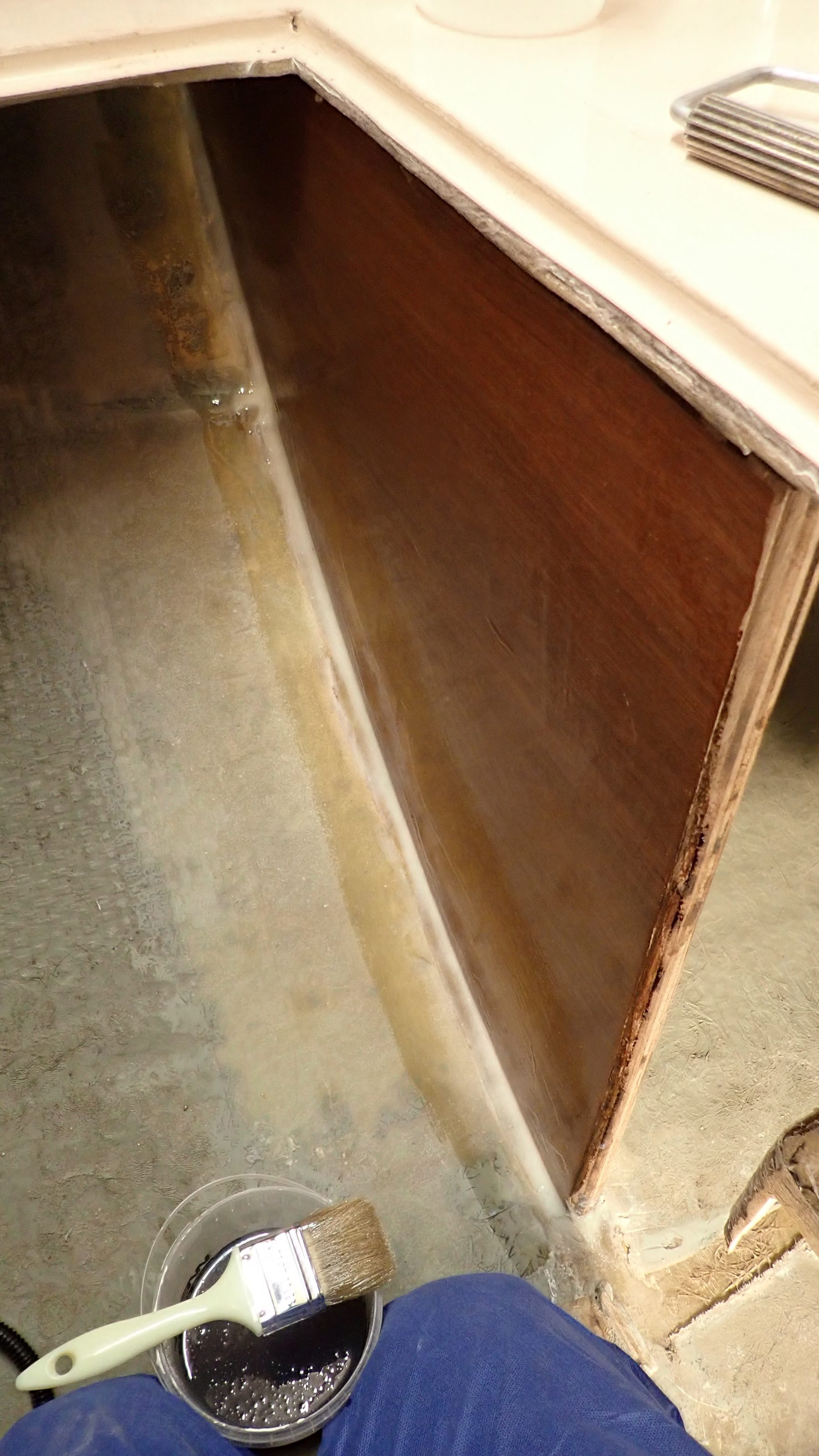
1, Wet out the panel with neat catalyzed resin to avoid getting any dry areas.

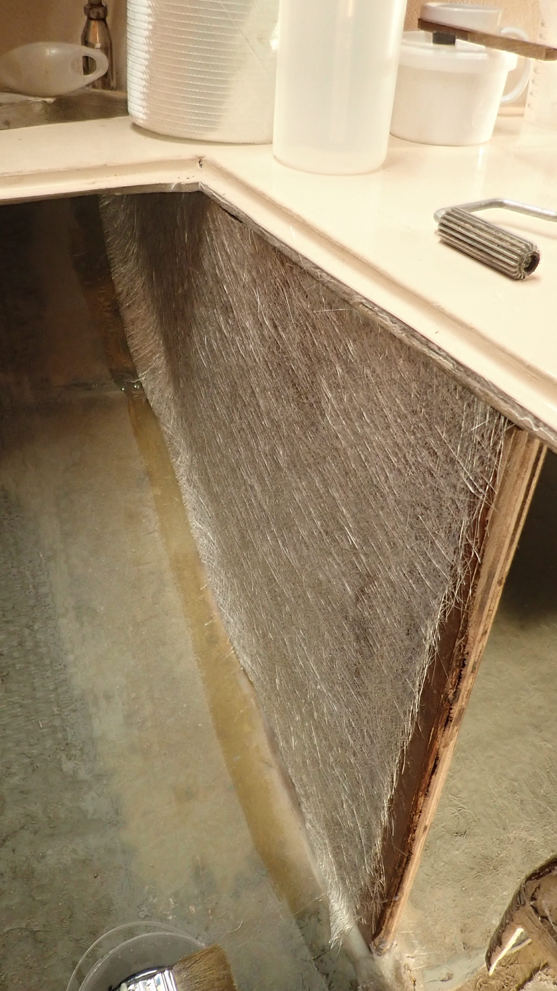
2, Position the first layer of csm on the panel.

3, Using a 2″ brush you can add resin directly to the cloth.

4, Then using a consolidation roller you can wet out the cloth without using too much resin.

5, When the csm layers have been done you can add the overlapped layers of 450g tape.

6, Further layers of 450g tape are added over the csm.
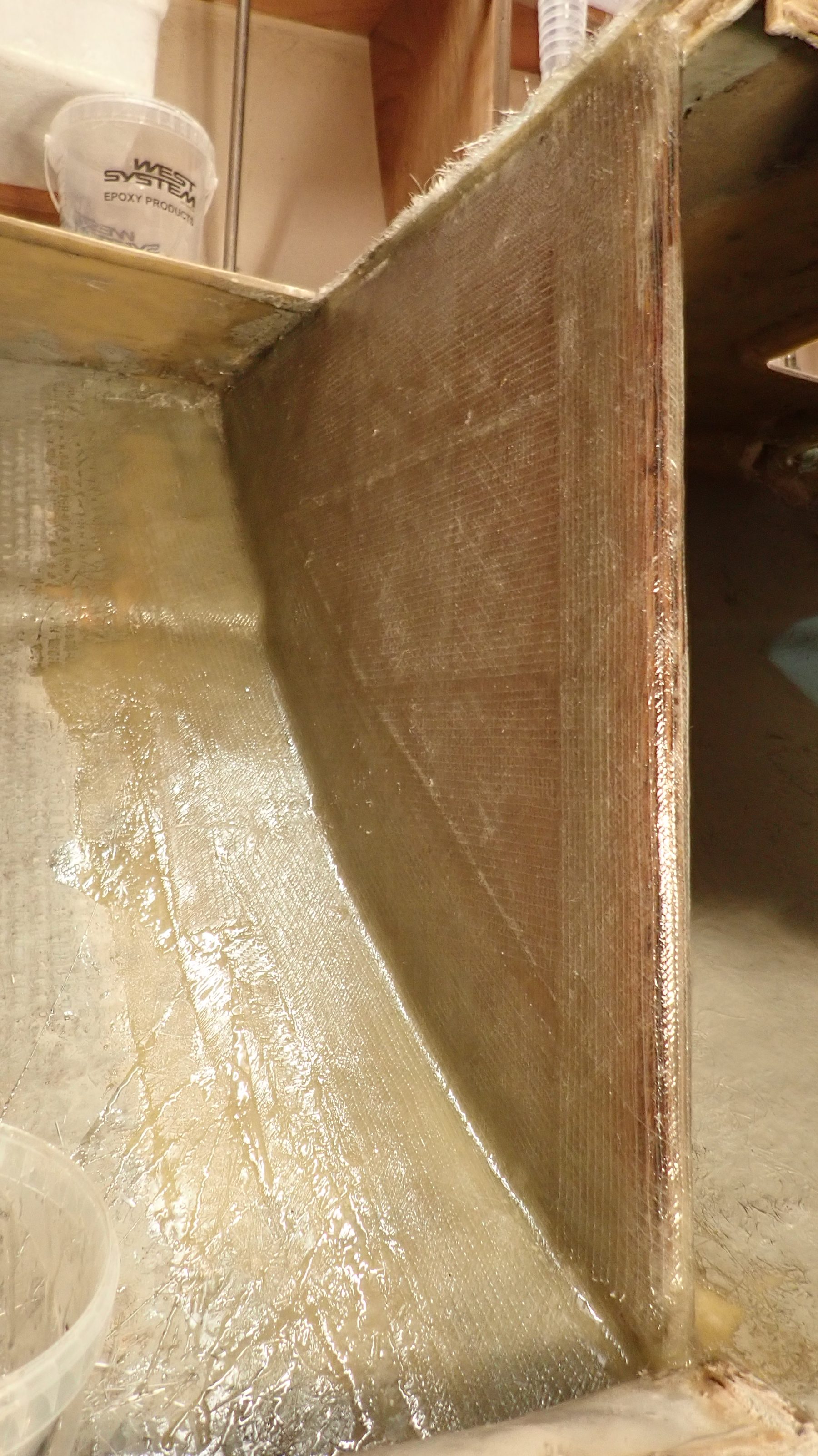
These knees had 2 layers of 250g csm, 7 layers of 450g tape and two layers of 200g biaxial cloth.

7, Final two layers of 250g biaxial woven cloth to consolidate the entire layup.

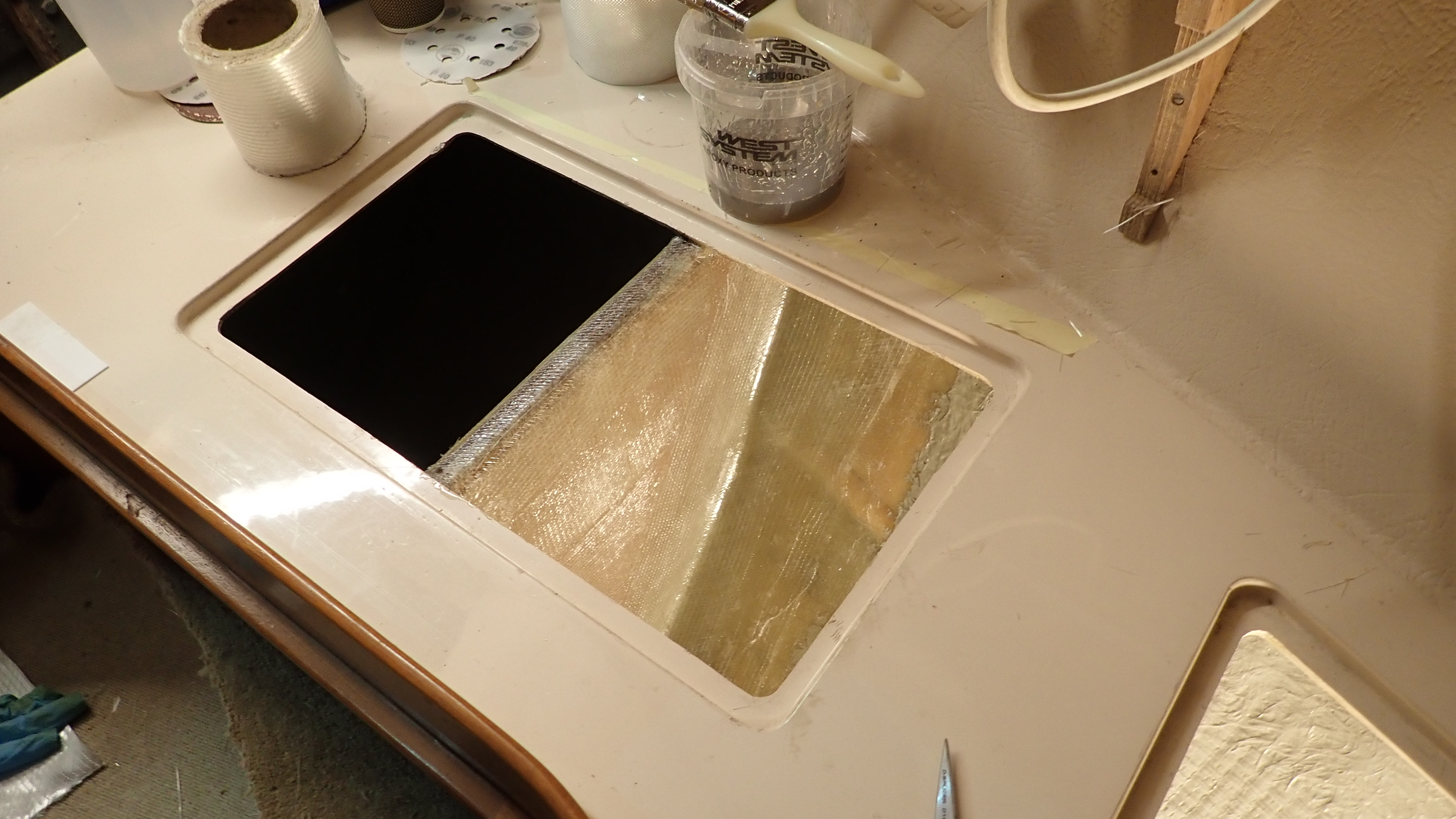
8, Layup fo the forward knee followed the same process but working through a small opening made it trickier.

9, Both knees are now isolated and sealed.

With the structural knees completed, work can move onto rebuilding the locker sides and the under floor support structure.
The manufacture of the grp honeycomb panels is a straight forward process and is ideally carried out on a large bench.
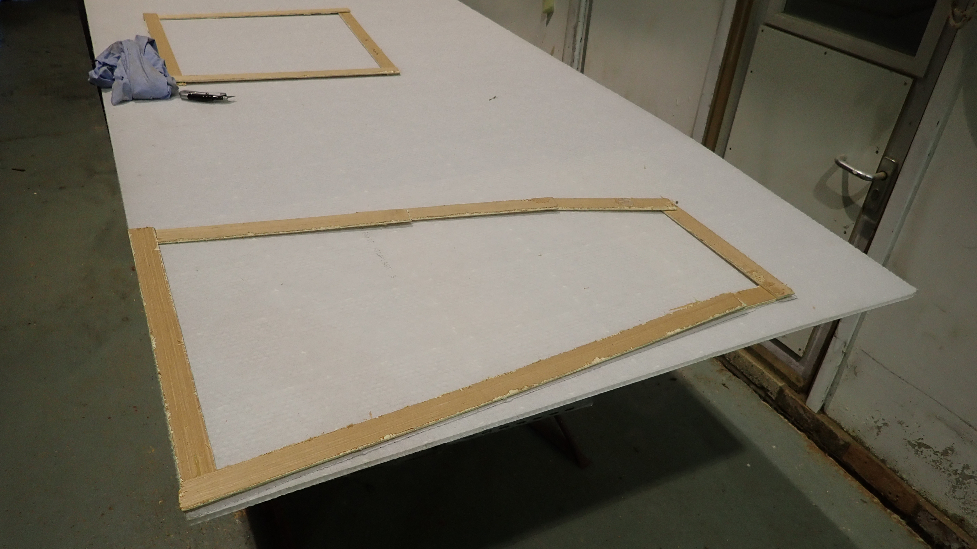
Templates were made for each panel using the harboard strips and glue gun as before.
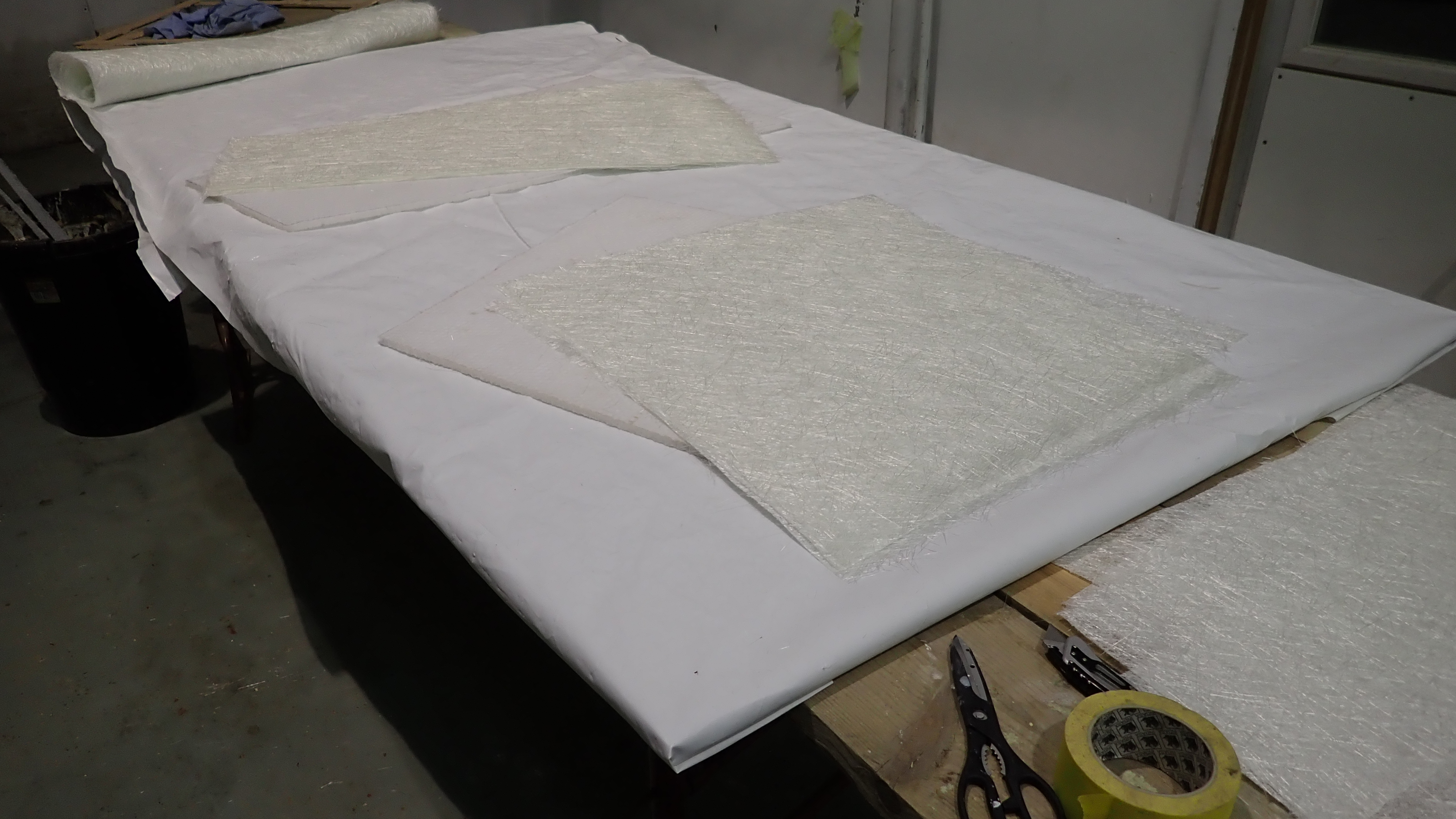
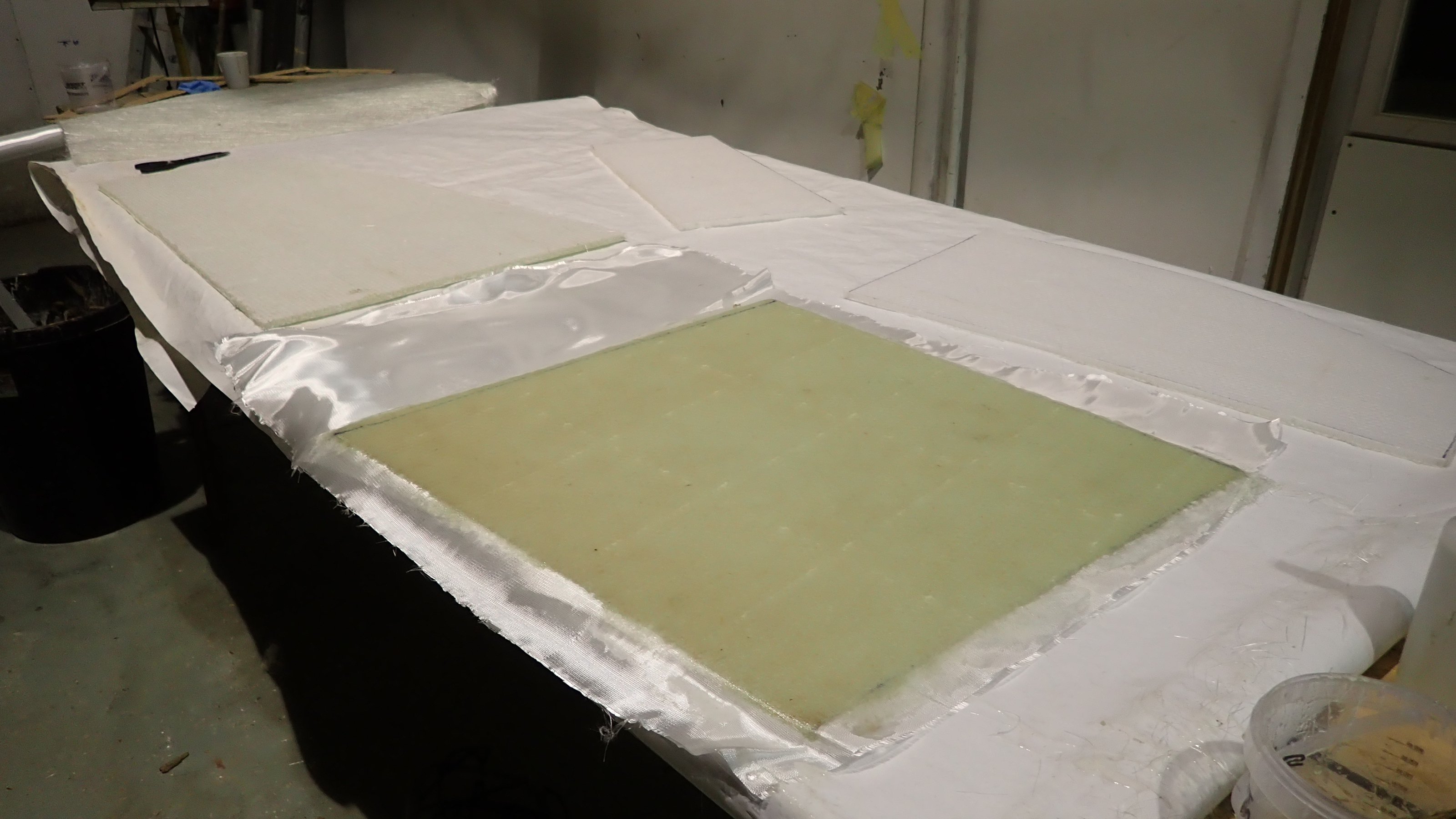
These were then transferred over to the nidaplast board, which in turn were used for patterns to cut out  four layers of 250g csm for each panel.
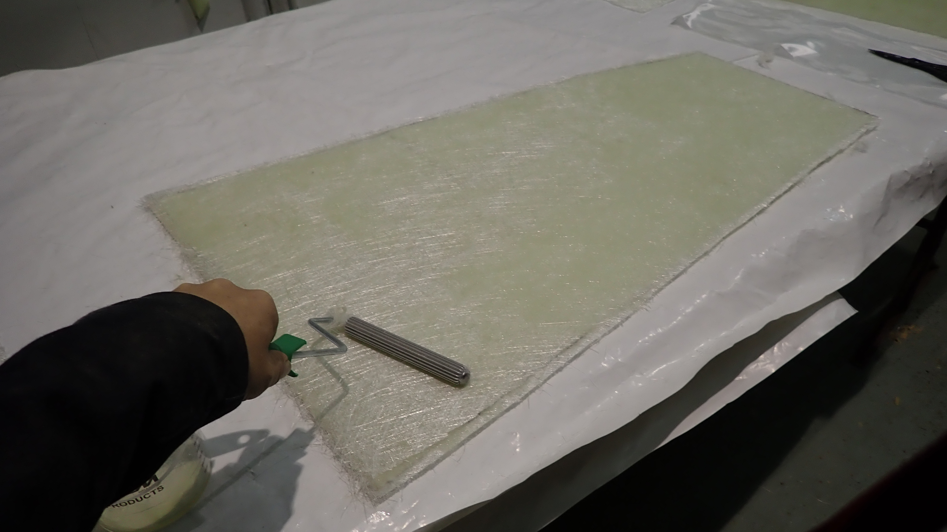
Laying up on a bench is so much easier and much faster so that two layers were applied to one side of the nidaplast before lunch and keeping the temperature up using heat lamps the other side was laminated in the afternoon.
On the inner side of a couple of the locker sides I also applied a layer of tight woven 180g cloth which results in a very smooth surface, which is much nicer than the usual csm finish.

1, Panel templates are transferred over to the Nidaplast core, which are then cut out using a jigsaw.

2, The Nidaplast panels are then used as patterns to cut out layers of csm.

3, Each panel has two layers of 250g csm applied to each side.

4, To get a smooth finish I use a tight woven 180g cloth on top.

Once the honeycomb panels have been trimmed they were all dry fitted to ensure they were the correct size and to establish the order each panel would have to be laminated.
Each panel would have to be laminated around all four edges, on both sides and the only available access was through the locker tops, which resulted in a specific order.
All the panels were made using polyester resin and so I used polyester bonding paste to essentially stick the panels in place.
This bonding paste is fast acting and easy if a little messy to use.
It’s also used for most modern yachts these days to bond the deck to the hull, so its very strong but can be brittle and doesn’t allow flex.
I used four layers of 100mm wide tape for each joint.

1, Dry fitting the under floor panels to check the correct fit.

2, Each panel was glued in place using polyester bonding paste.

3, Four layers of 100mm grp tape was used on each joint on both sides.

4, An access hole was created on the aft panel to give access to the water tank outlet which we had relocated.

The rebuild almost complete the next job was to give all the panels three coats of gelcoat.
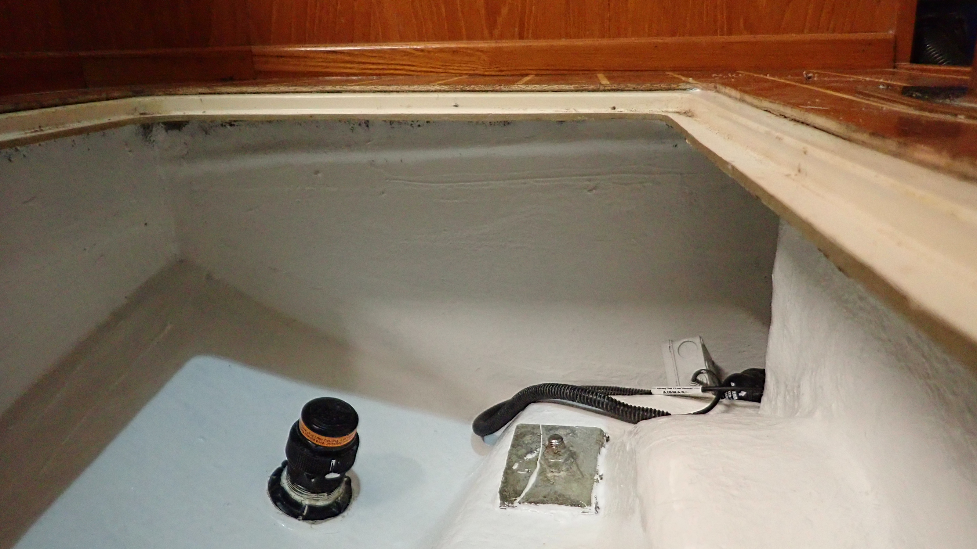
The original colour was bilge grey but in practice we find white is a lot more user friendly, especially when trying to find stuff deep in the bottom of a locker at a later date.
The first two coats were standard white gelcoat and applied using a 3″ brush and the third coat had wax with styrene added so the finish would be non sticky.
24hours later the gel coat was hard enough for us to refit the modified water tank.

1, The first of three coats of white gel coat was applied to the panels and the bilge.

2, Using white gel coat makes the inside of dark spaces far more user friendly.

3, Water tank re fitted, note the new sealed inspection hatch.

4, Easy access now to the tank outlet

The chain plates were then re fitted using new 316 stainless backing plates and new M12 shouldered stainless bolts with nylock nuts.
The old chainplate bolts were machine screws and threaded all the way which is not good practice as water can draw up through the thread and rot the inside of the knee and also if there is any movement the thread can cut the hole sides like a hacksaw.
The transducer cables were re routed and all the keel bolts given a once over whilst we were there.

1, Chain plate fitted with stainless backing plates and shouldered bolts with nylock nuts.

2, Transducer cables re routed and keel bolts checked.

This job was a real eye opener to me.
Normally you get a clue or two once stepping on board on whether there is a likelihood to be any rot about.
There’s a kind of smell, an aura, a general feeling that something ain’t right.
However in this case it was a total surprise, given how immaculate and well looked after the boat appeared to be.
Still not found the fluxgate compass and I’m not at all sure how keen the customer is for me to keep looking!
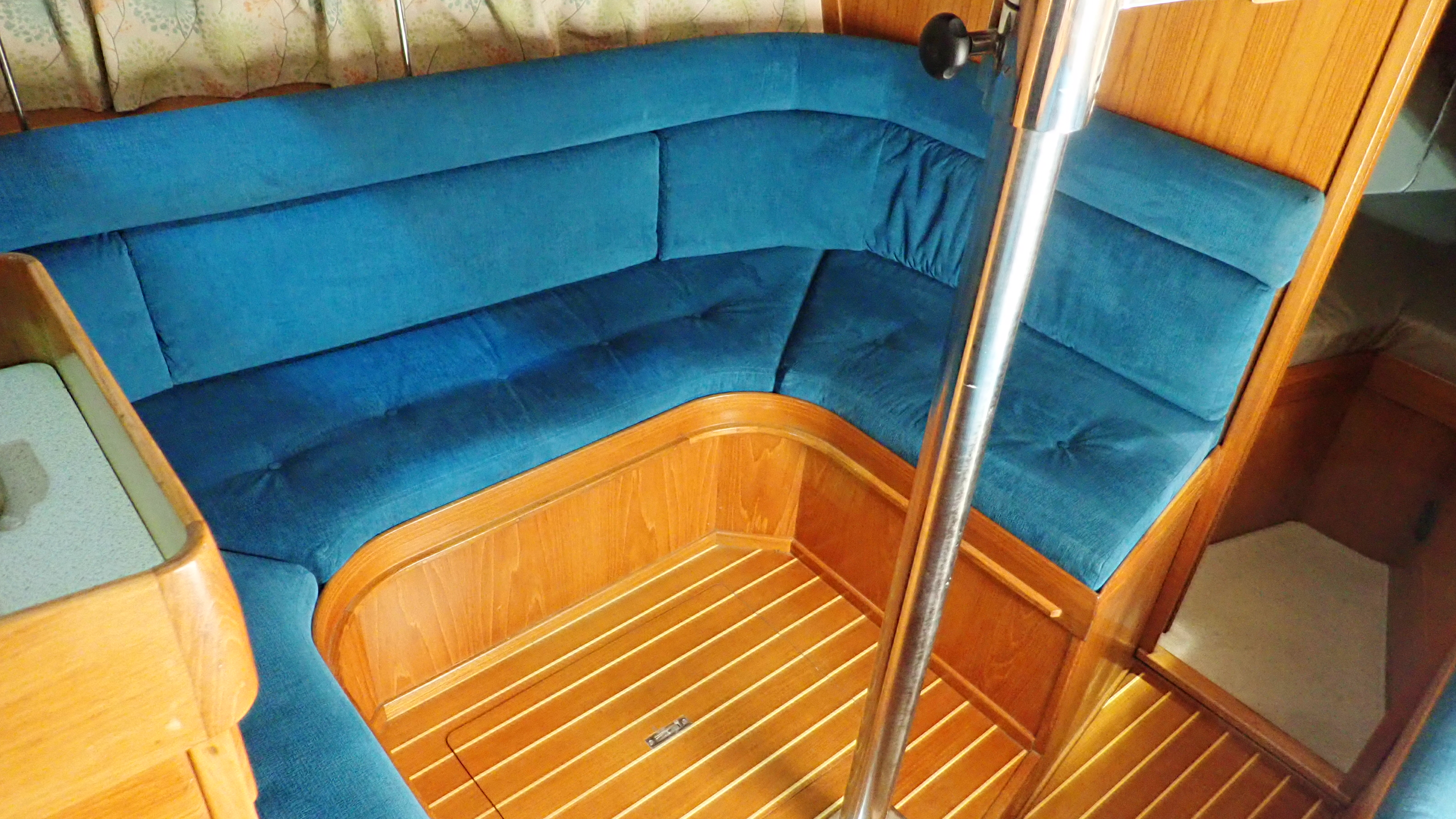
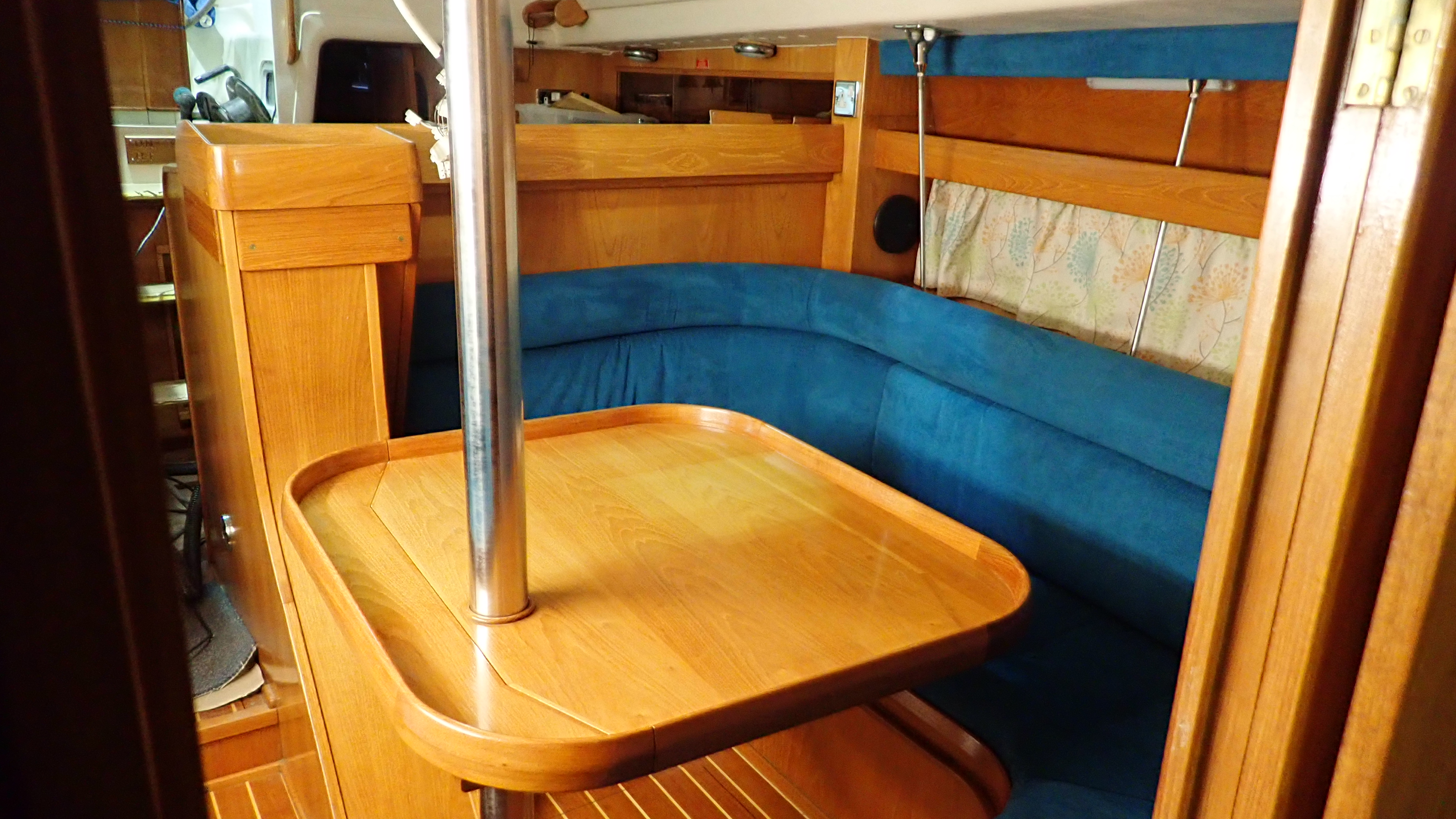
All back together and looking the same as it did when I started.

By | 2018-01-21T17:07:42+00:00 December 18th, 2017|Uncategorised|Comments Off on Very nice but rotten

Prop issues

This time of year, when the boats out of the water for the winter, is a great time to check the condition of your boat’s anodes, cutlass bearings, shaft and prop for the coming season.
Anodes are often overlooked and sometimes considered to be of a low priority.
Merely talking about anodes can be confusing with numerous books written on the subject and many, at times conflicting, ideas and guides provided.
The sad fact is that if you avoid looking after your anodes correctly, the consequences can cost a fortune to put right.

As a boat owner myself I don’t like spending money if I can help it, especially on something that is designed to dissolve away to nothing.
The temptation therefore is to spend less and buy cheaper anodes that coincidentally happen to dissolve slower.
Do NOT do it.
The simple truth is that its far better to spend money on quality anodes that work correctly than have to pay for a new prop, shaft or sail-drive leg.
With wooden boats, you also need to be aware and guard against the potential of electrochemical decay of your timbers.
We’ve seen cheap anodes that customers have fitted, usually sourced via ebay or similar, that frankly have not worked.  Often they look just as good after a season as they did when first fitted, which is obviously a bad thing.

As a general rule the larger the surface area the higher the current capacity or galvanic voltage it can handle.
The heavier the anode the longer it will last.
The higher the purity of Zinc the more efficient it will be.

On a grp boat its preferable to link or ground your anode internally to the propshaft.
Some manufacturers ground out the anode on the engine block or engine mounts but quite often the prop shaft is electrically isolated from the gearbox and engine using plastic bushes and inserts, rendering the connection pointless.
Some Volvo gearboxes, for example, use an internal copper pipe matrix for cooling and to avoid corrosion they are electrically isolated from the engine and add a less than helpful notice on the gearbox, “Do Not Ground”.
In these cases, if there is no room for an external shaft anode, you must ground directly to the shaft using an Electro-Eliminator from MgDuff or similar system.
On an Ovni we discovered that the grounding wires were linked through the boat’s main isolators, which meant that leaving the boat and turning off the isolators,  would also inadvertently turn off the grounding wire to the anodes. Also not very helpful, especially on a aluminum hull.

Most of the folding and feathering props have their own specific anode but this is really only there to protect the prop and not the shaft and P bracket.
These prop anodes are often quite small and normally these won’t last more than a season and in some cases only 6 months.
Quite often when we lift a boat out, the prop anode will have gone completely.
This is normally due to the anode dissolving around the fasteners and simply dropping off.
A tip here is to dab a blob of antifoul round the fastening bolts so that the anode round the bolt does not dissolve. Alternatively, you can use plastic fasteners instead of the often supplied Stainless ones.
Work on the basis that the prop anode is just looking after the prop.
Anything else, such as the Propshaft, Propshaft tube, P bracket and even below water line pintle and gudgeon, will need their own local anode protection.

Usually a decent sized shaft anode will do the trick and avoid the hassle of internal linking.
This is also a favourable method with wooden boats as there is a possibility that any exposed wet wood between a linked anode and the protected metal object, can effectively close the circuit which will result in electrochemical decay: rot in other words.

If you keep your boat in a marina, hooked up to shore power, then I’d highly recommend you fit a galvanic isolator to guard against stray electrical currents.
Your boat may be just fine with no stray outputs, but the boat two berths down could easily be fizzing your anodes away.
For those of you with aluminium boats or a sail-drive unit this really should be a priority.

When we lift a boat out I usually grab hold of the prop and give it a good tug, side to side, up and down.
Any movement lateral movement here means that the cutlass bearing needs changing.
If it’s not changed you will experience vibration under load and when reversing you will be able to hear and feel some knocking.
The wear will increase and you run the risk of damaging the engine coupling and propshaft seal and if fitted with a folding or feathering prop, you will wear out the moving parts very quickly.
We find that many boats fitted with folding props, especially the Auto Prop, tend to wear out the cutlass bearing faster than a conventional fixed prop.
Our theory is that each time you move from forward to reverse the prop changes angle abruptly and this rapid change contributes to increased cutlass bearing wear.
Changing the cutlass bearing can range from a 15 minute job to a full days nightmare depending on configuration and with so many different types and styles its really beyond this article to offer much advice.

Stainless steel propshafts are usually pretty resilient.
However we’ve seen our fair share of broken ones and others that have been almost cut through by, believe it or not, old fishing line.
If there’s a problem it’s usually where the shaft exits the hull but most fail around the key-way where the prop locates.
Its worth popping the prop off and periodically checking that the key is in good condition and that it’s a nice tight fit with no lateral movement.
Fixed props are easy to check and usually it’s just a matter of inspecting the blades for pitting and that the edges are clean and fair, the locking nut is torqued up correctly with a locking pin in good condition and ensuring the boss is fully home on the taper and key-way.
Ensure the key is fully set down into the shaft key-way and that there’s no grit or muck under it.
The danger is that the prop will tighten up on top of the key and not sit completely down onto the taper.
Check for an air gap above the key if you can.

We had a situation a couple of years ago where the propshaft key had sheared.
All seemed fine ashore. When the boat was launched all appeared good whilst in forward gear, as the prop was pushed hard against the taper.
However putting the boat hard into reverse broke the taper and the shaft just span round with the prop essentially stationary. So it can and does happen.

Folding and feathering props are somewhat more complicated as many have a lot of moving parts that will wear out and some have internal rubber bushes that can fail.
I know this to my cost as the vulcanised rubber bush inside my Gori two bladed folding prop decided to come adrift of the main hub, just as the new season had started.
This had to be sent back to the manufacturer in Denmark who then sent it on to somewhere in Belgium to be repaired. They, in turn, sent it back to Denmark again before returning it to me with a bill for £450 for the privilege, losing me a quarter of the season – not that I’m bitter or anything.

Most manufacturers sell full service kits for the types that use bearings such as the Auto prop from Bruntons.
It’s a straight forward process to replace the bearings and the hardened bearing races, then setting up the blade torque required.
The Max prop is a little more complicated as you’ll need to note down the corresponding letter marked on the hub to maintain the correct blade angle.

One of the more satisfying jobs is cleaning up a dirty prop.
My usual process is to start by cleaning off most of the stubborn muck using a wire cup brush on a drill.
This is followed by 600 and then 1000 grit wet and dry sandpaper, finishing off with cutting compound and a buff and often the final result is as good as new.

Over the past few years we’ve fitted a lot of Feather stream props from Darglow, who I may say are an excellent company to deal with and so far we’ve had few problems other than the usual stupidly small prop anodes they come with.
If you’re in the market for a prop you can phone them, tell them your boat make, displacement, engine size and importantly the gearbox number and they will tell you what size and pitch prop you will need and so far they have been spot on every time.
A year of so ago we carried out a prop switch from a fixed to a feathering prop. During the process, based on the gearbox number,  Darglow pointed out that the original right handed fixed prop should have been a left handed one.
Funny to think the owner had only recently finished a trip to Cape Horn and back, it now appears that he did a fair chunk of the journey in reverse!
[siteorigin_widget class=”WP_Widget_Media_Image”][/siteorigin_widget]
[siteorigin_widget class=”WP_Widget_Media_Image”][/siteorigin_widget]
[siteorigin_widget class=”WP_Widget_Media_Image”][/siteorigin_widget]
[siteorigin_widget class=”WP_Widget_Media_Image”][/siteorigin_widget]
[siteorigin_widget class=”WP_Widget_Media_Image”][/siteorigin_widget]
[siteorigin_widget class=”WP_Widget_Media_Image”][/siteorigin_widget]
[siteorigin_widget class=”WP_Widget_Media_Image”][/siteorigin_widget]
[siteorigin_widget class=”WP_Widget_Media_Image”][/siteorigin_widget]
[siteorigin_widget class=”WP_Widget_Media_Image”][/siteorigin_widget]
[siteorigin_widget class=”WP_Widget_Media_Image”][/siteorigin_widget]
[siteorigin_widget class=”WP_Widget_Media_Image”][/siteorigin_widget]
[siteorigin_widget class=”WP_Widget_Media_Image”][/siteorigin_widget]
[siteorigin_widget class=”WP_Widget_Media_Image”][/siteorigin_widget]
[siteorigin_widget class=”WP_Widget_Media_Image”][/siteorigin_widget]
[siteorigin_widget class=”WP_Widget_Media_Image”][/siteorigin_widget]
[siteorigin_widget class=”WP_Widget_Media_Image”][/siteorigin_widget]
[siteorigin_widget class=”WP_Widget_Media_Image”][/siteorigin_widget]
[siteorigin_widget class=”WP_Widget_Media_Image”][/siteorigin_widget]

By | 2017-12-12T23:09:19+00:00 December 11th, 2017|Uncategorised|Comments Off on Prop issues