Herroshoff


You’ve heard the story before when a guy goes to the doctor for simple pain in the chest that he’s sure is indigestion and ends up with a heart transplant?
Well this story is a little like that and frankly could have ended up just as deadly if no action had been taken.
Firstly I need to apologise for the quality of some of the photos.
Most were taken down a very dark hole, in the deepest recesses of a Island Packet 29.
A yacht that I had previously held in high esteem, as a “a quality product that won’t let you down, sir”.
From this point on I will not be as generous with my praise about this class.
Anyway the owner had noticed a rumble when under power and we decided that it sounded like the cutlass bearing was on its way out.
We said we’d check it out when the boat gets lifted.
So out she came and sure enough the shaft was wobbling about.
A new cutlass was ordered and an apprentice was instructed to take the prop off, undo the lock screws and pull the cutlass bearing out of the tube.
After a short time the apprentice sought me out saying that one of the locking grub screws wouldn’t come out and “Should the stern tube be wobbling about?”
Now if you happen to own a IP29 and are of a sensitive nature I urge you to grab a stiff drink.
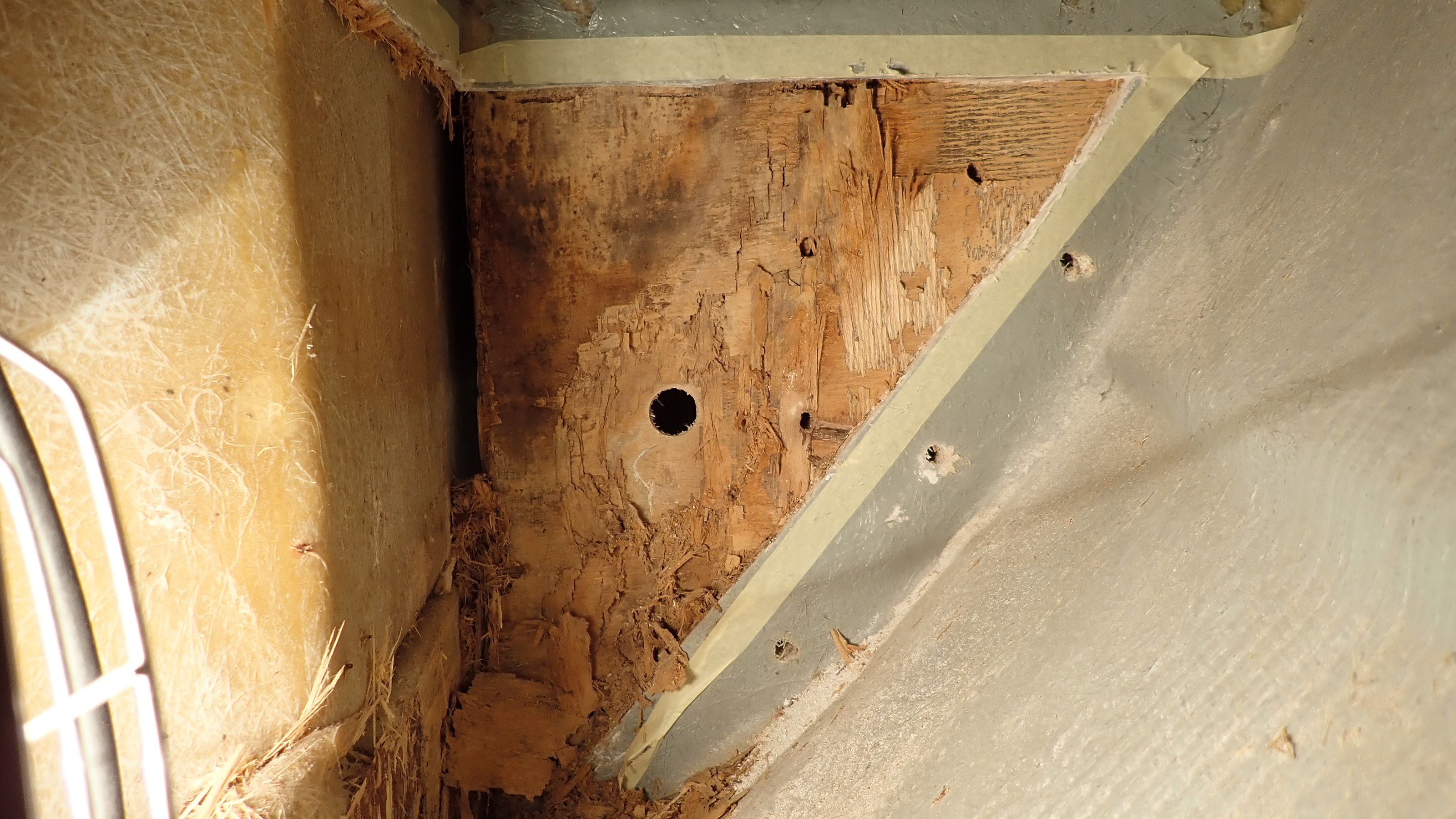
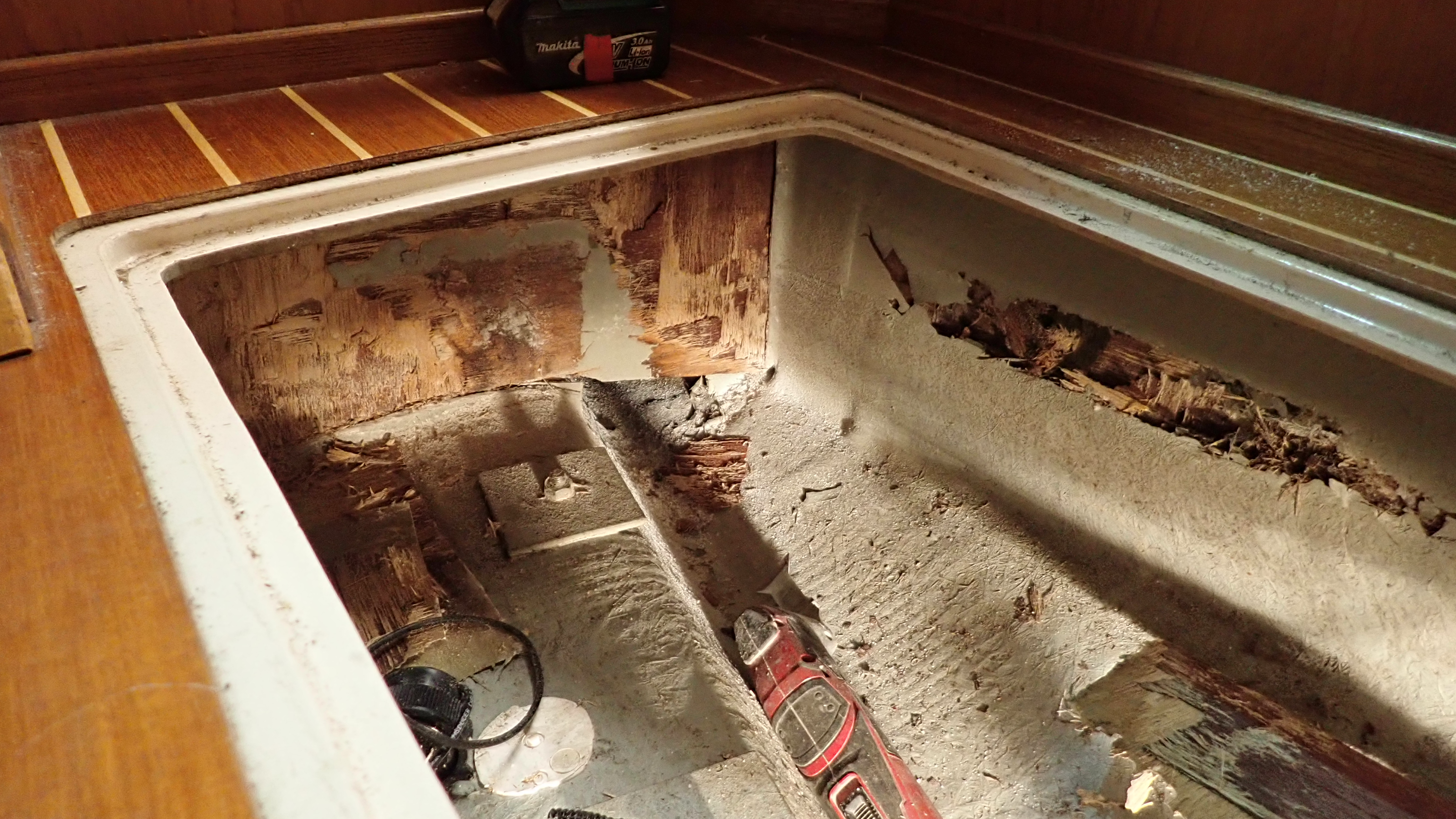
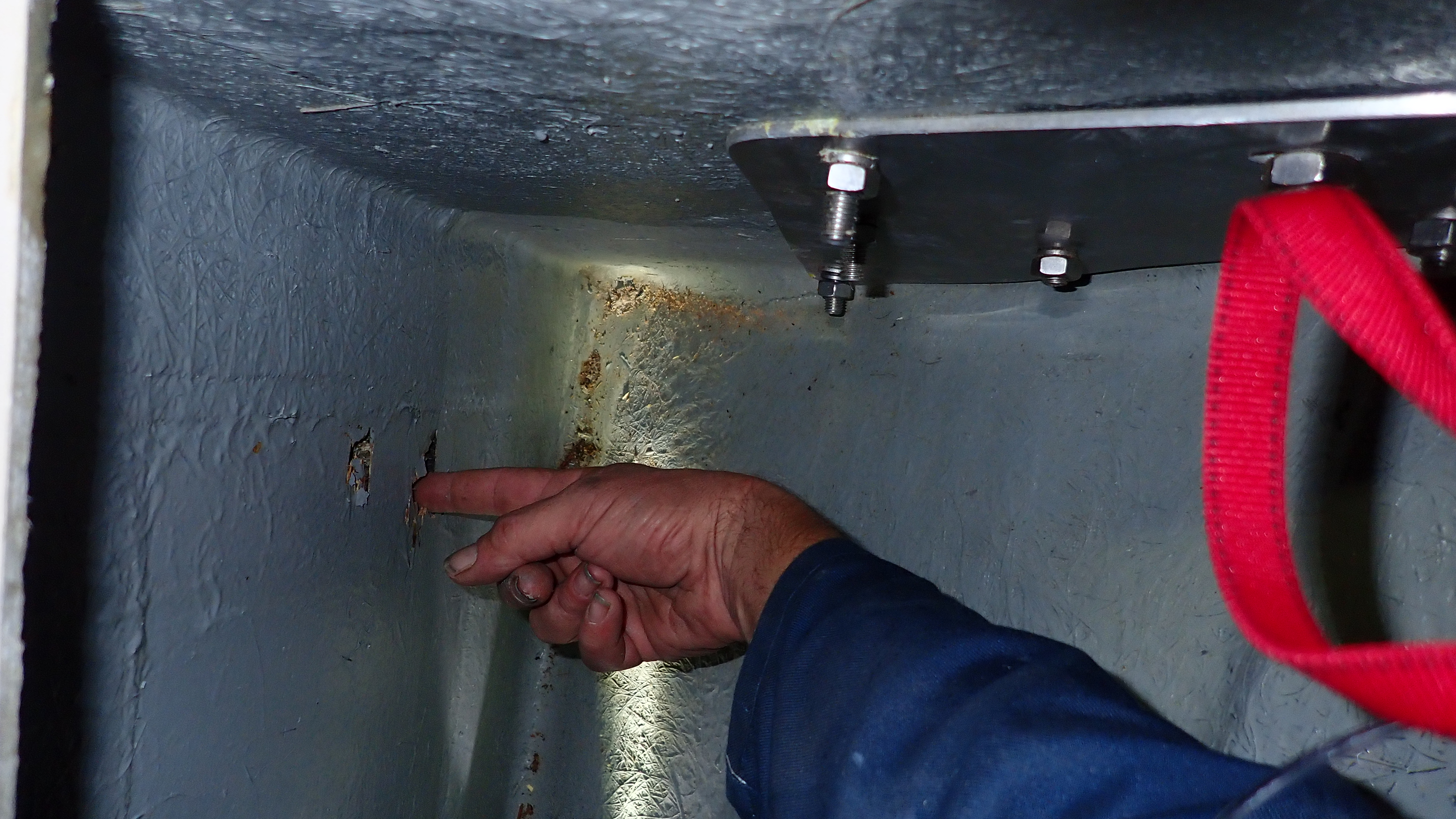
The reason the tube was indeed wobbling about was because there were just two bolts, threaded all the way I might add, with nylock nuts.
No washers, no backing plates.
The hollow grp keel through which it was bolted was only 12mm thick, however where the nuts had been tightened they had compressed the grp to such an extent that the lower hole had compressed to nothing.
Not only that but there was no other internal support for the tube, even at the stern gland.
Keep in mind that the 1” dia shaft runs around 5’ between the skeg and the engine coupling.
Having no internal support for the prop shaft tube or shaft is asking for trouble.
In our view, catastrophic failure was only a question of time.
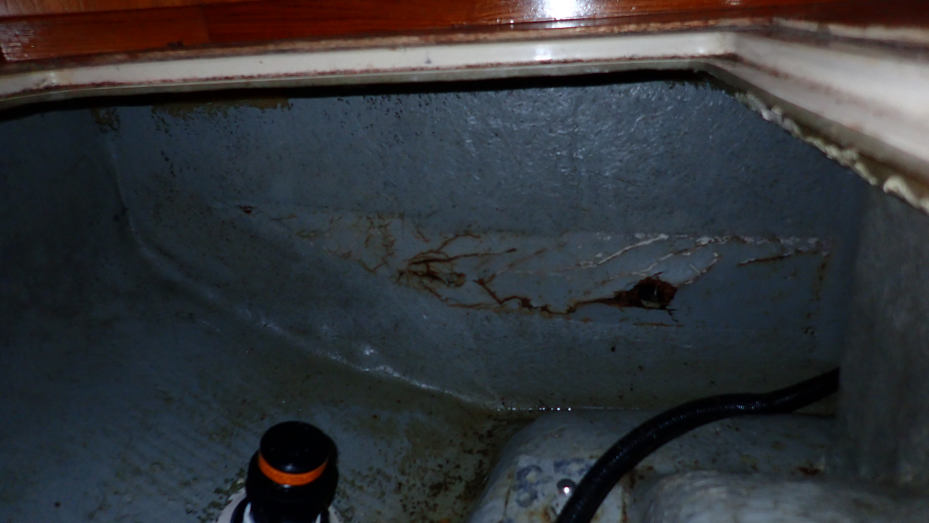
The first indication of trouble would be water in the bilge, which given her design, it would have been quite difficult to trace.
If this were a car, we’d be demanding an immediate recall or at the very least, an immediate inspection.


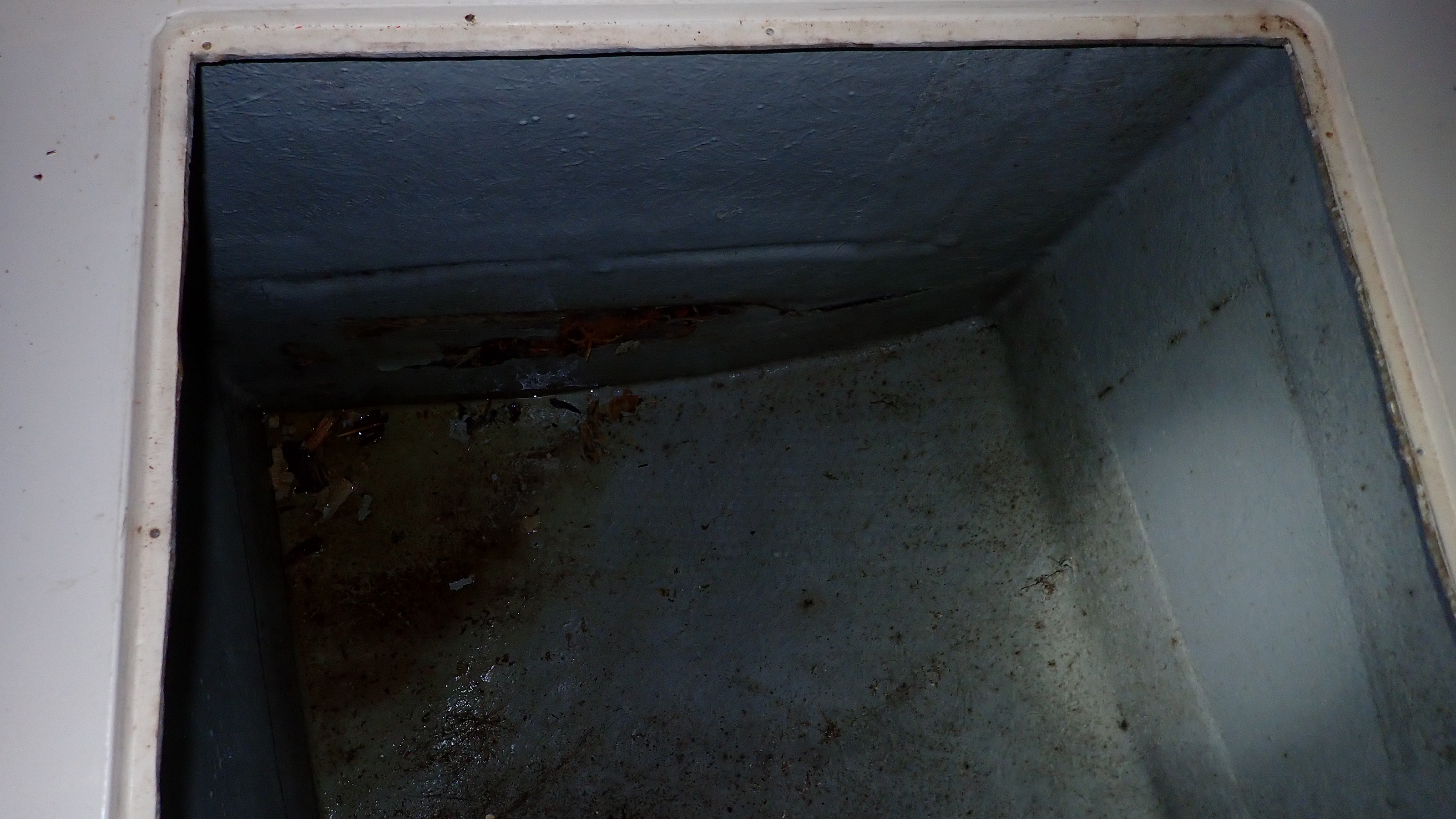
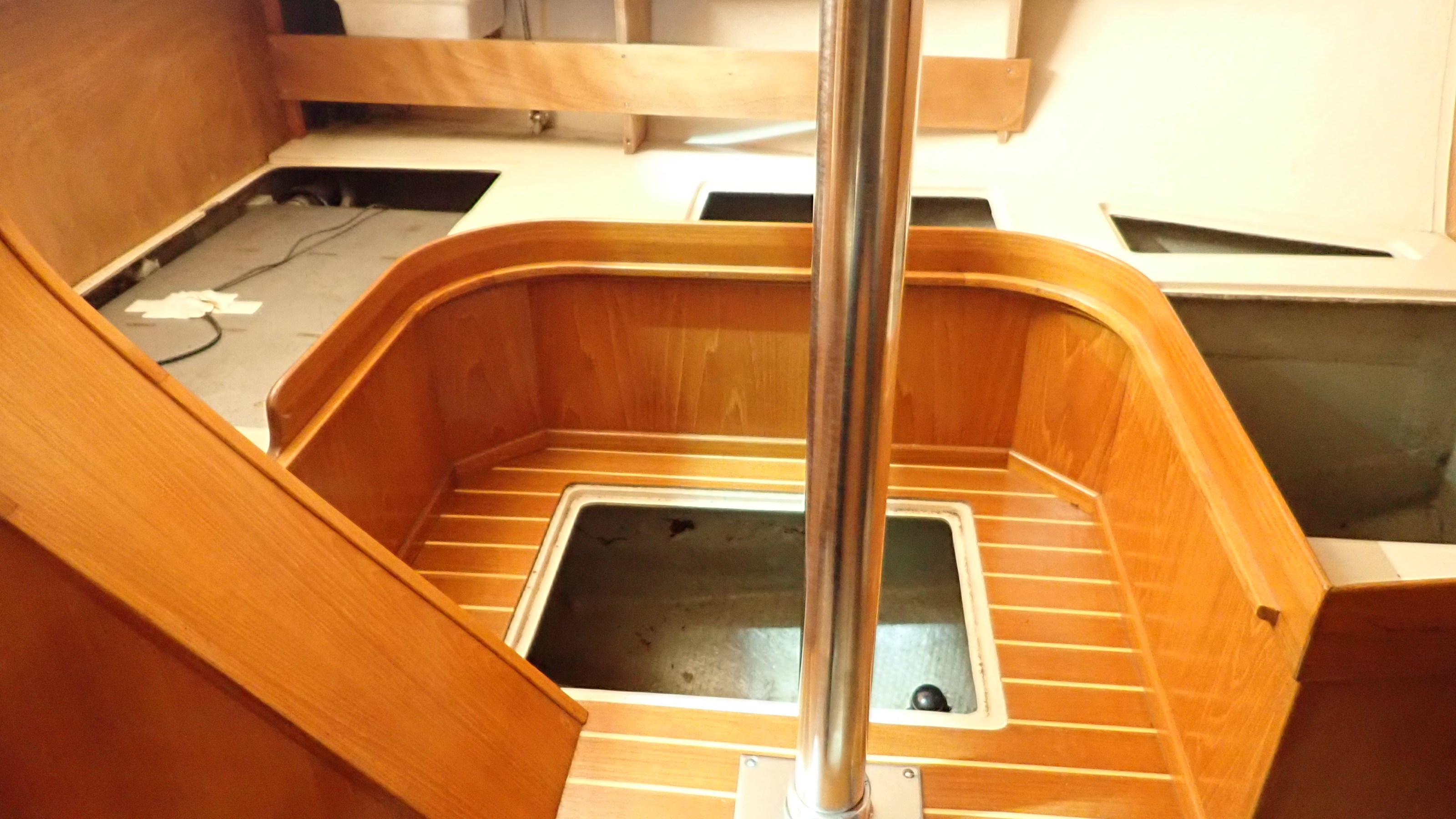
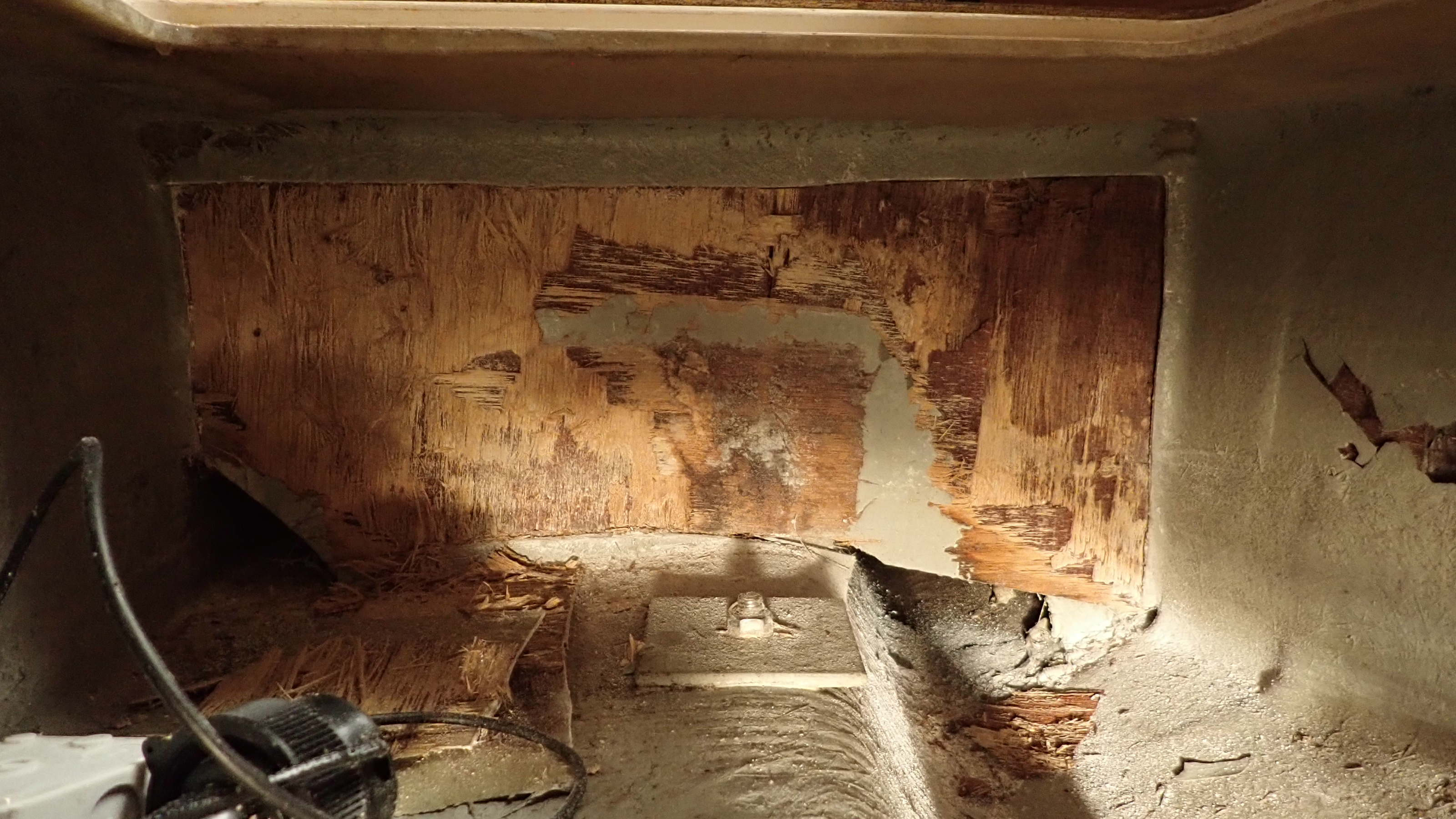
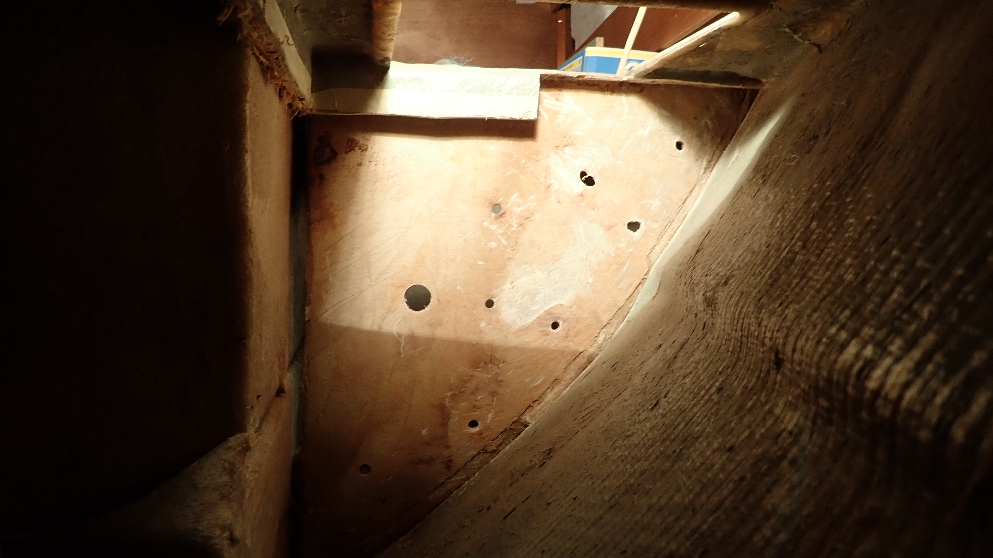
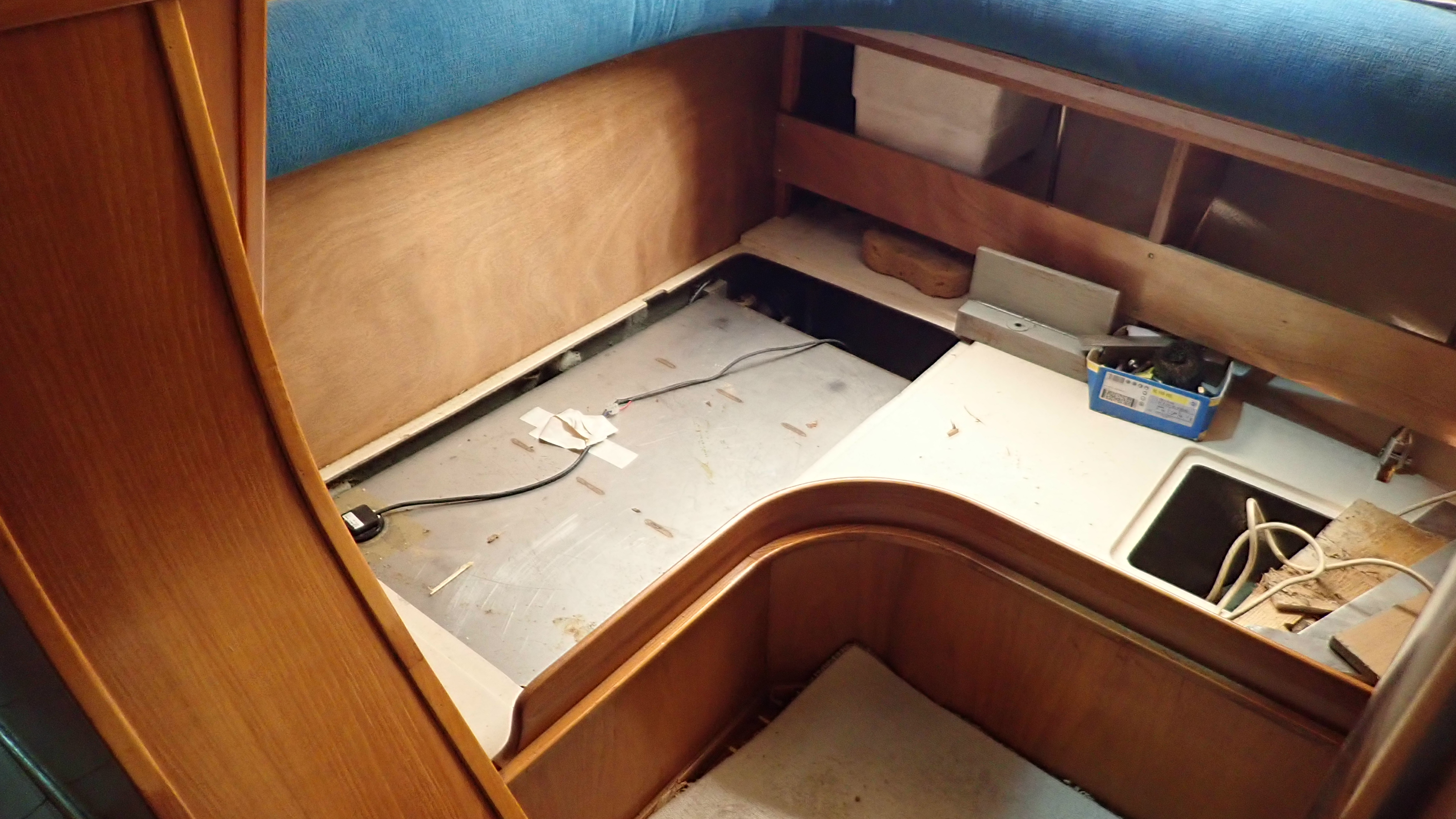
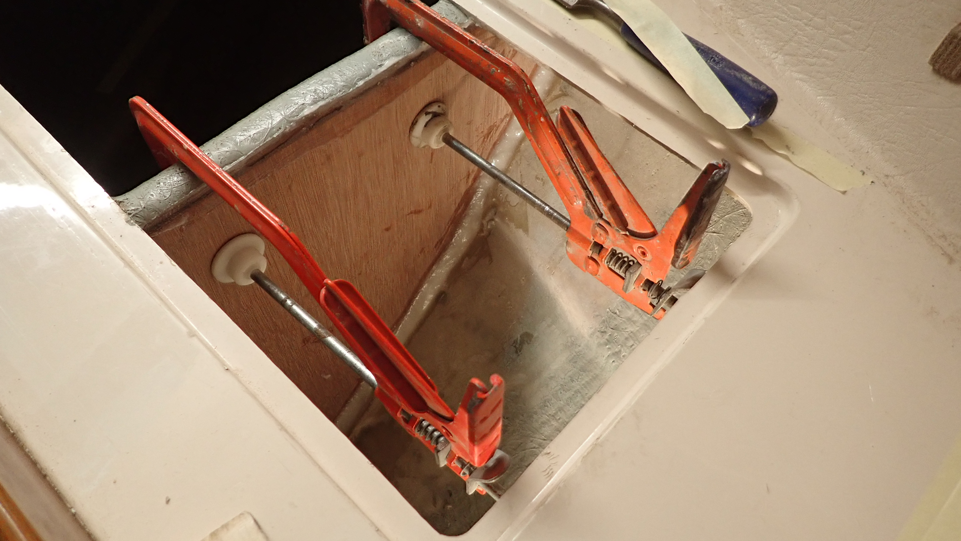
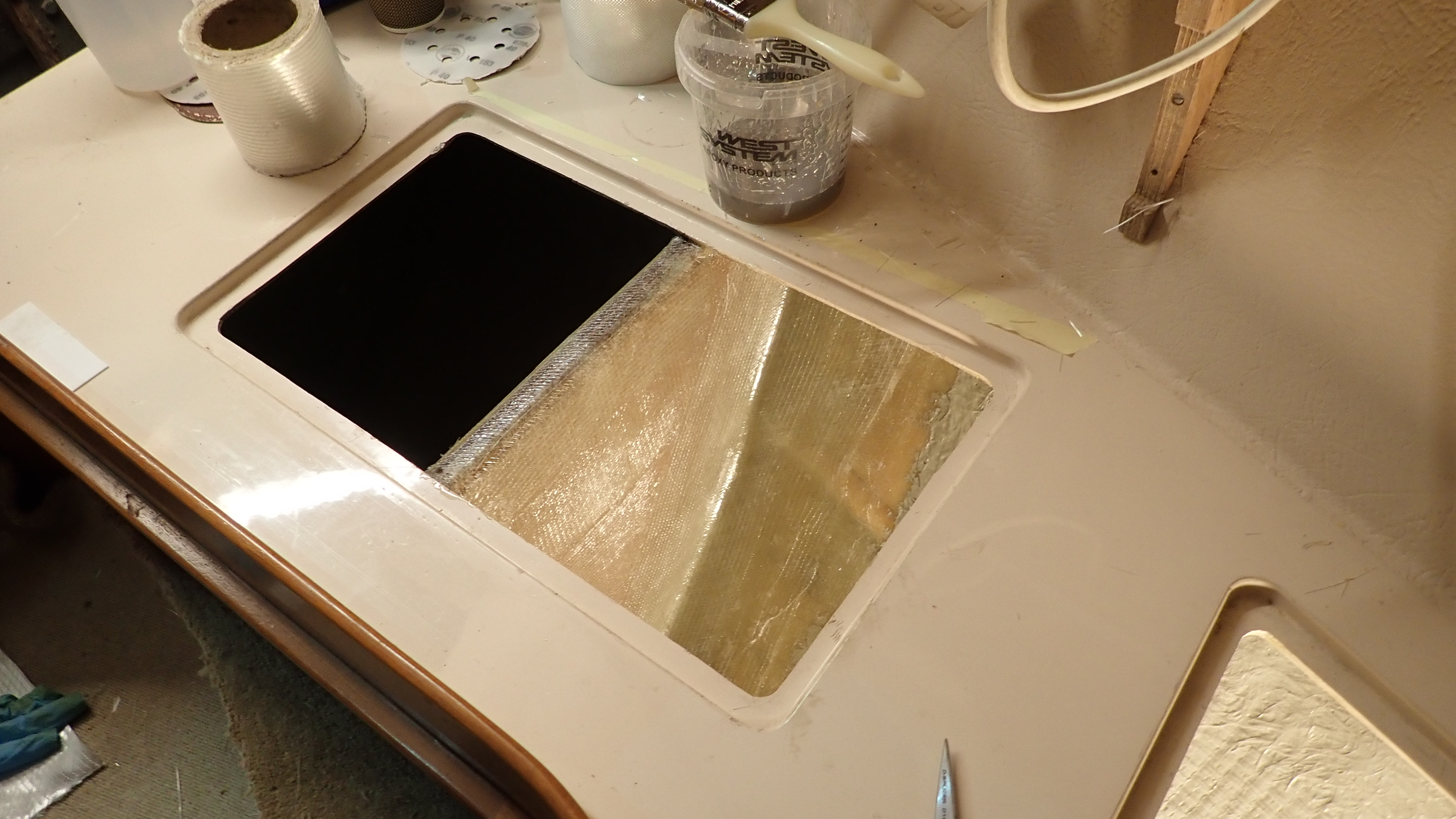
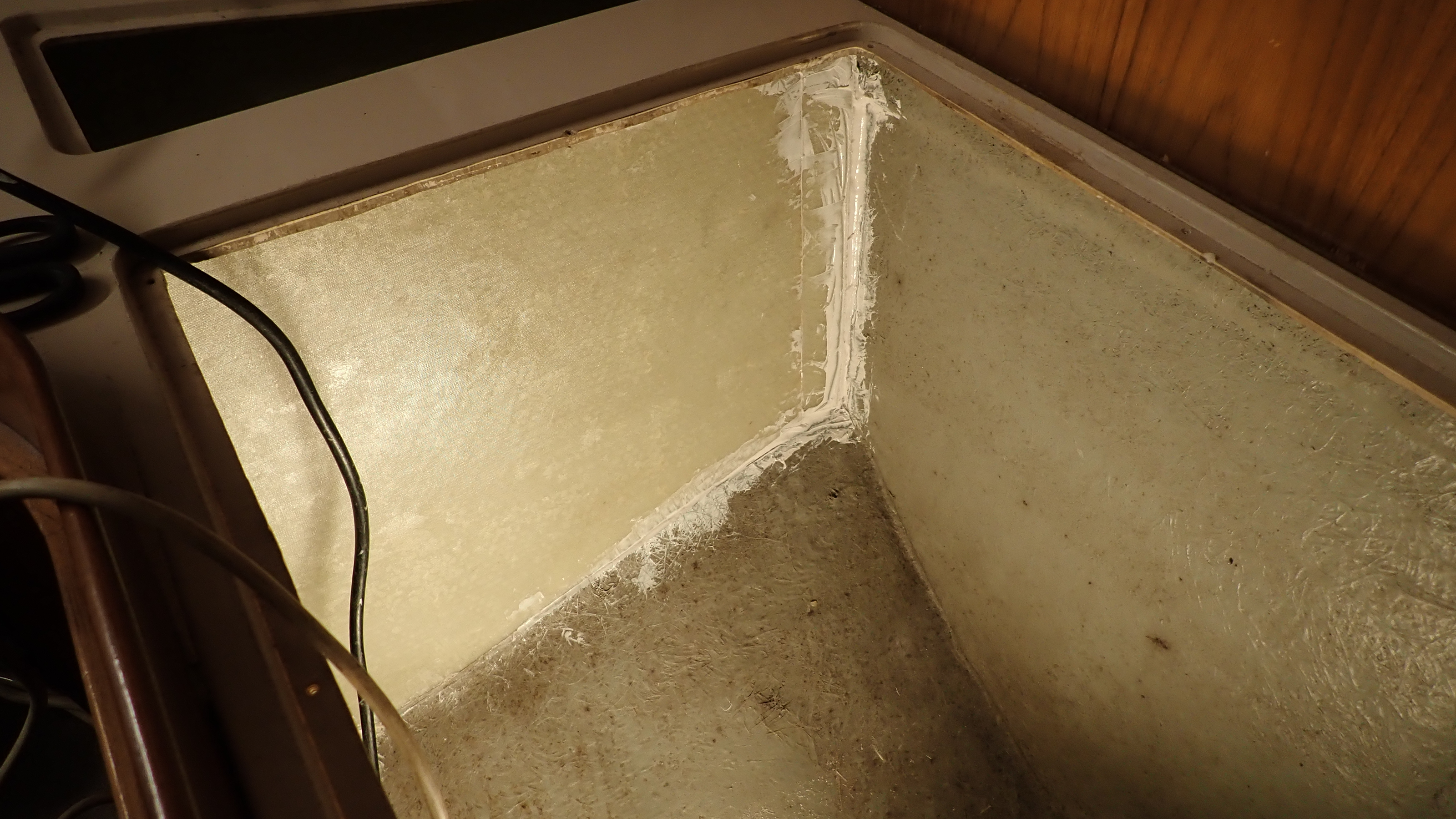
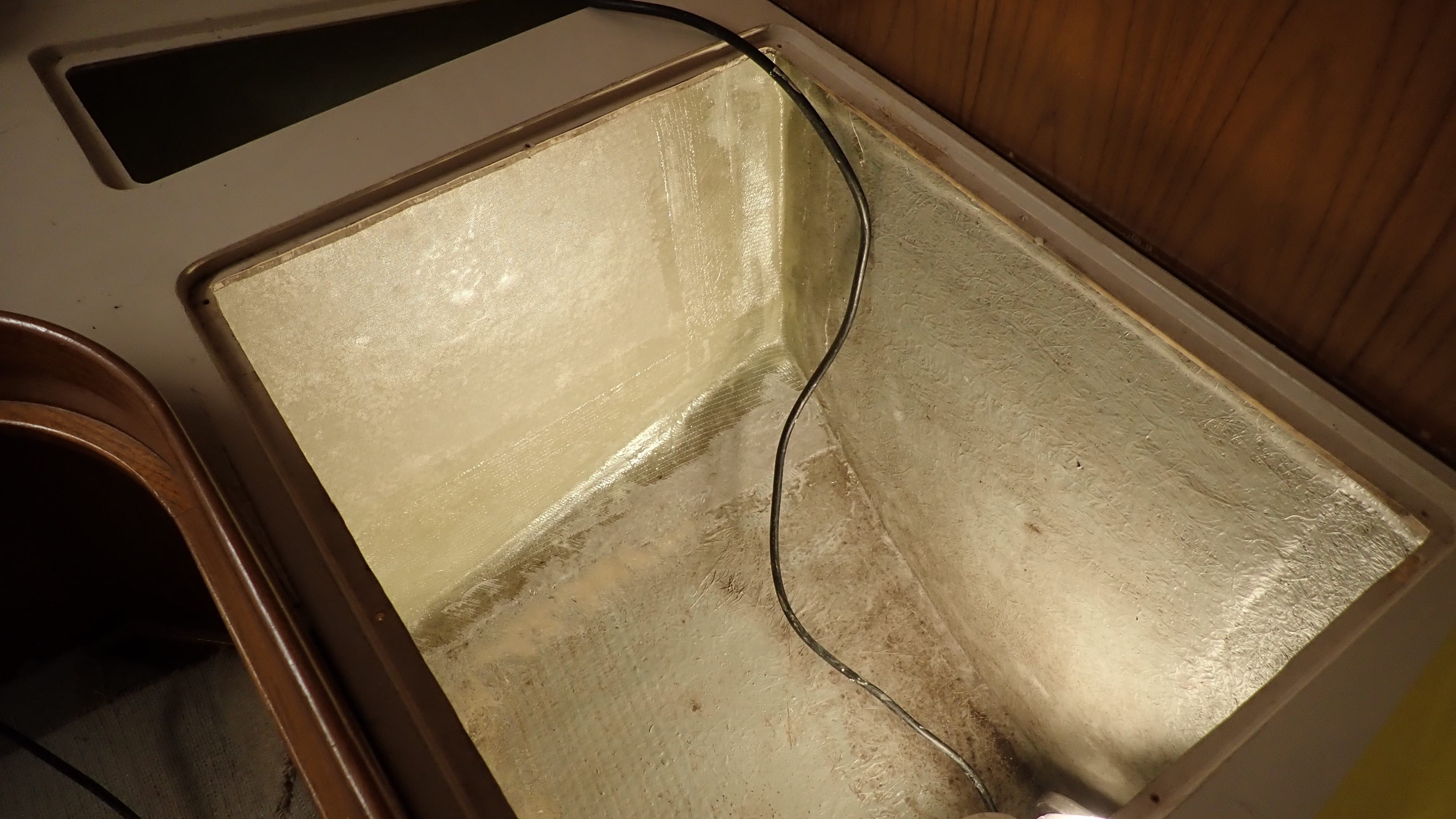
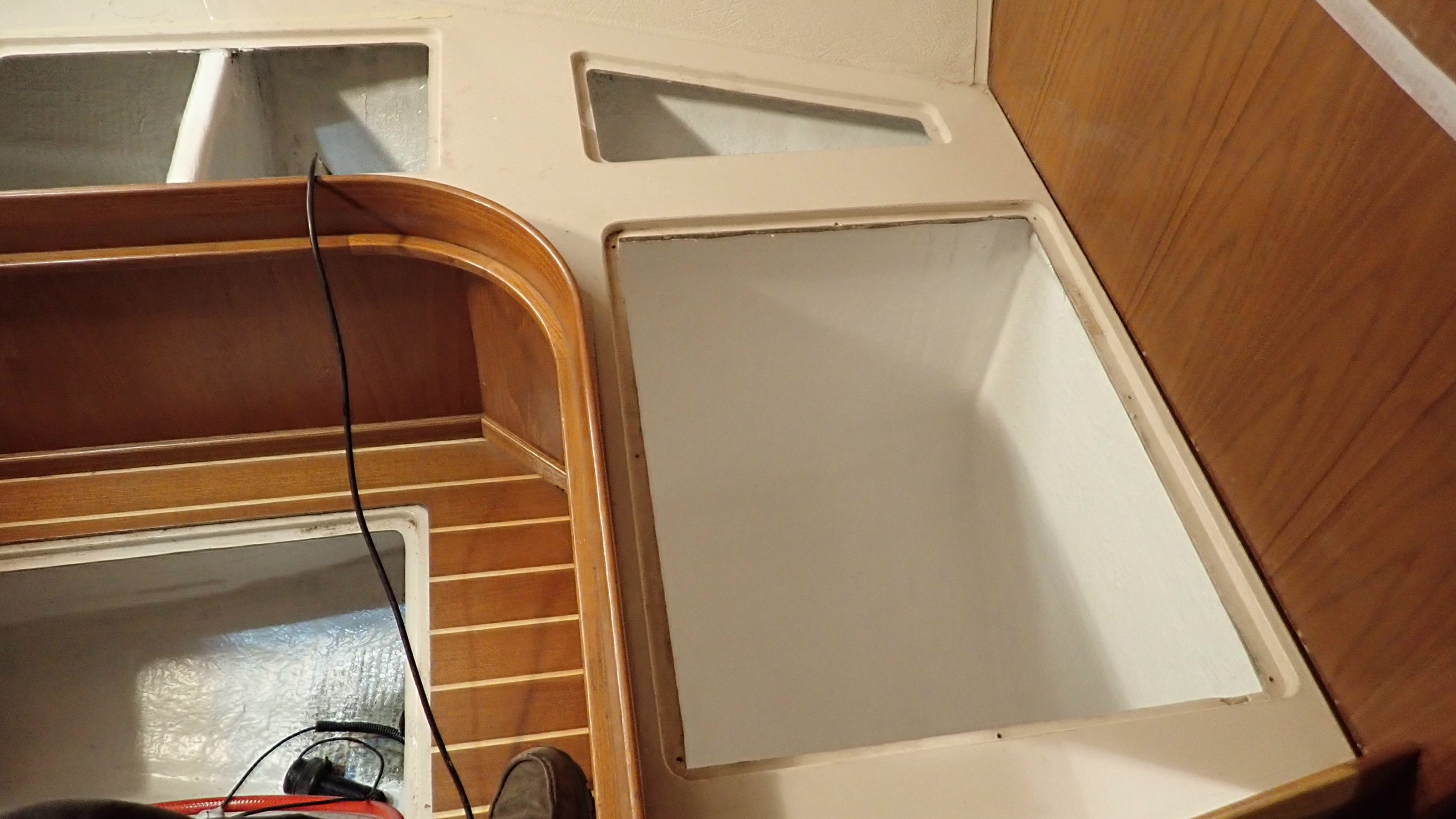
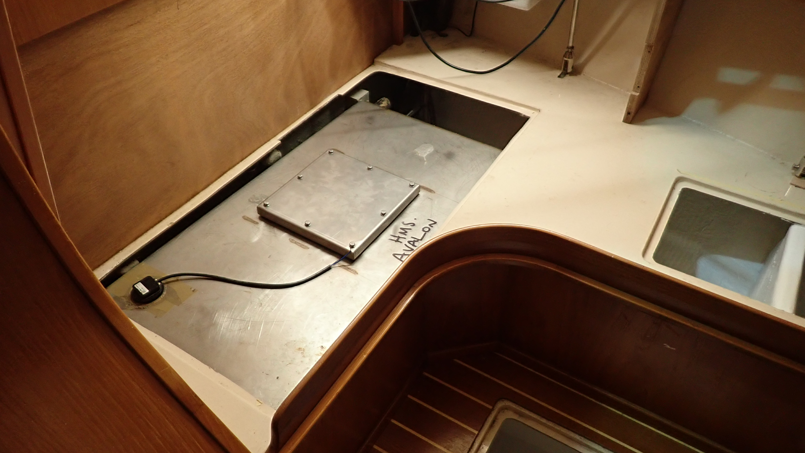
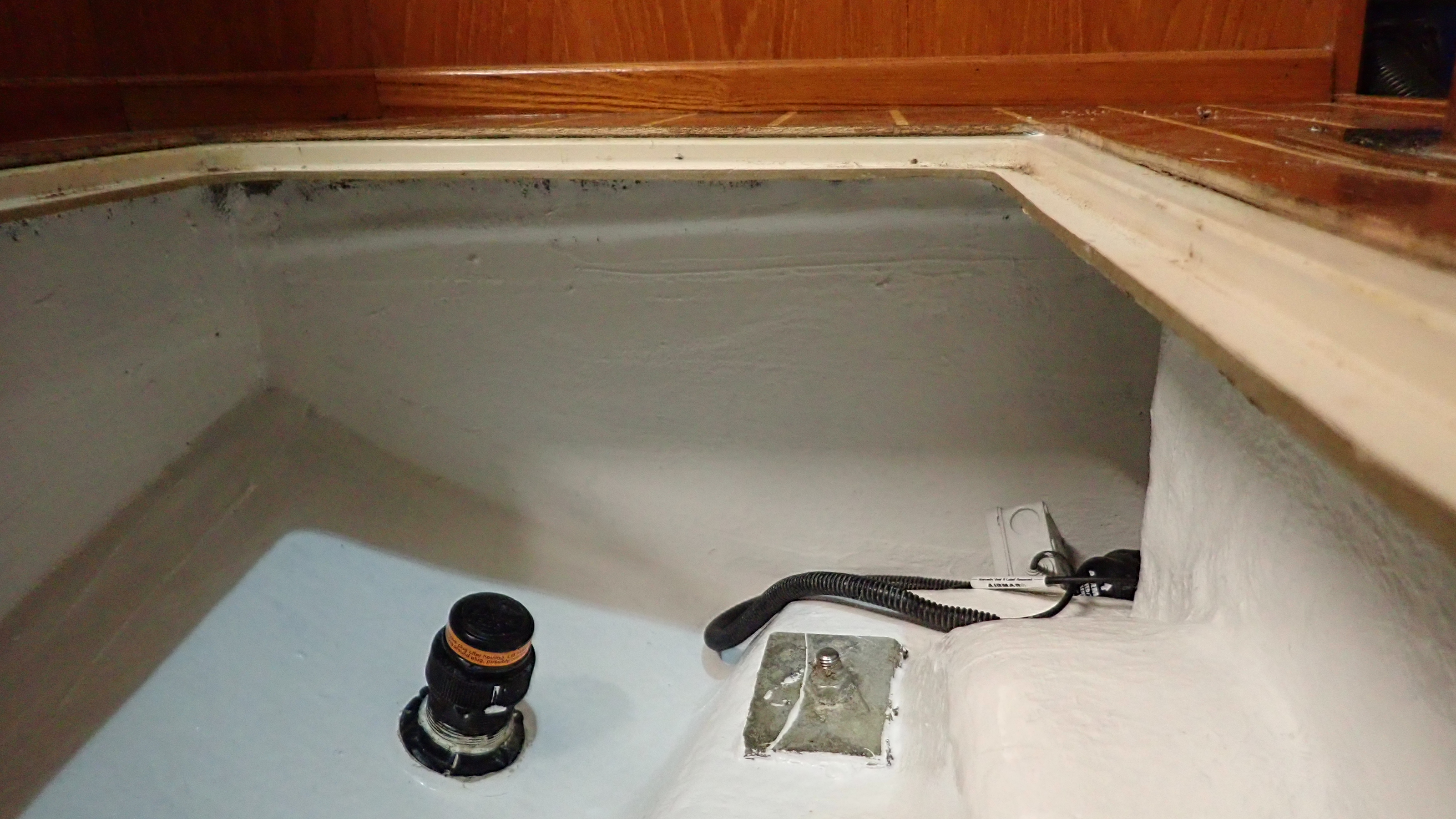
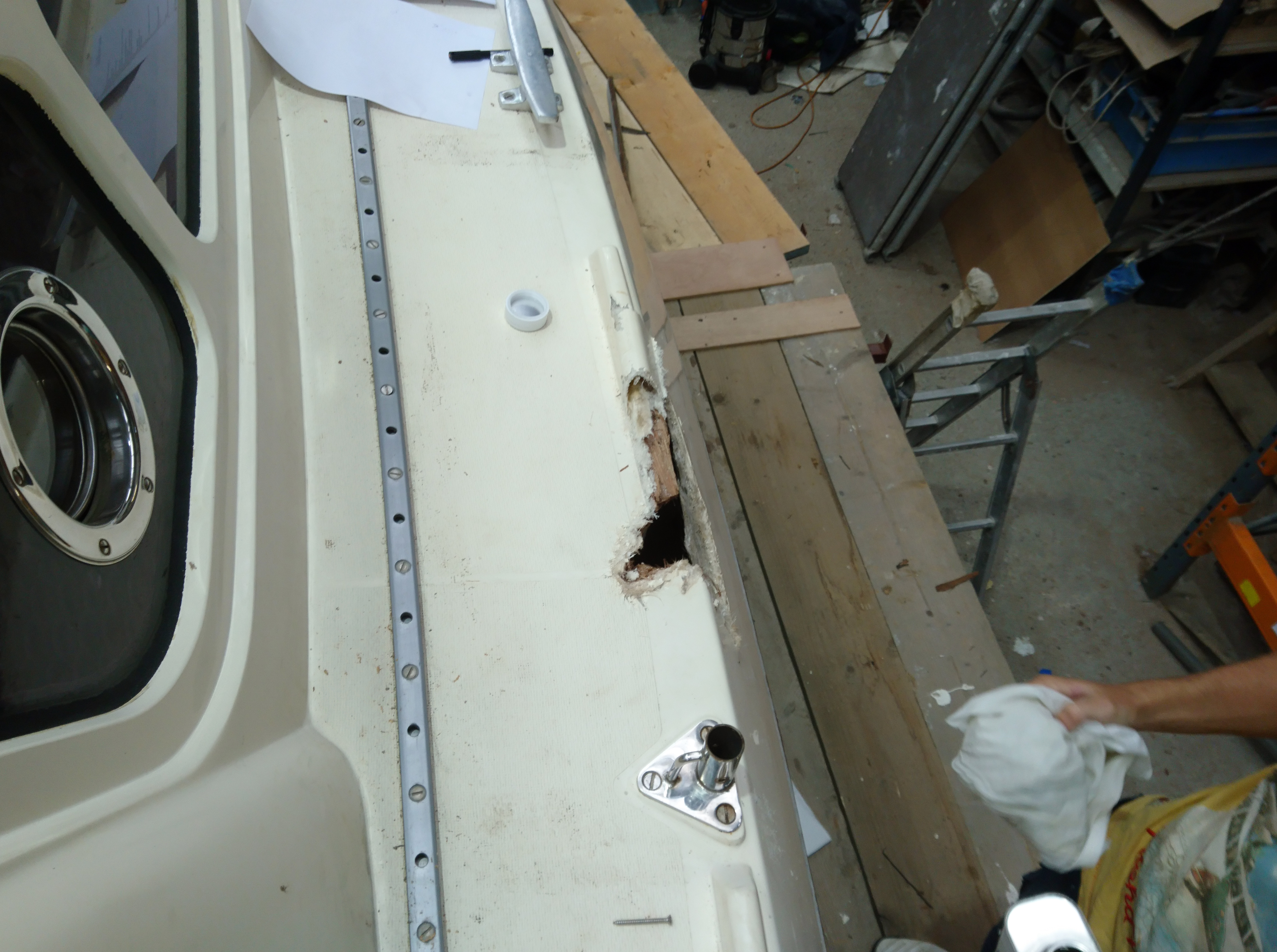
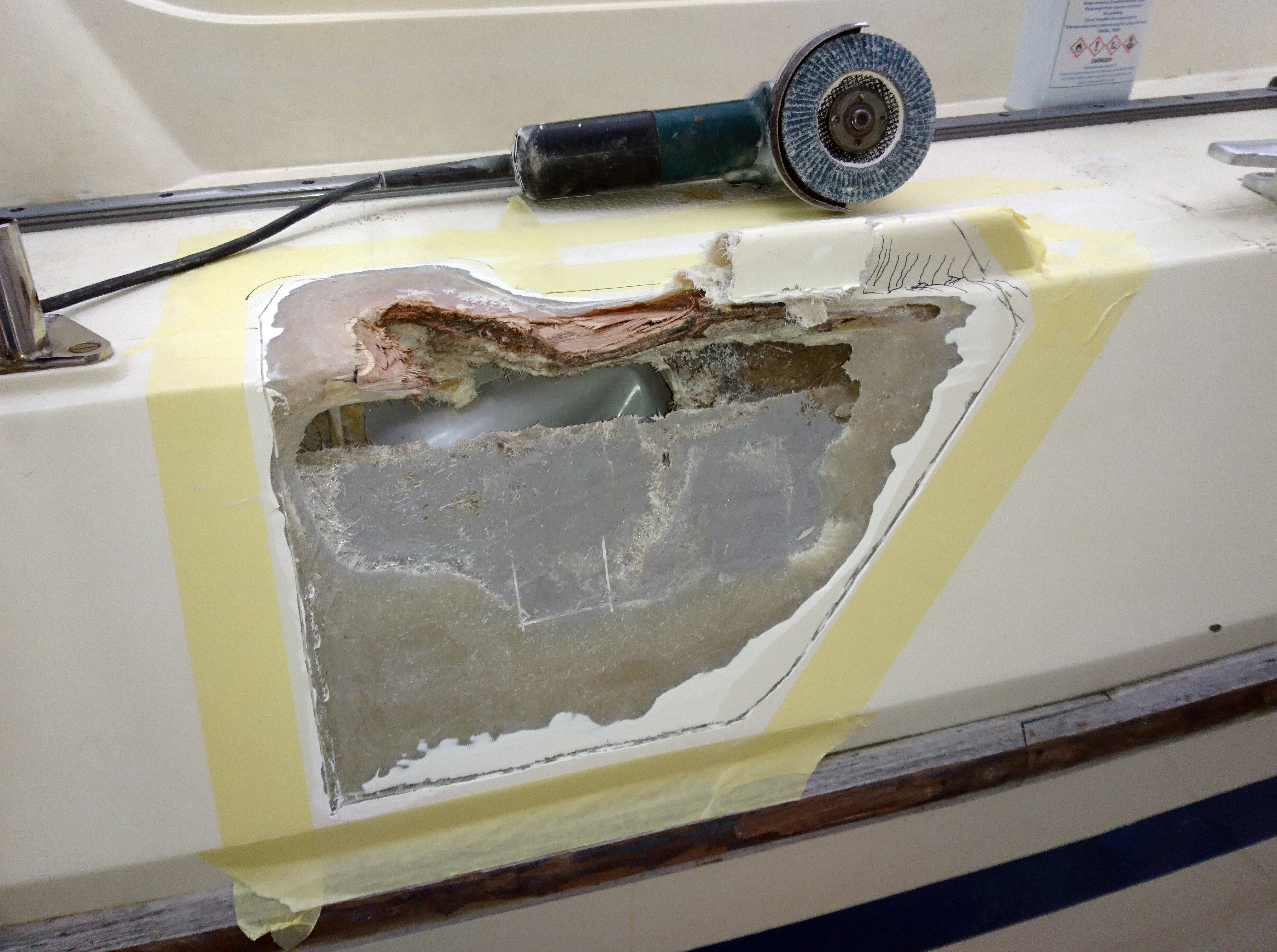
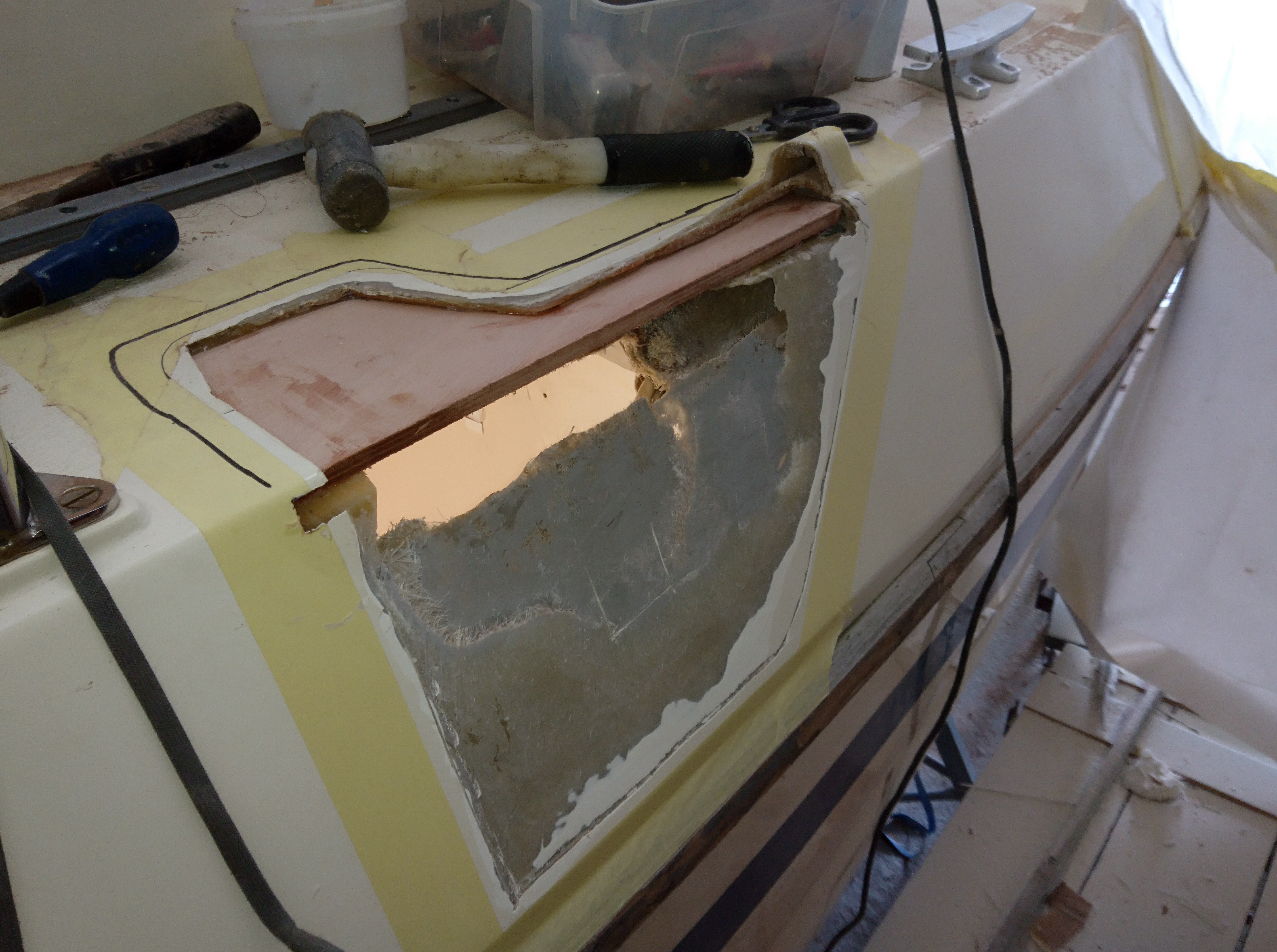
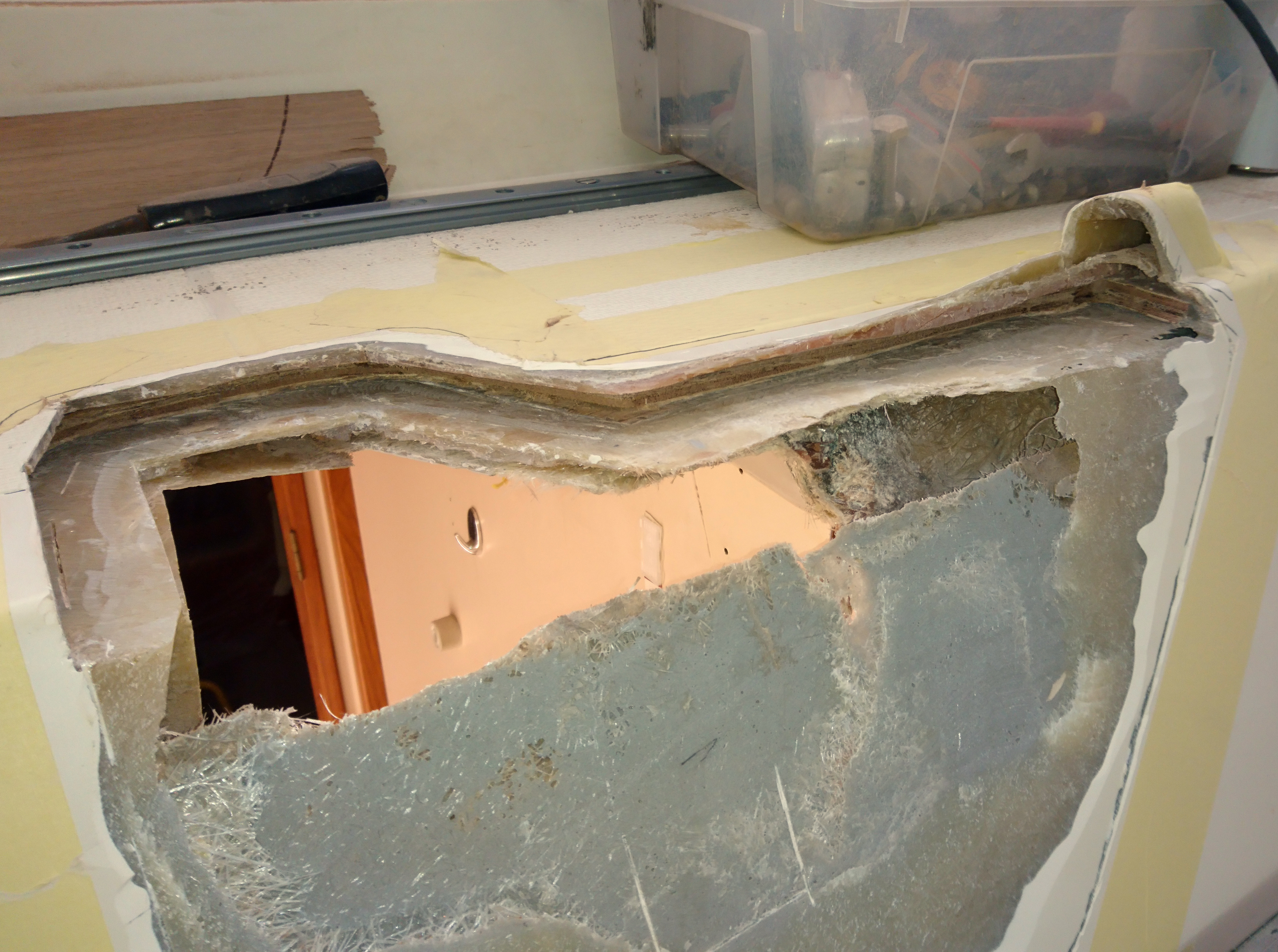
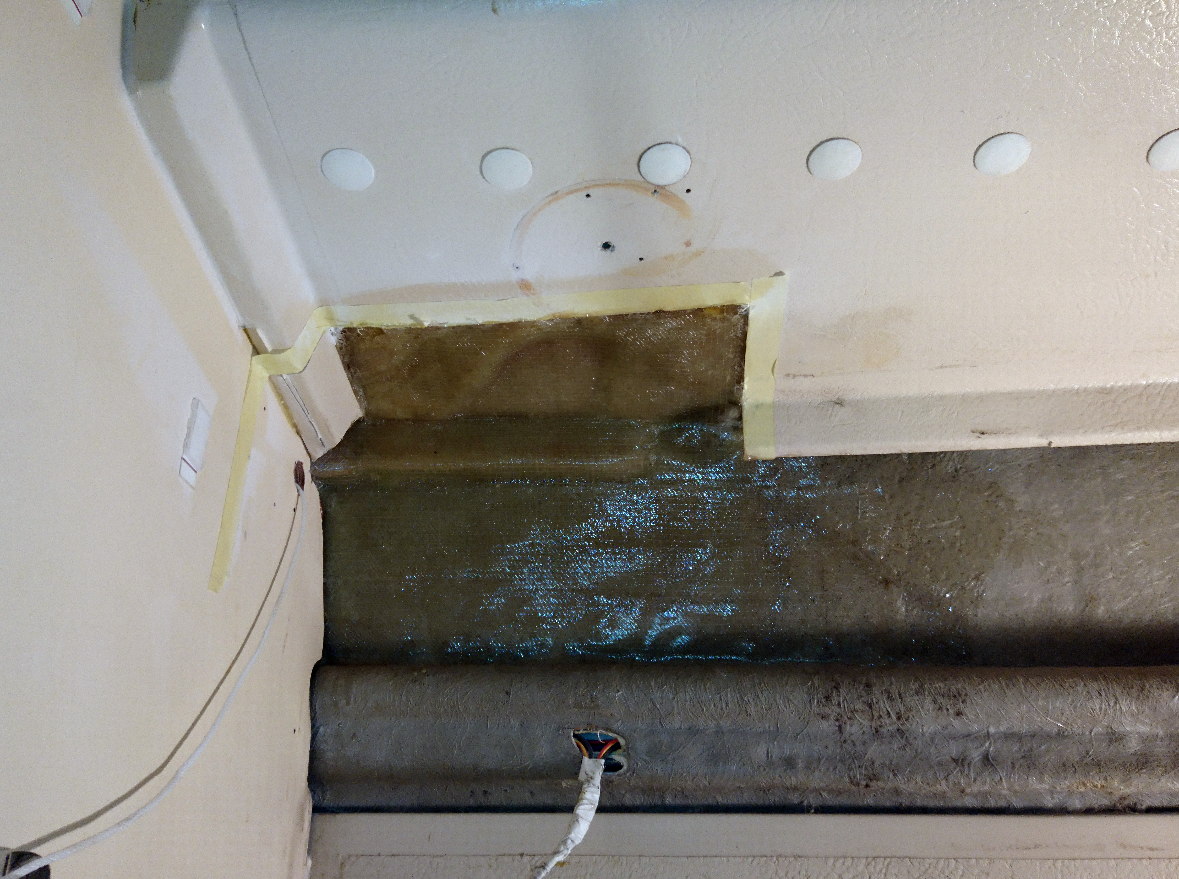
Internal access is achieved through the aft 2 holes under the double Quarter berth.
The forward big inspection hatch allows access to the rear of the engine and gearbox coupling.
The middle hatch allows acces to the stern gland and greaser.
The aft hatch allows acces to the aft of the keel and the exit of the propshaft tube.
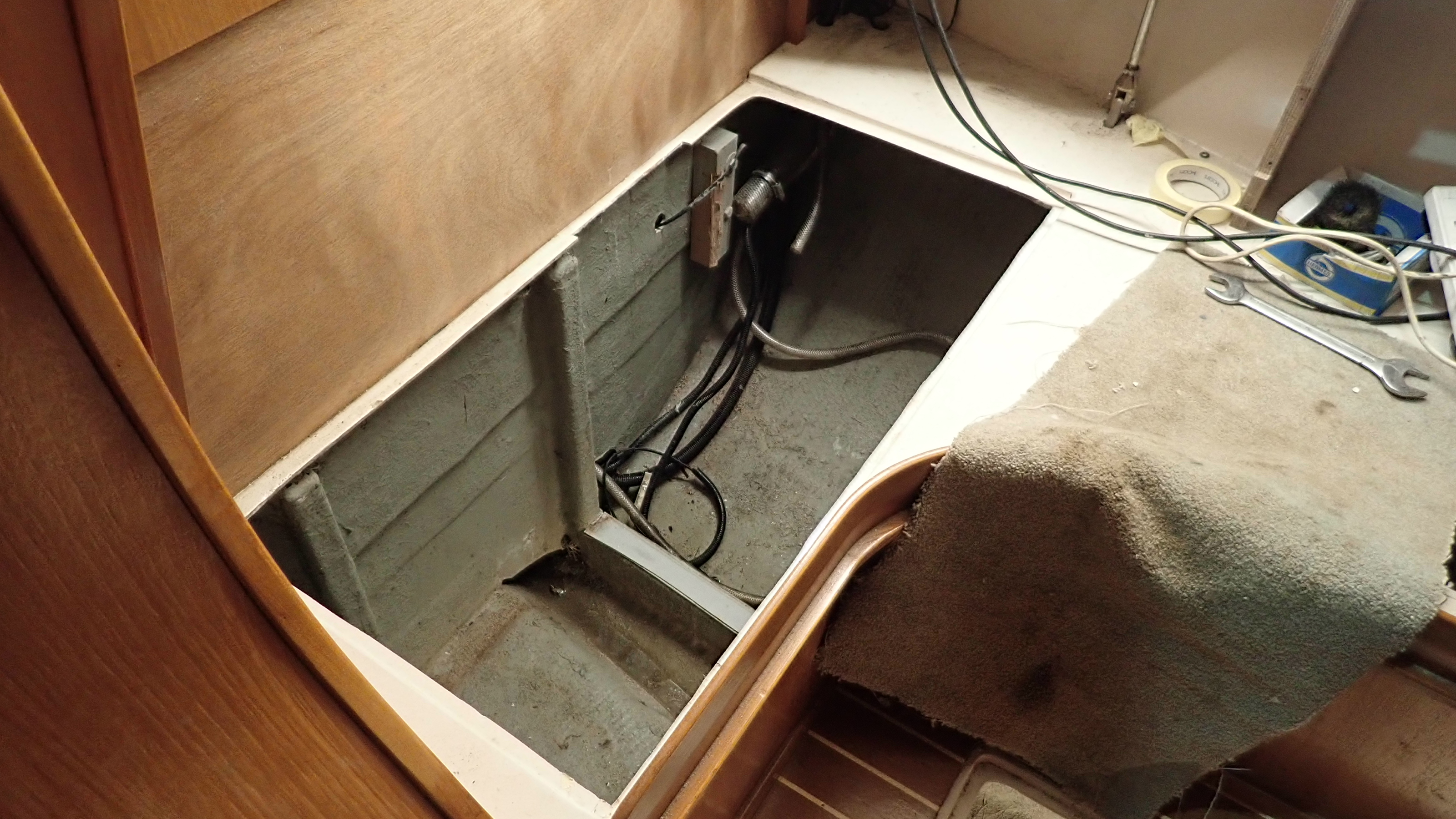
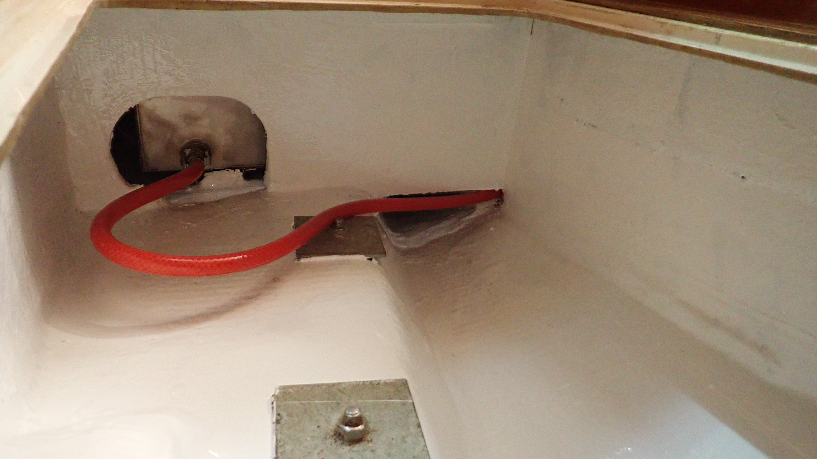
You can’t remove the propshaft from the boat aft as the rudder is in the way.
There is also no room to take it forward as you can’t get it past the engine.
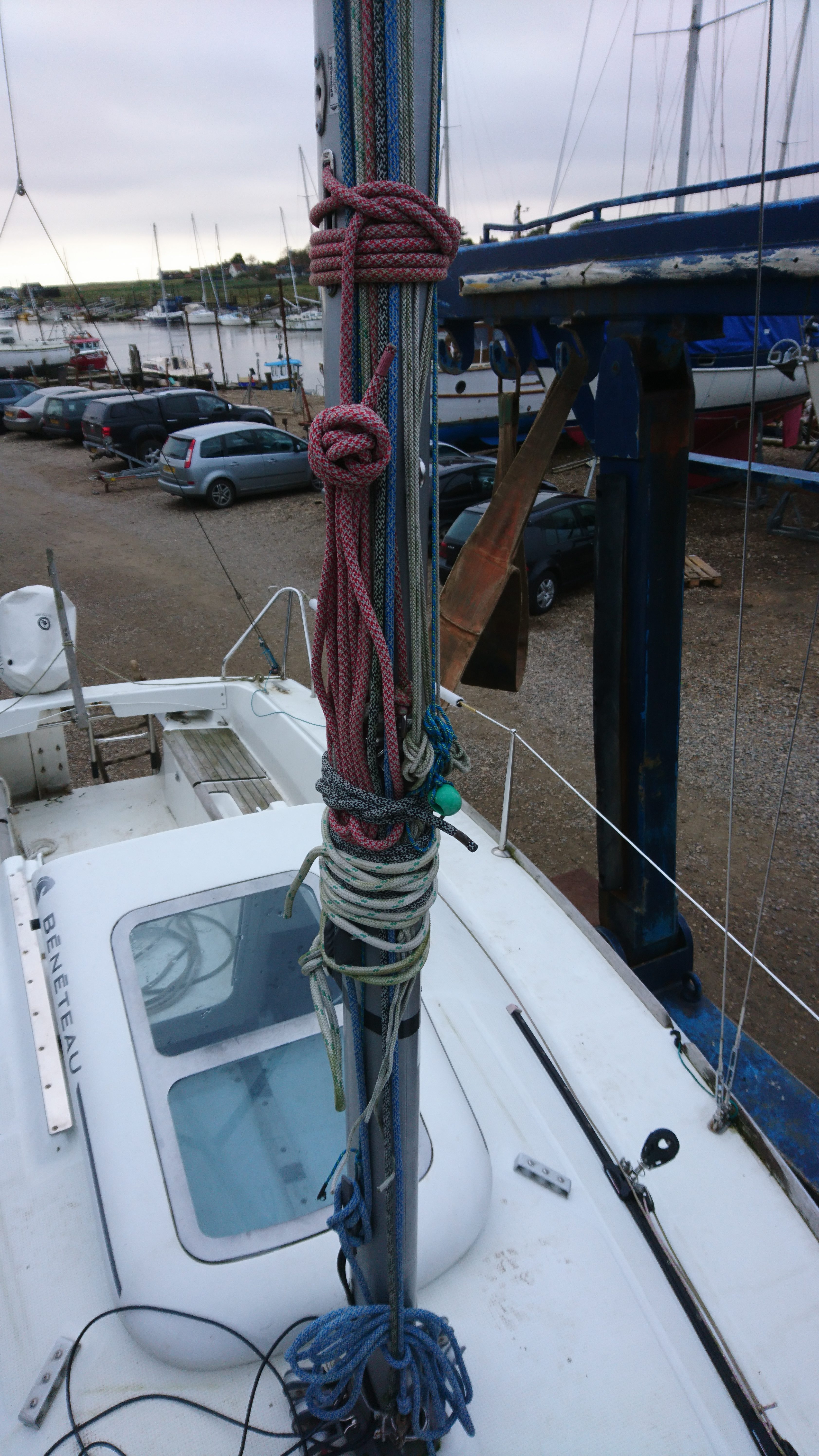
We did find that we could manoeuvre one end down into the bilge and the other end poking out of the aft hole.
The red rope is there to hold the propshaft in place whilst we effect the repairs.
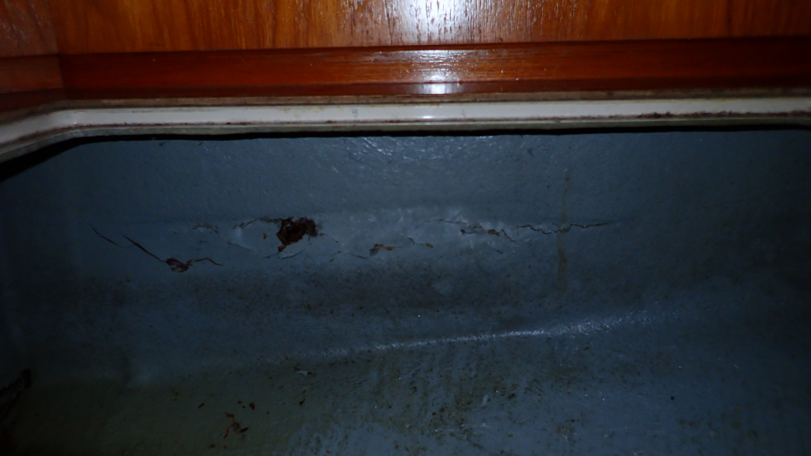
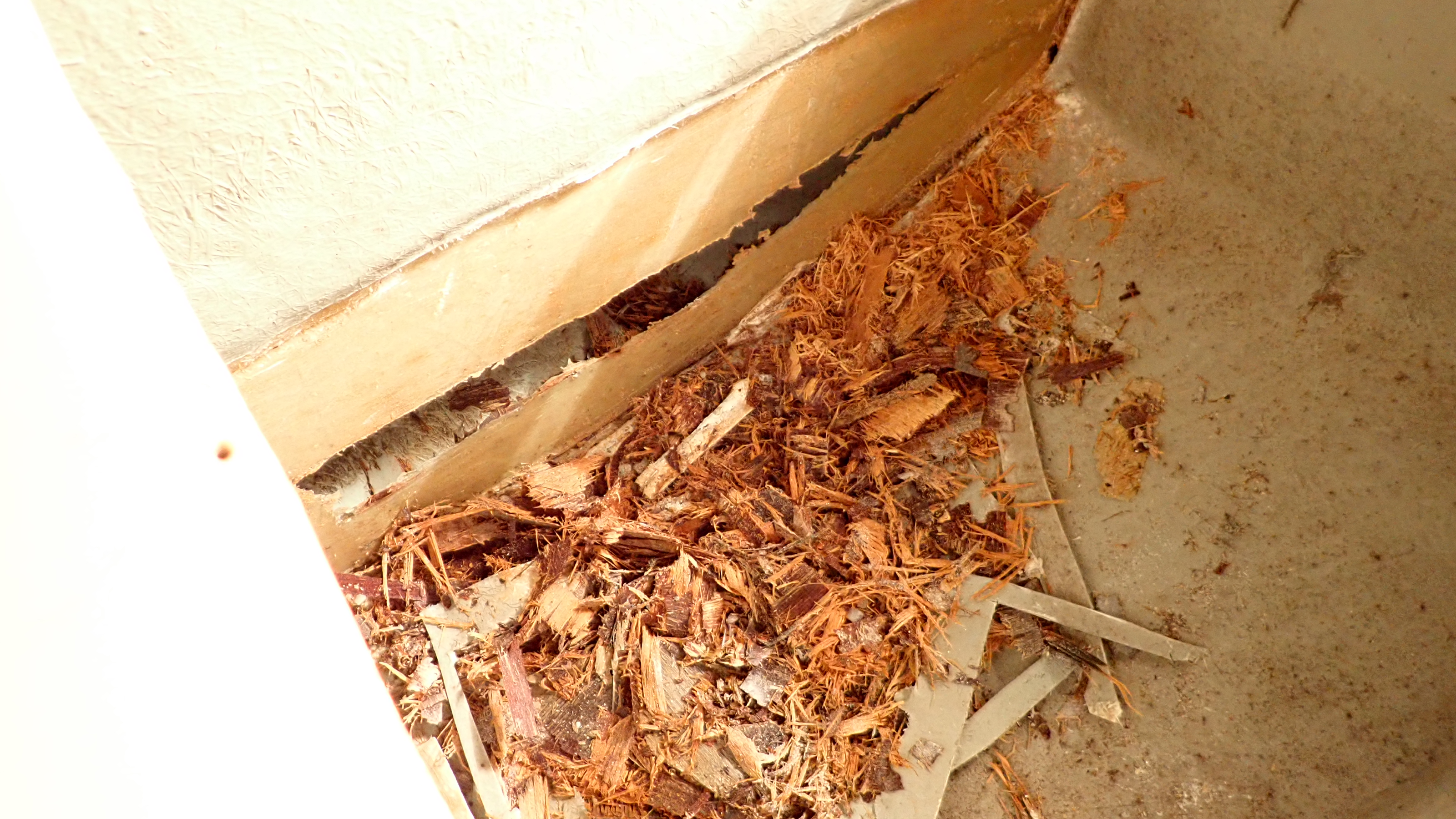
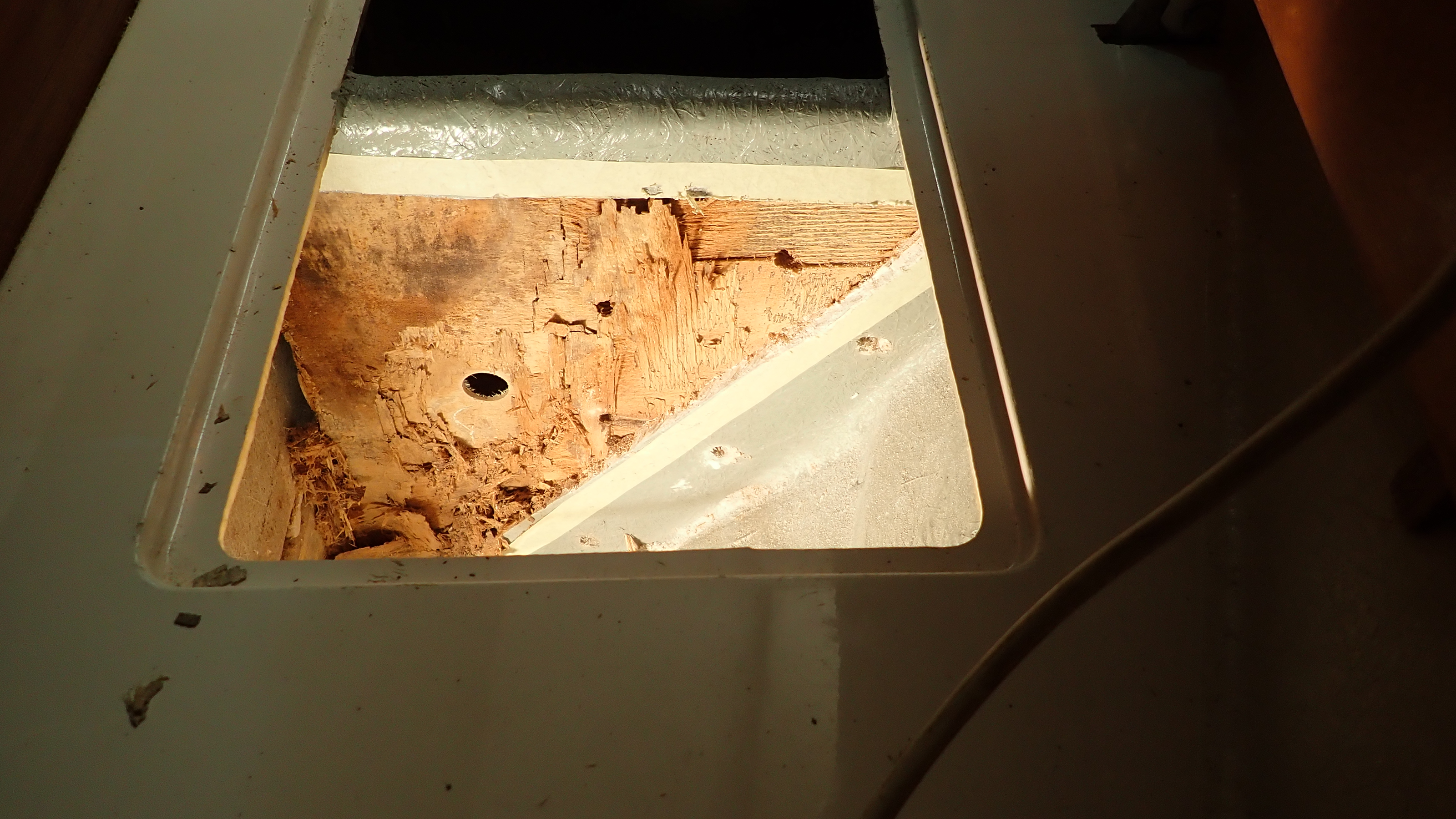
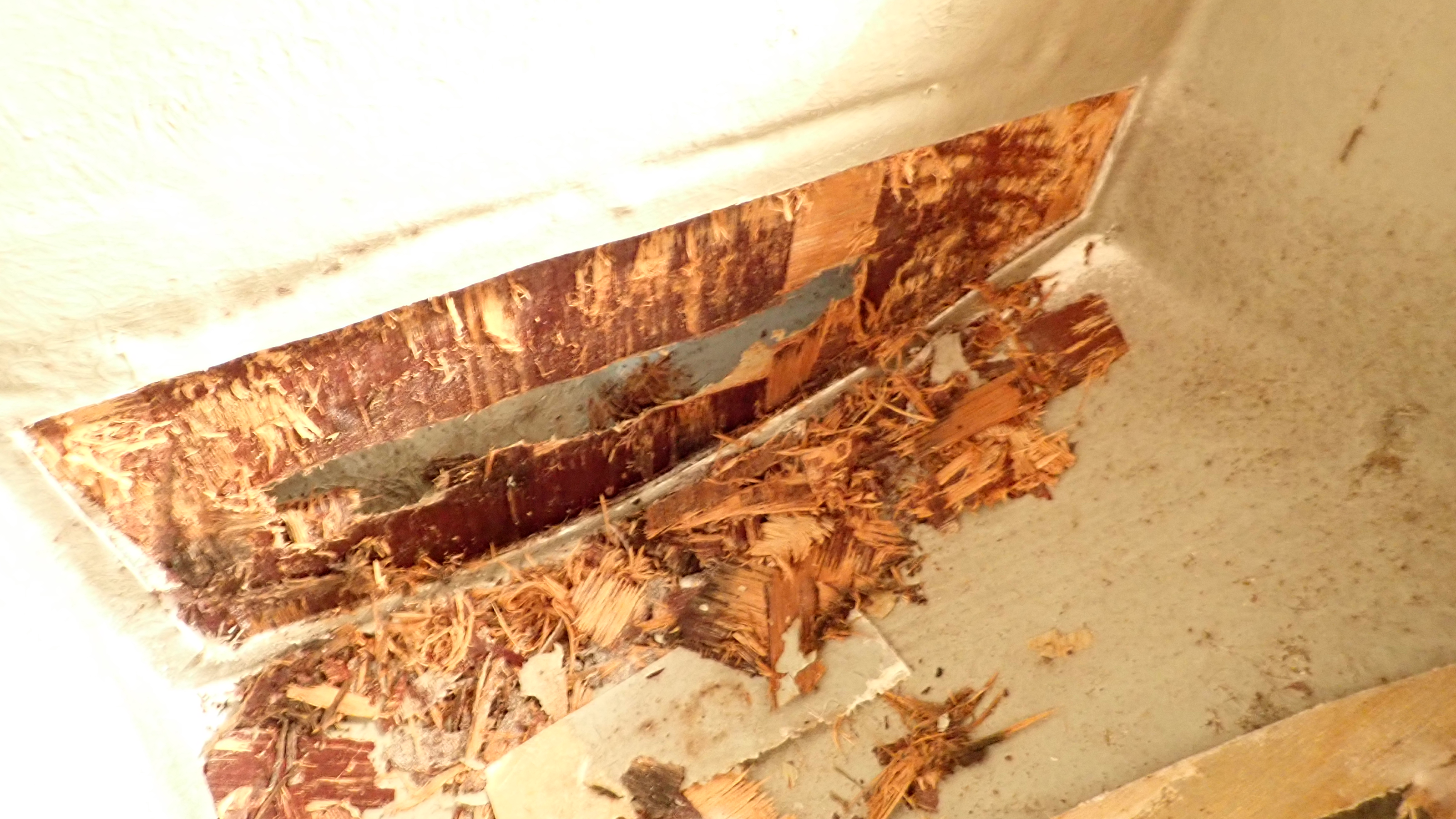
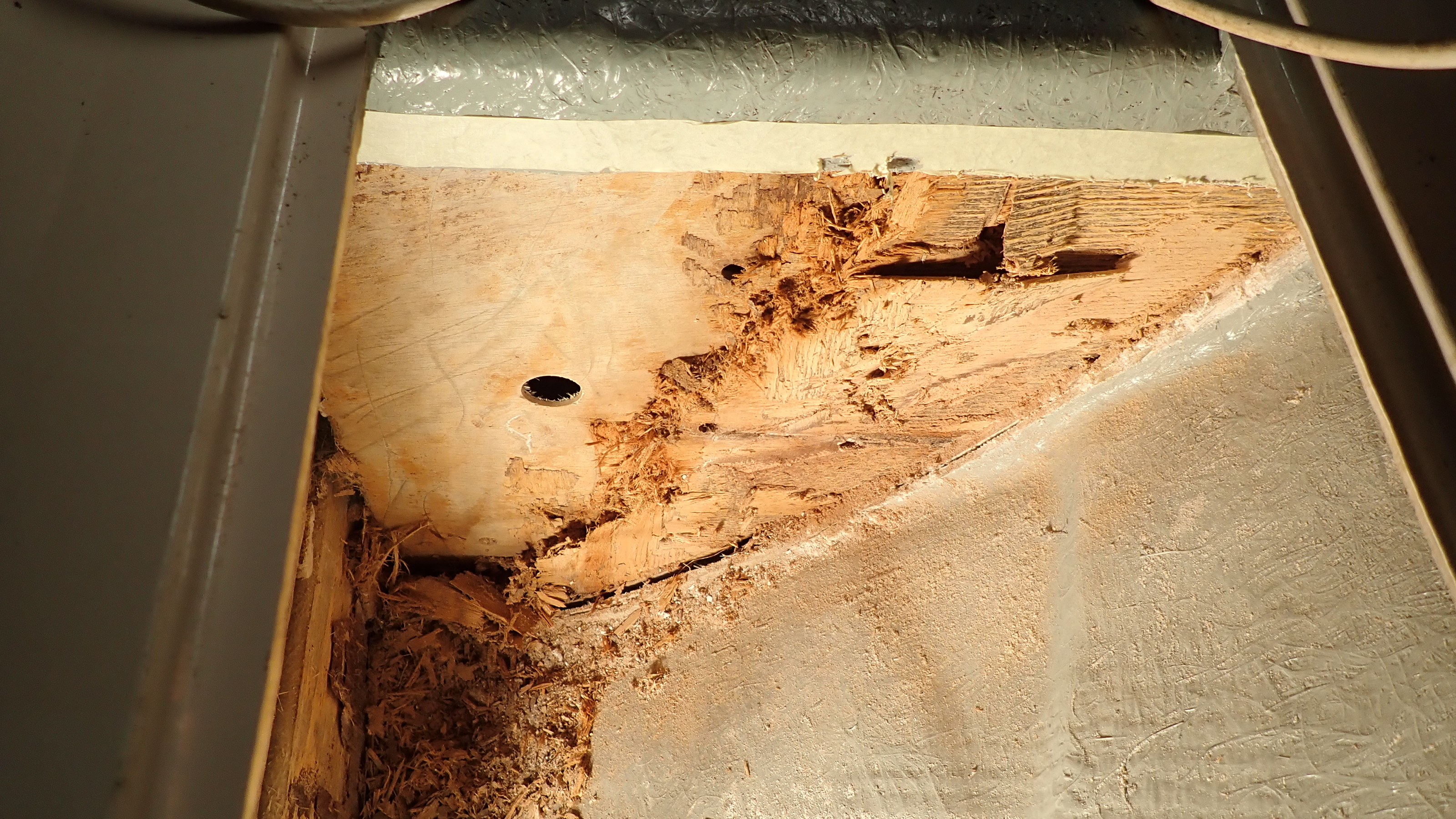
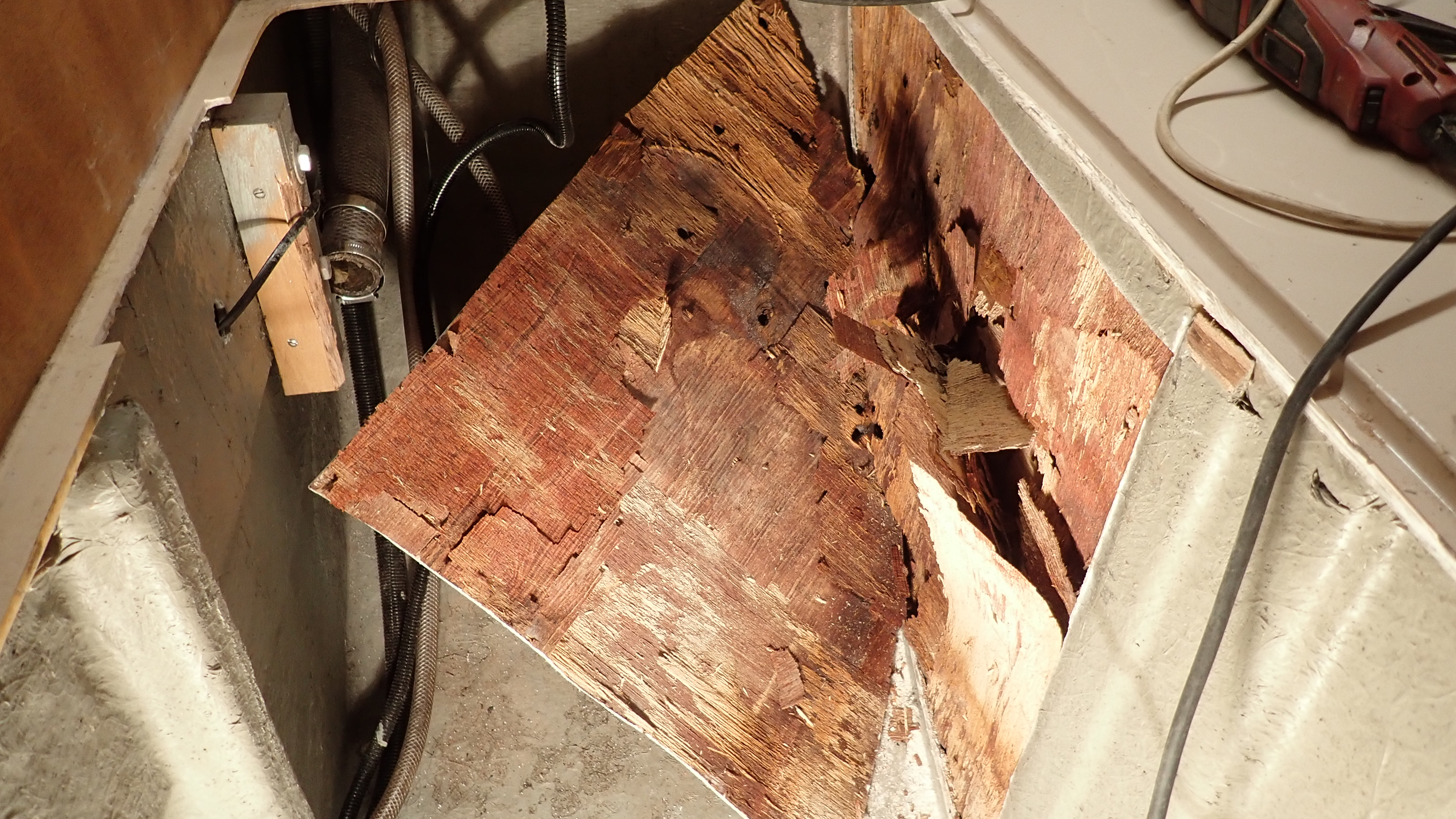
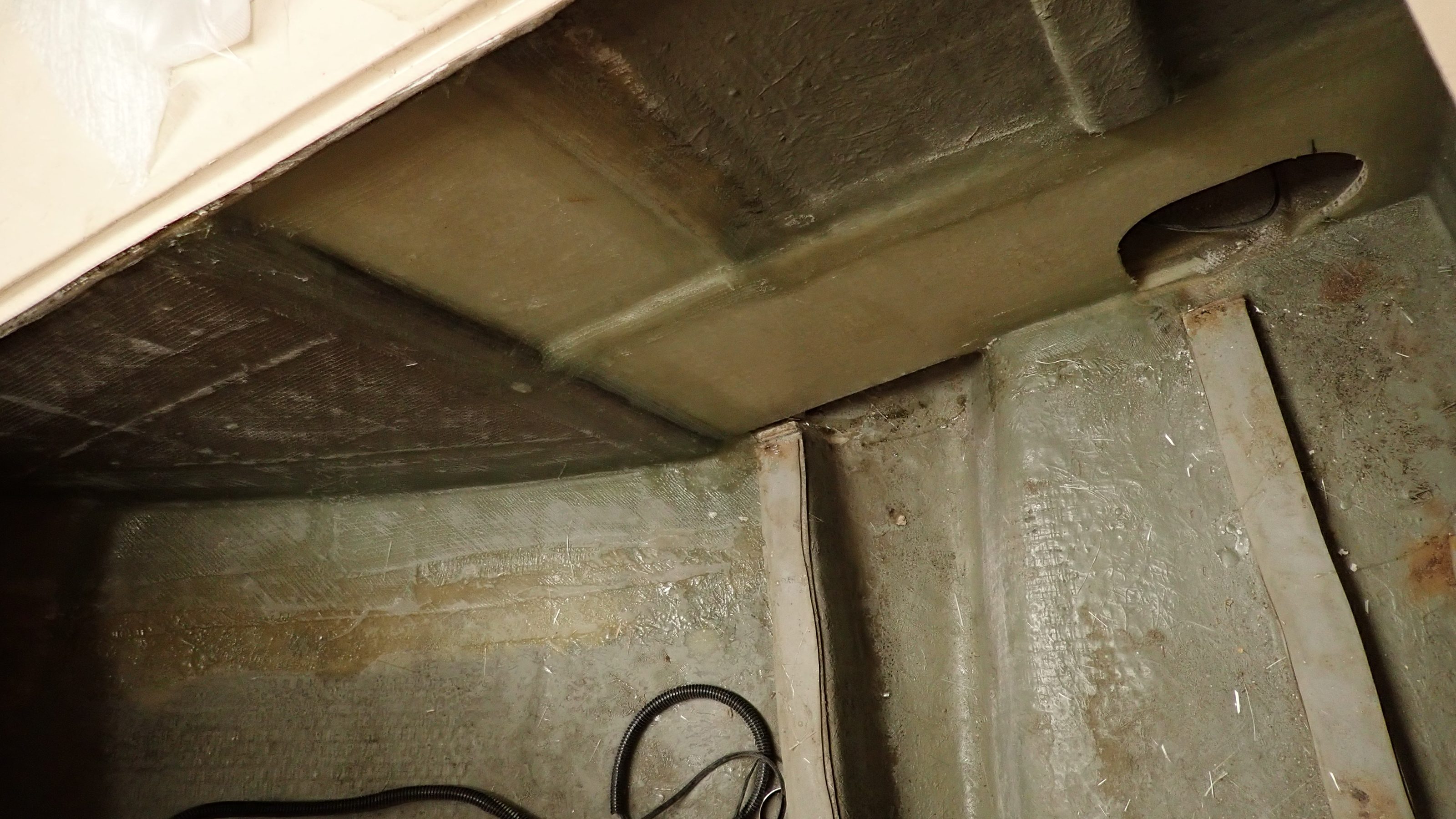
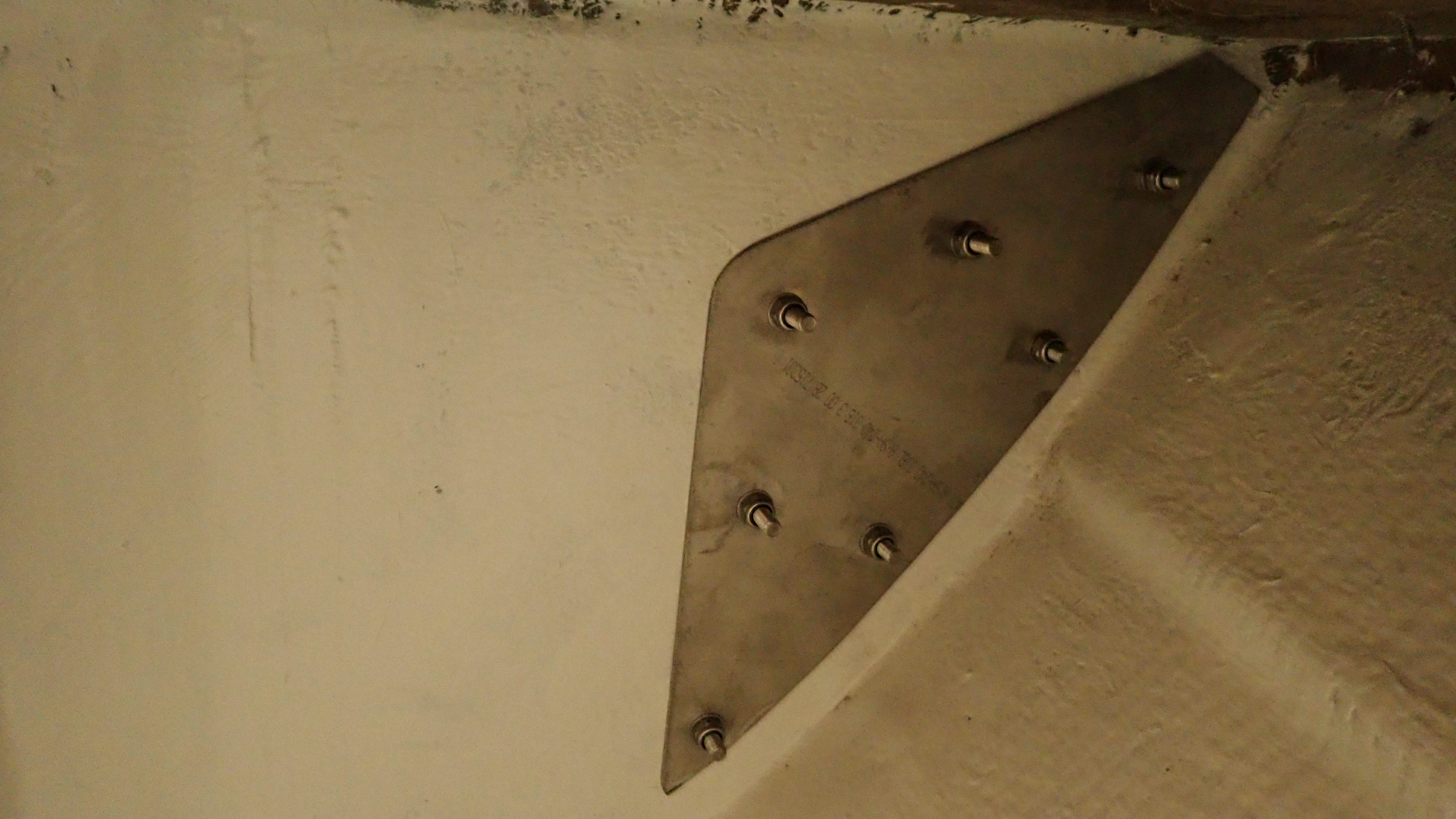
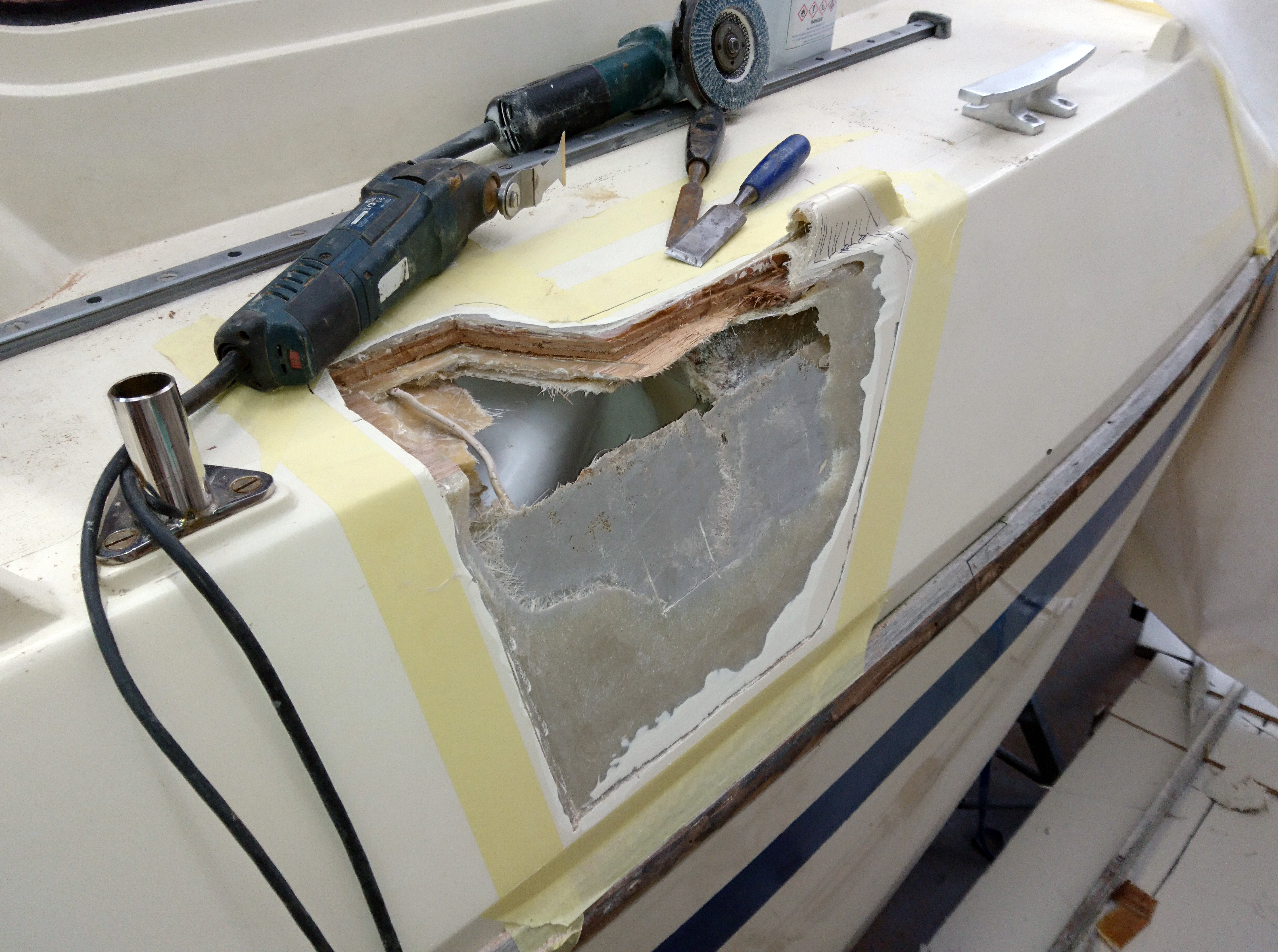
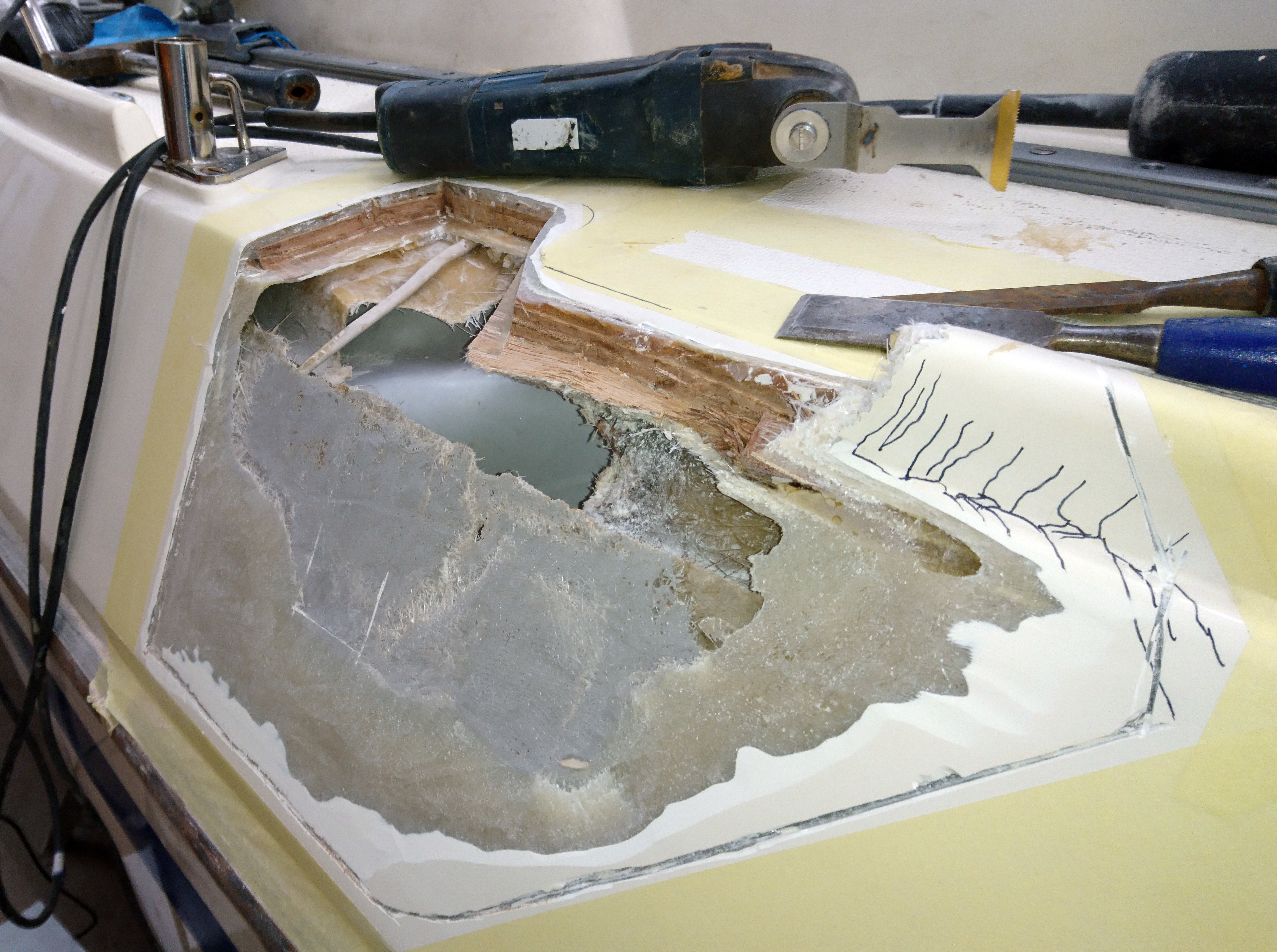
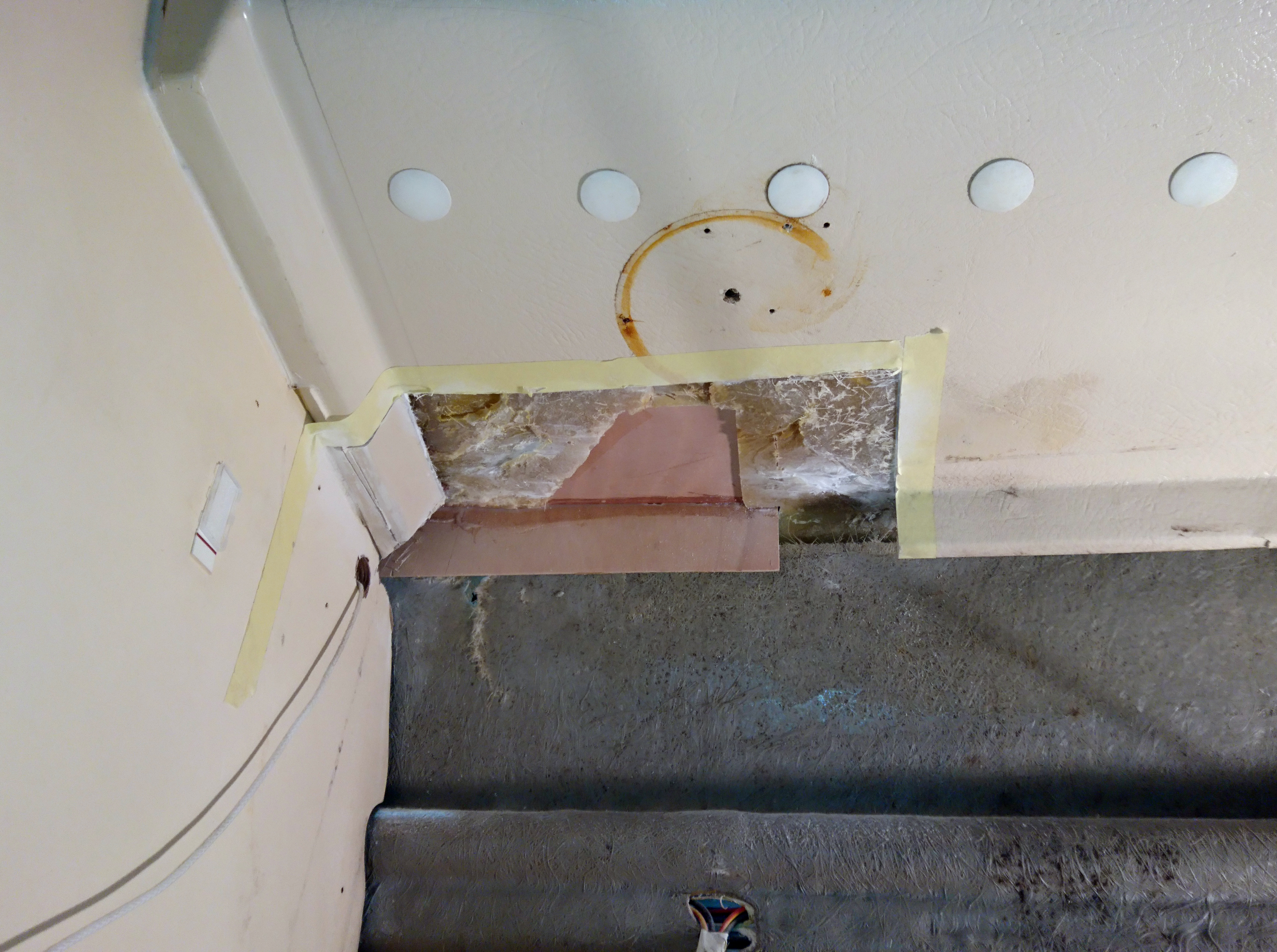
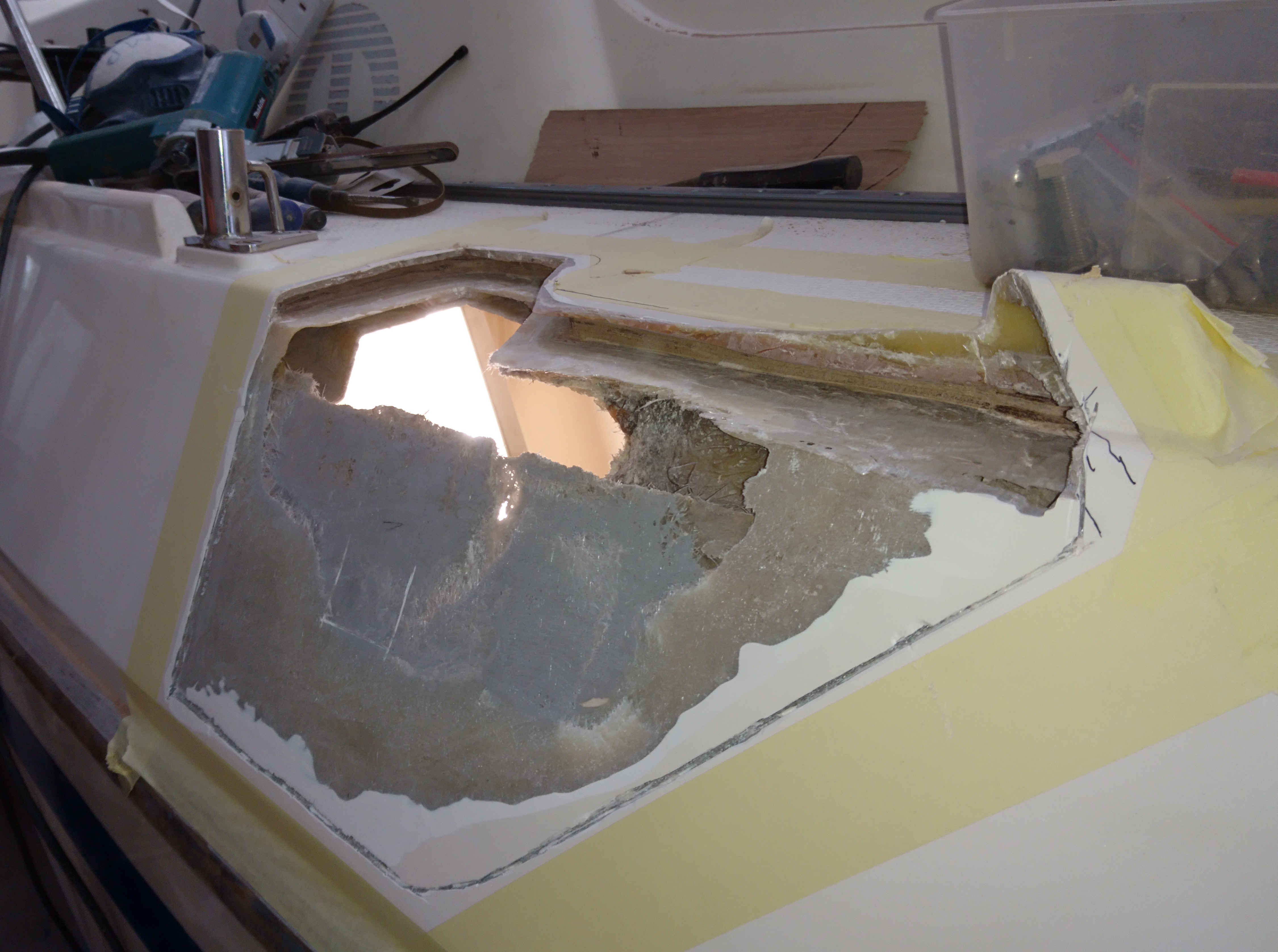
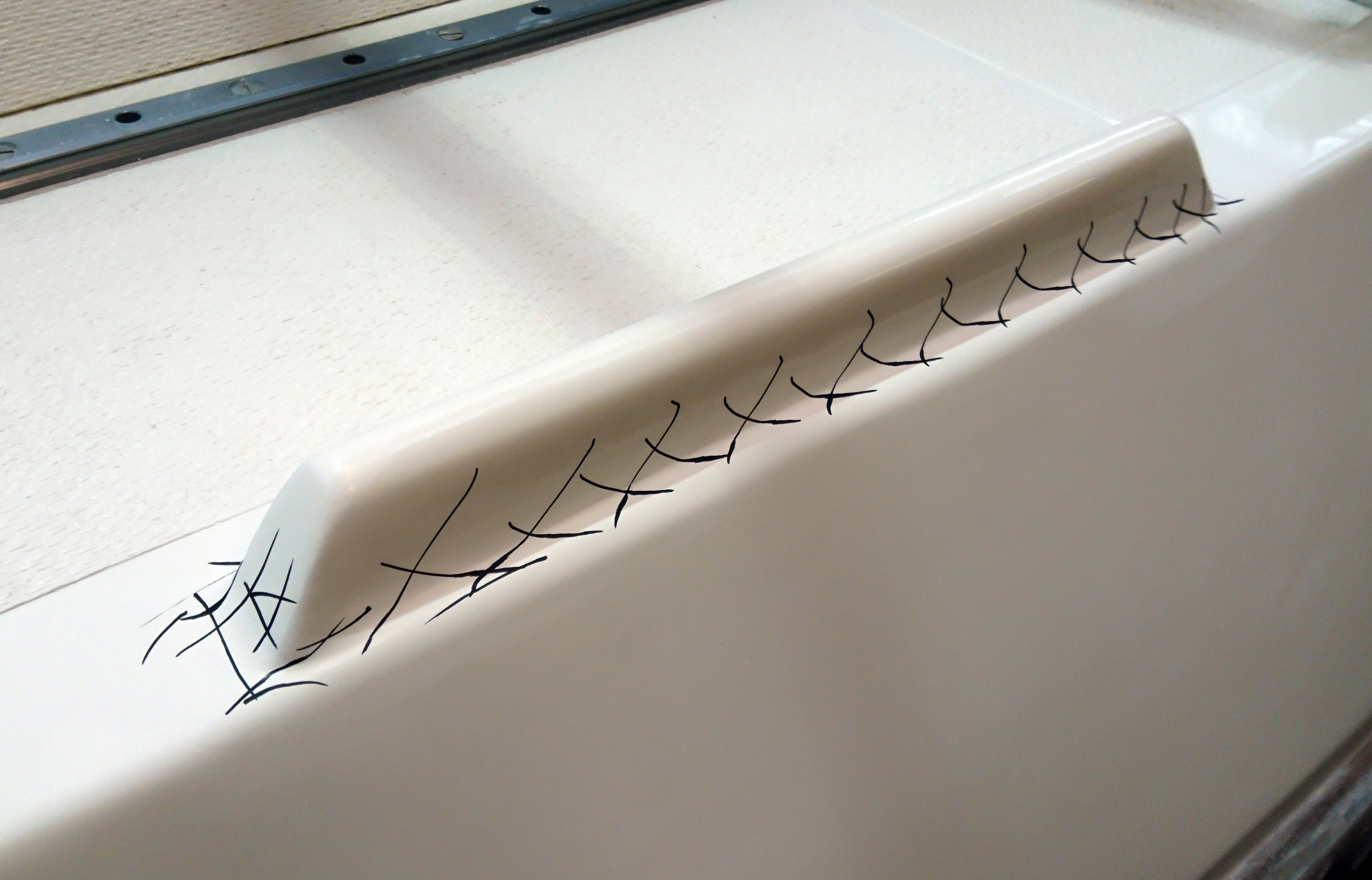
The next image was taken looking down and aft.
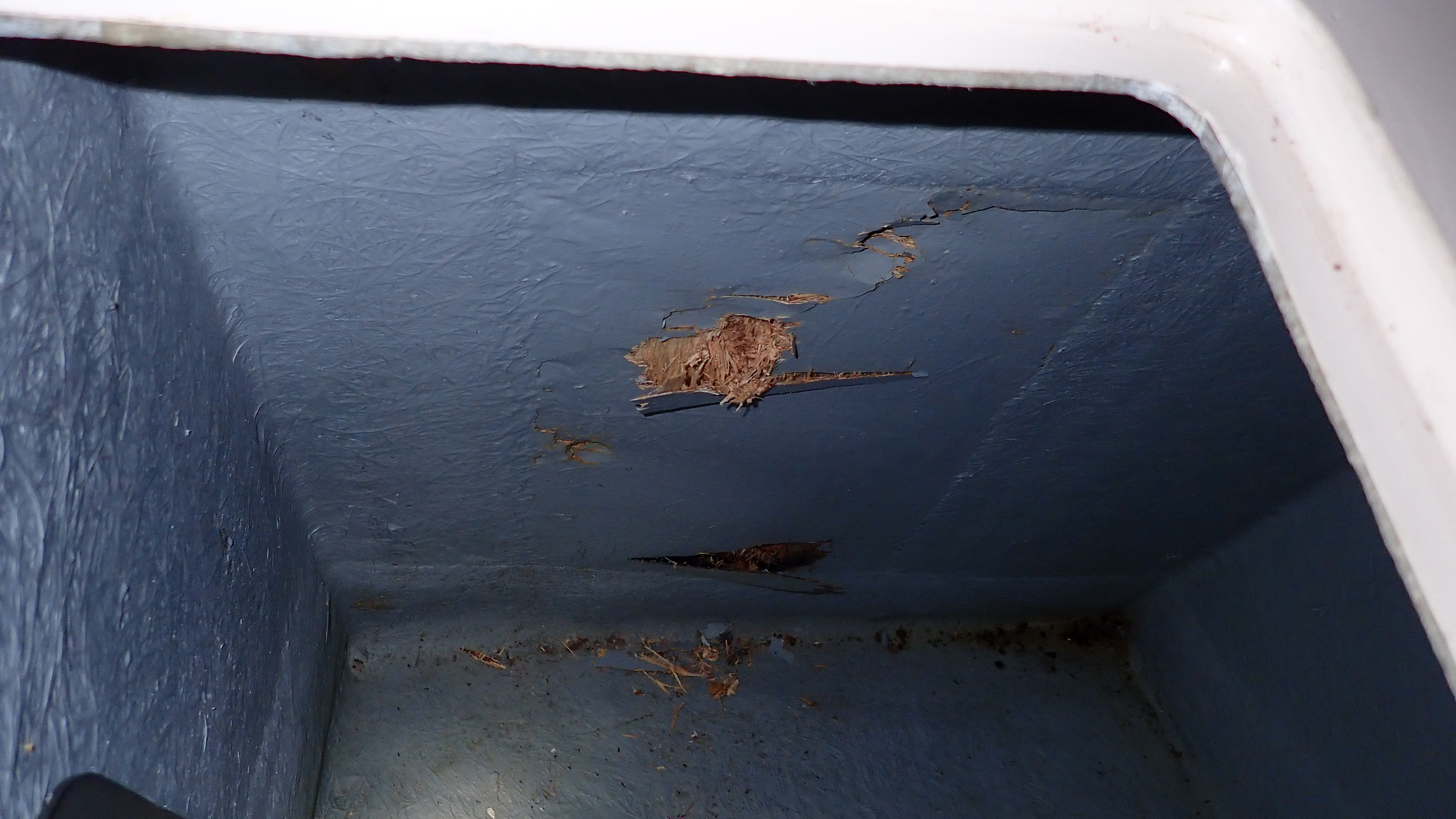
The keel is around an arms length deep and no more than 3” wide at the bottom.
You can see there is no support or even any localised strengthening around the propshaft exit hole.
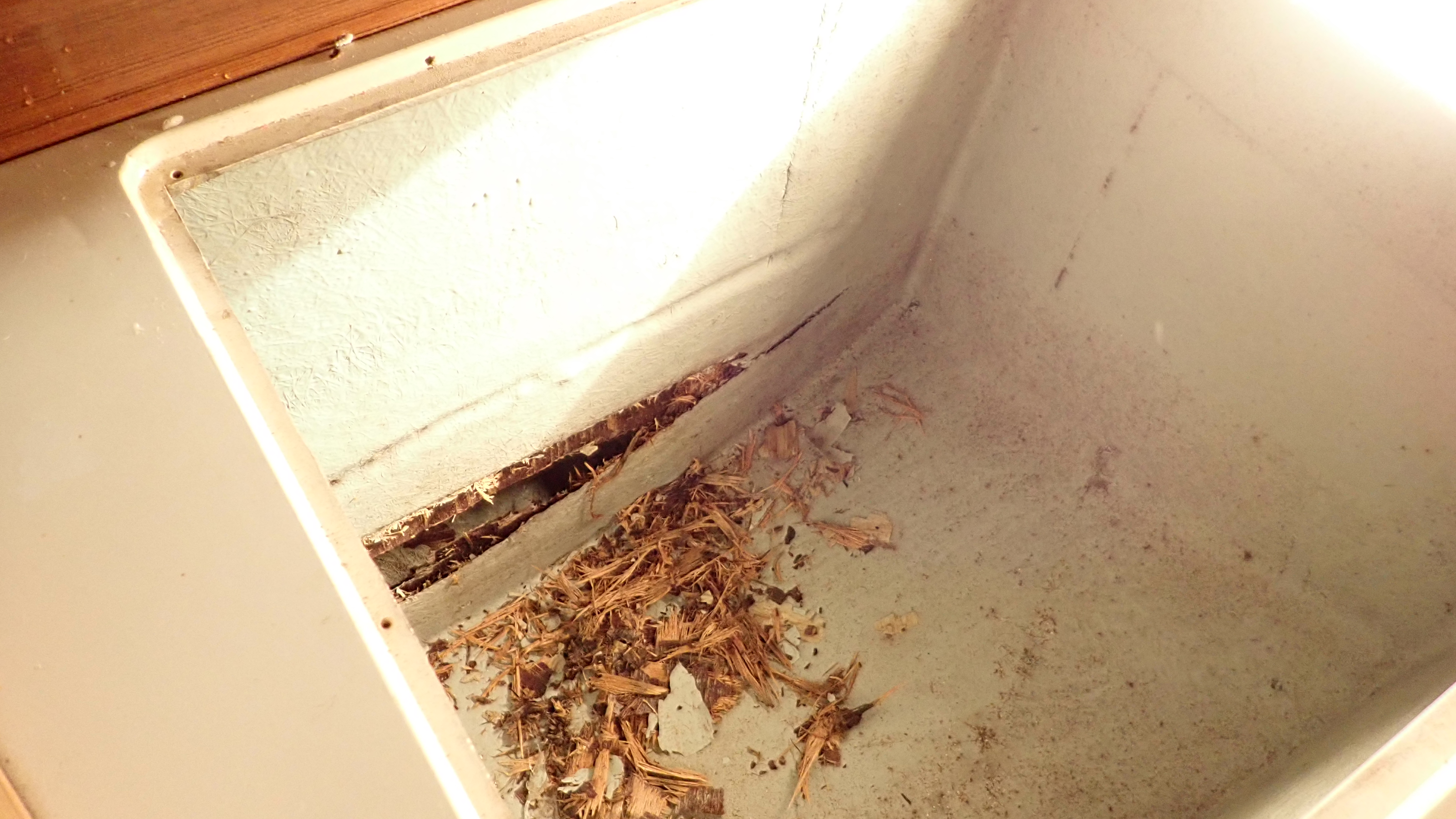
An update to now worried/relieved owner, a bit of head scratching and we arrived at a plan.
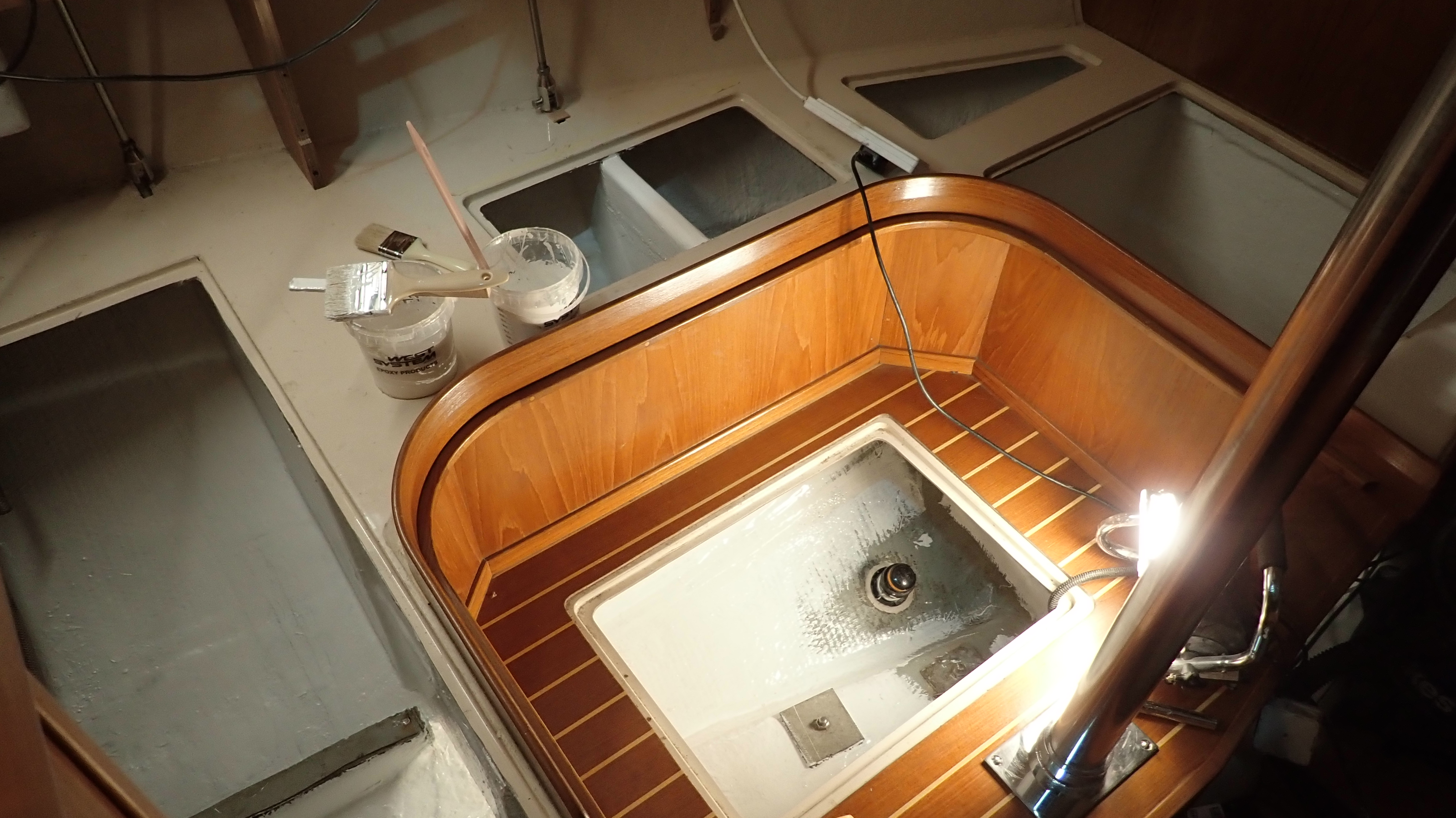
One of the first jobs was to clean all the crud and mud from at the bottom of the keel, now where did that apprentice go…..


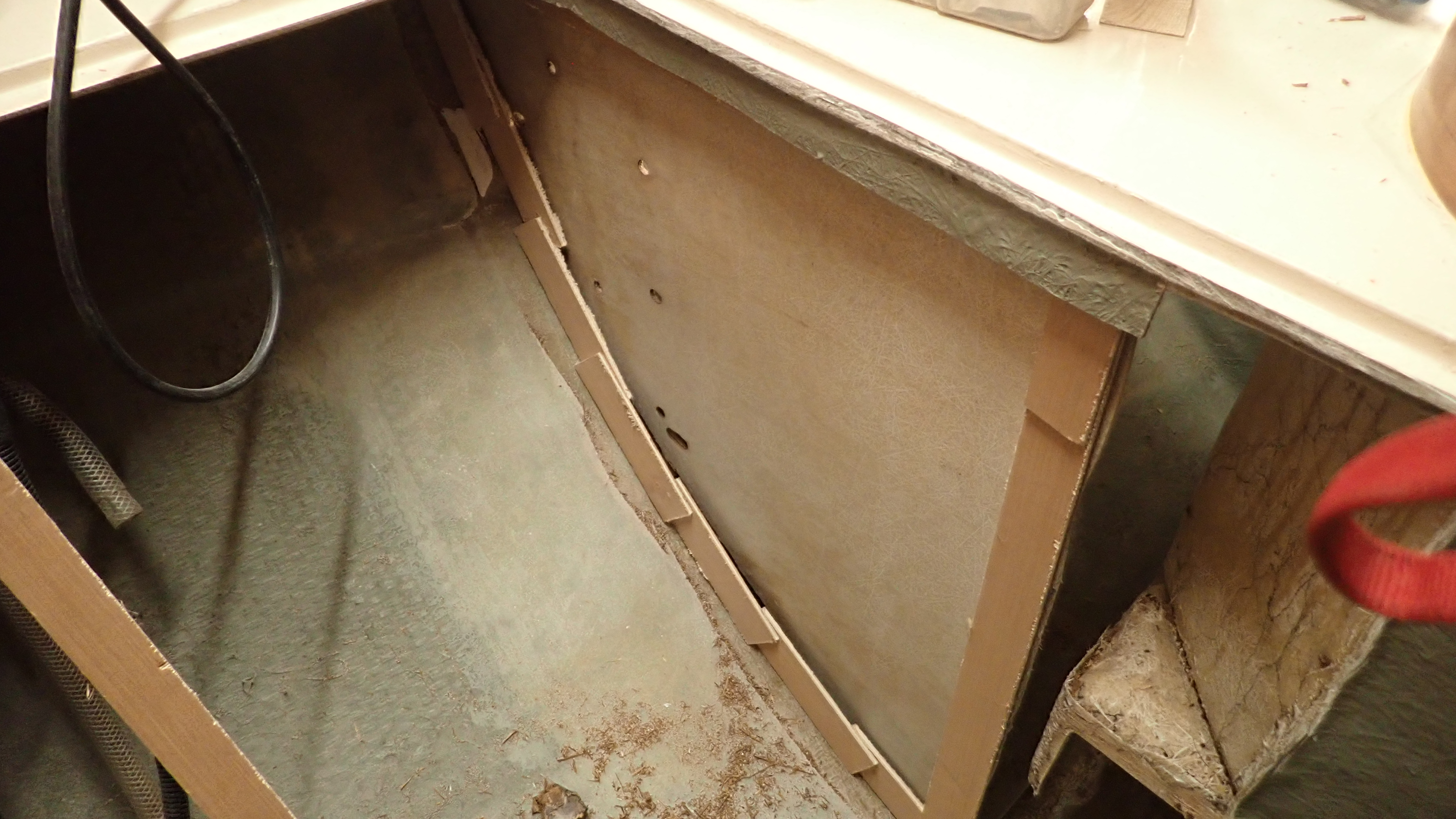
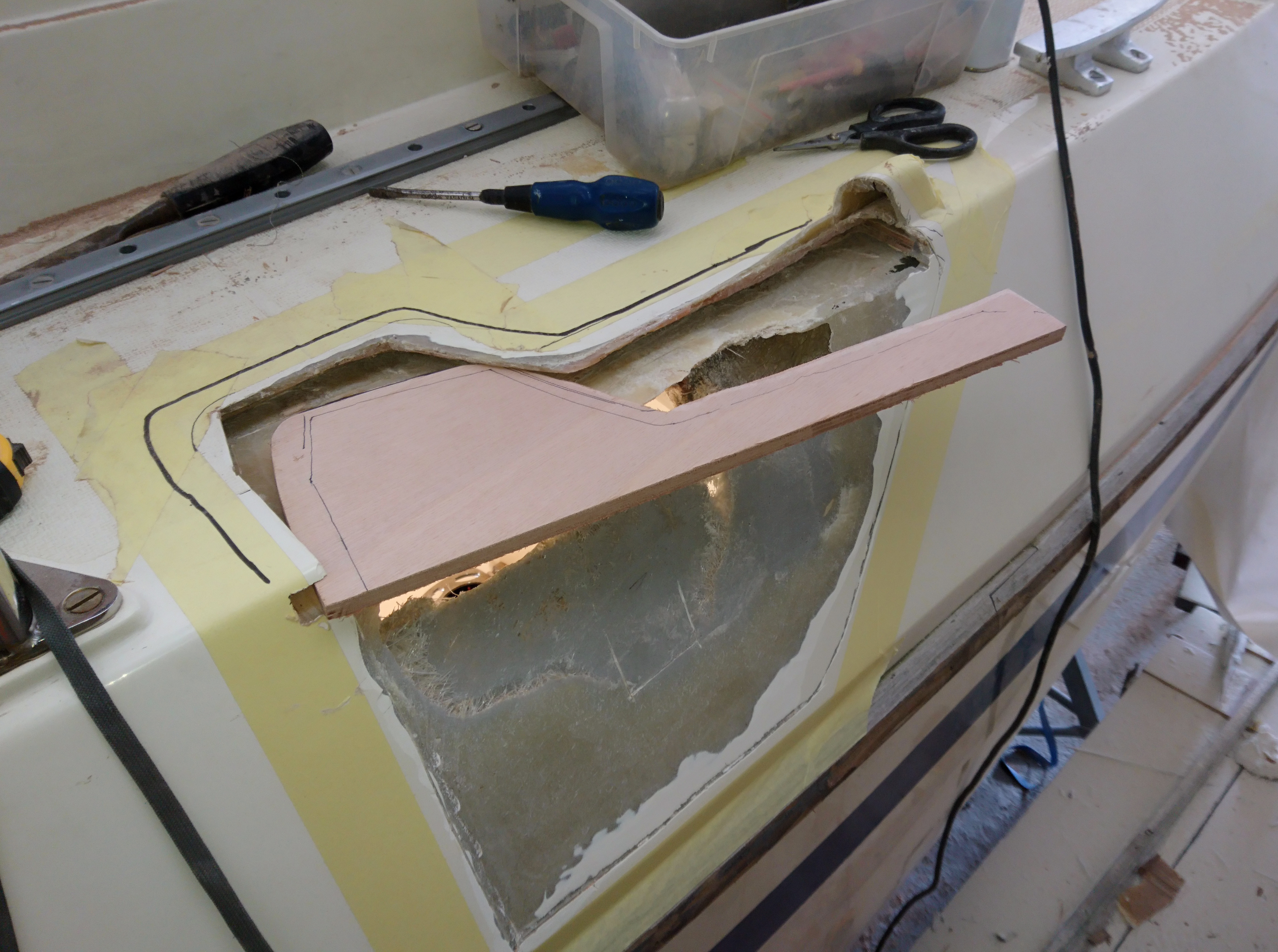
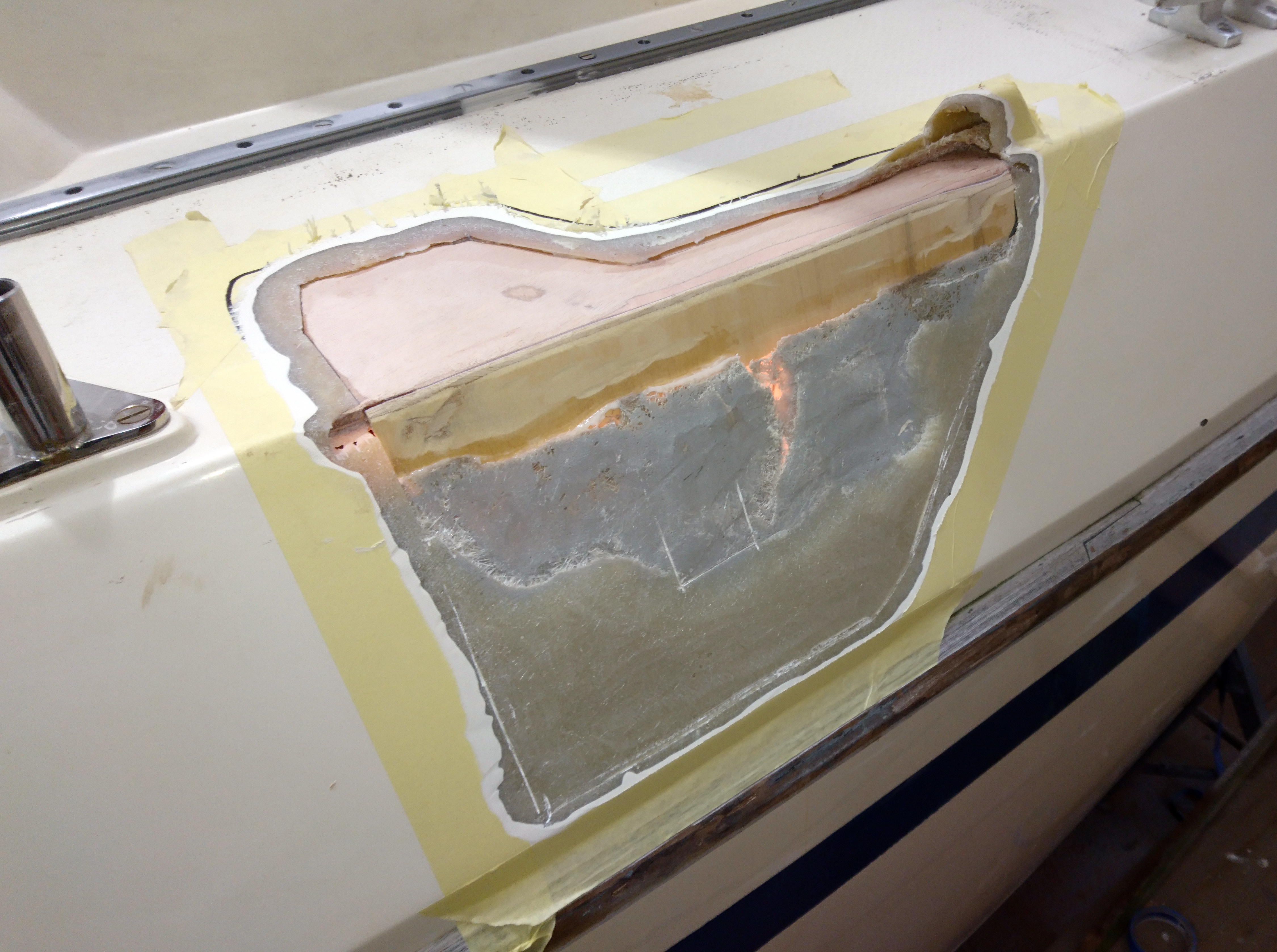
I decided to make a dam at the back of the keel up to 10mm below the exit hole and around 200mm forward.
Obviously this will live in the bilge so whatever we put down there would need not to rot, so plywood was ruled out.
Even sheathed ply will rot given the slightest hole in the sheathing.
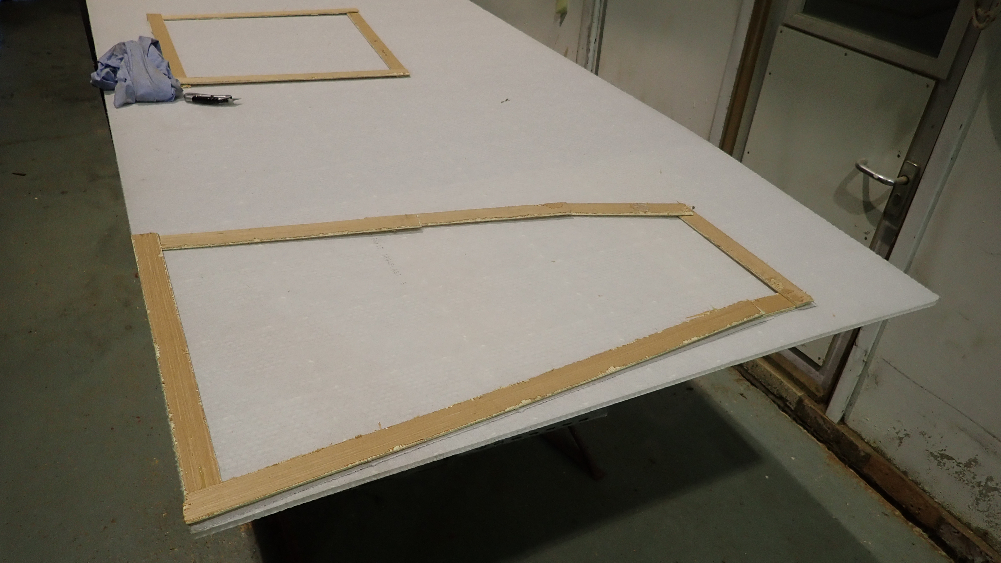
So I used my favourite core material.
Nidaplast is a plastic honeycomb with a bonded scrim on each side.
It comes in various thicknesses from 5mm to 90mm.
I mainly use 10mm or 15mm as this tends to be the same thickness used for the balsa core in decks.
A couple of layers of 250g woven cloth glassed on each side results in a panel as stiff as plywood at around ¼ of the weight,
with of course the added benefit that it wont rot.
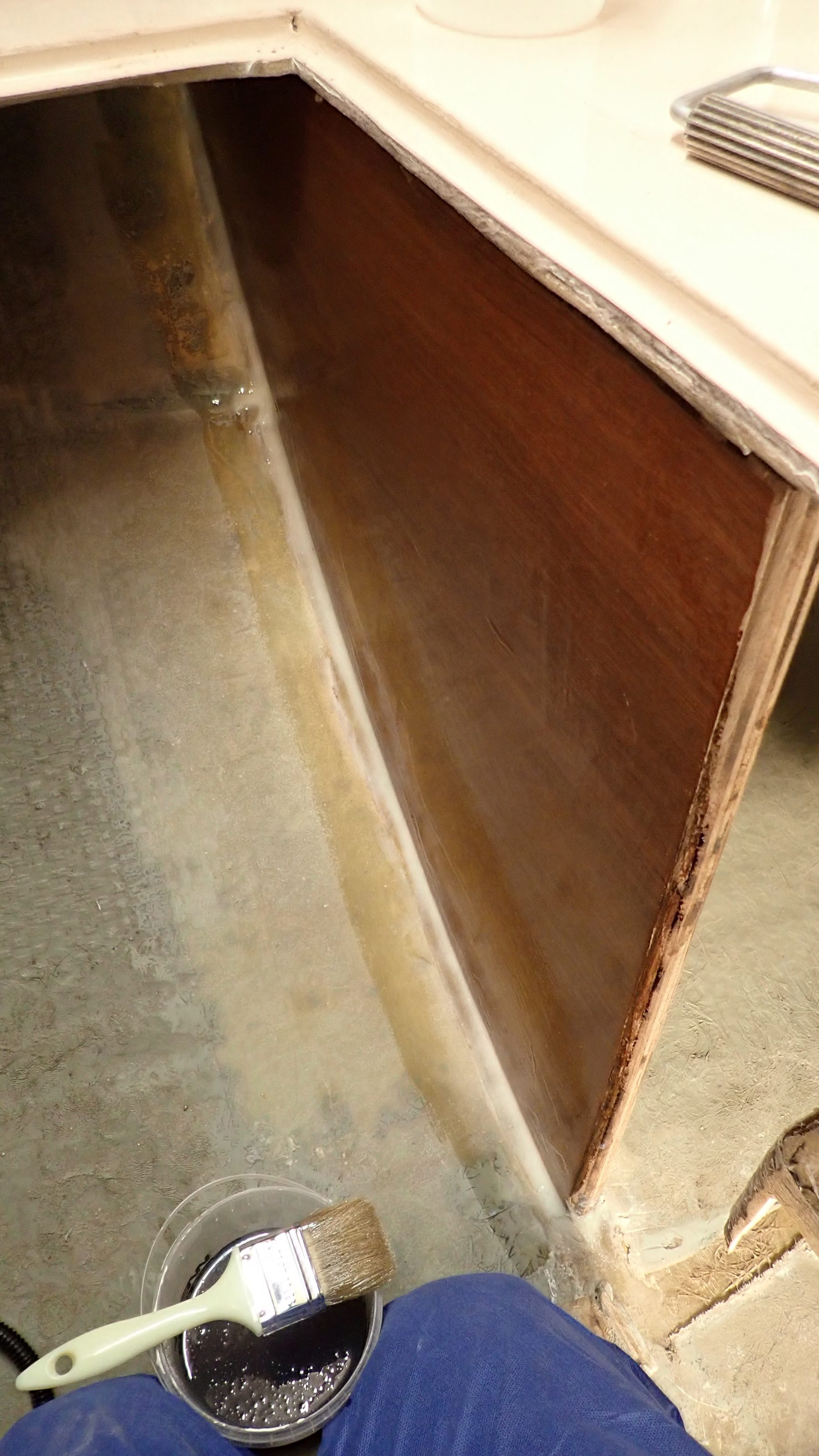
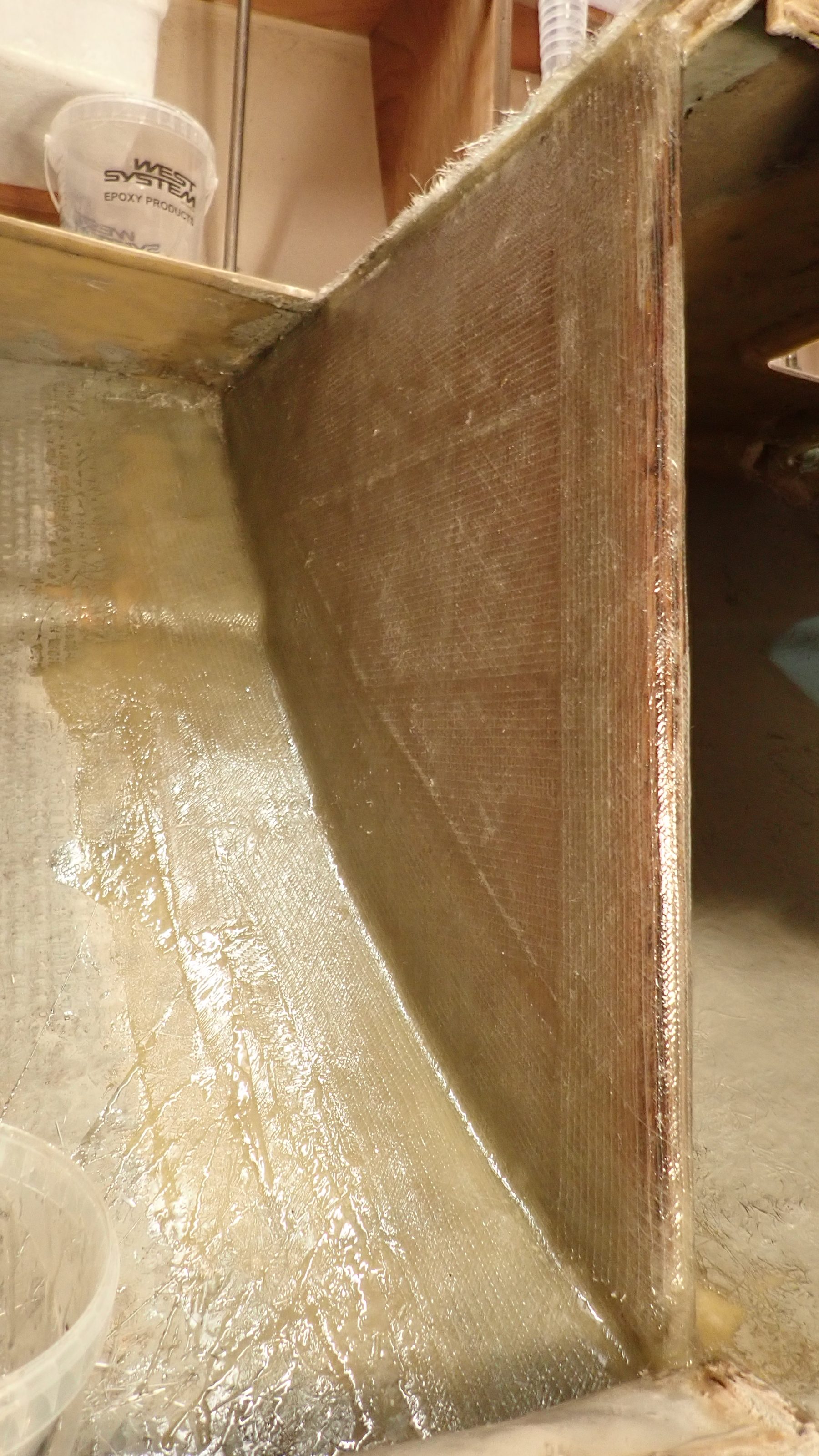
I epoxied a panel vertically into place and a couple of feet forward I epoxied in another Nidaplast panel, which would act as a shelf to take the load of the front of the new shaft tube and stern gland.
Just to make life awkward, we had to relocate the propshaft into its usual orientation, as if dangling upside down, in a small hole, with just enough room for one arm and my head was not hard enough.
You just have to love this job sometimes………


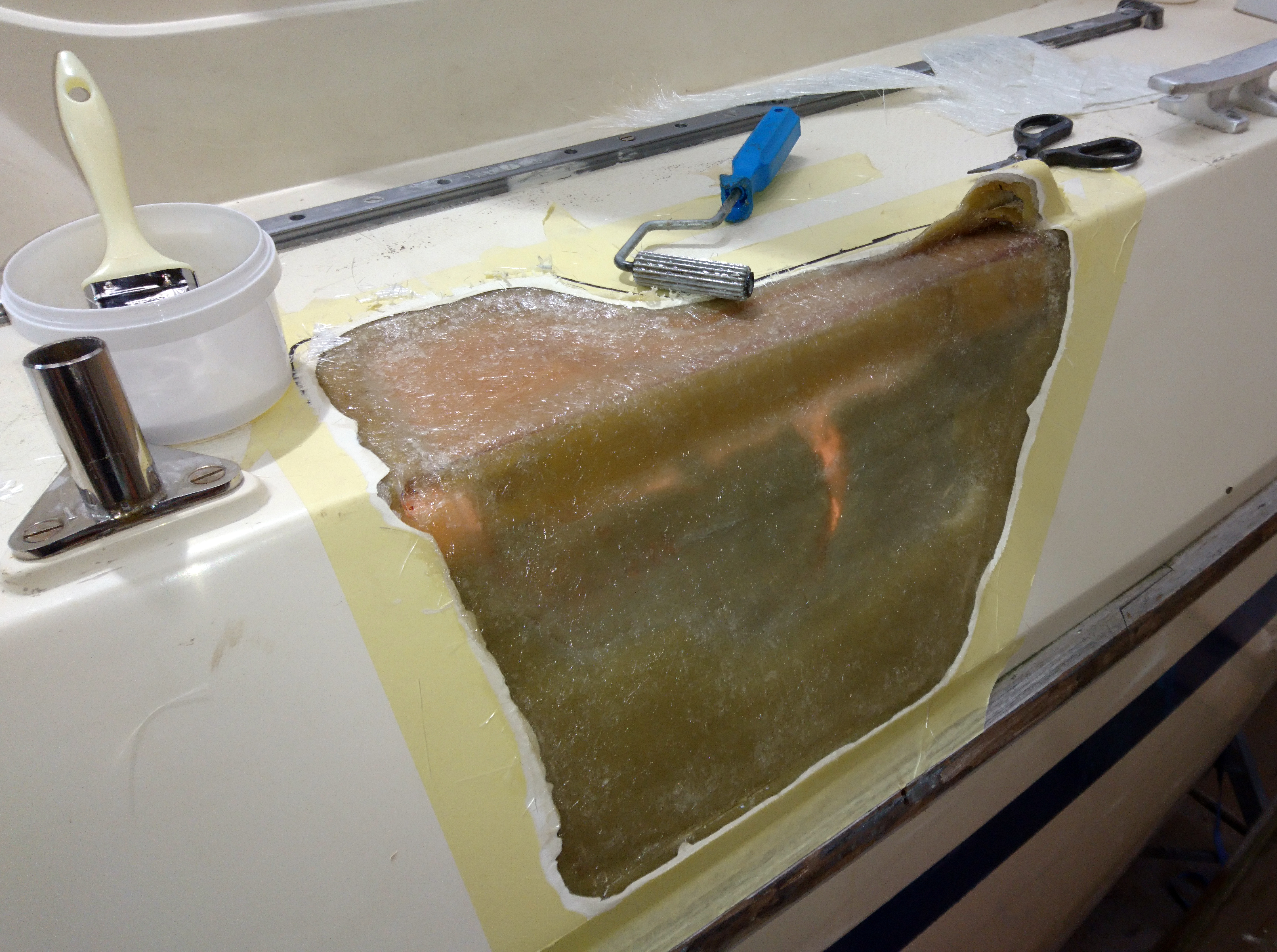
The void aft of the vertical panel was filled with Pro-Set expanding closed cell foam.
This foam is much, much stronger and stiffer than the usual builders merchant expanding foam and it also has very good bonding performance.
Closed cell is again important as it won’t absorb any water.
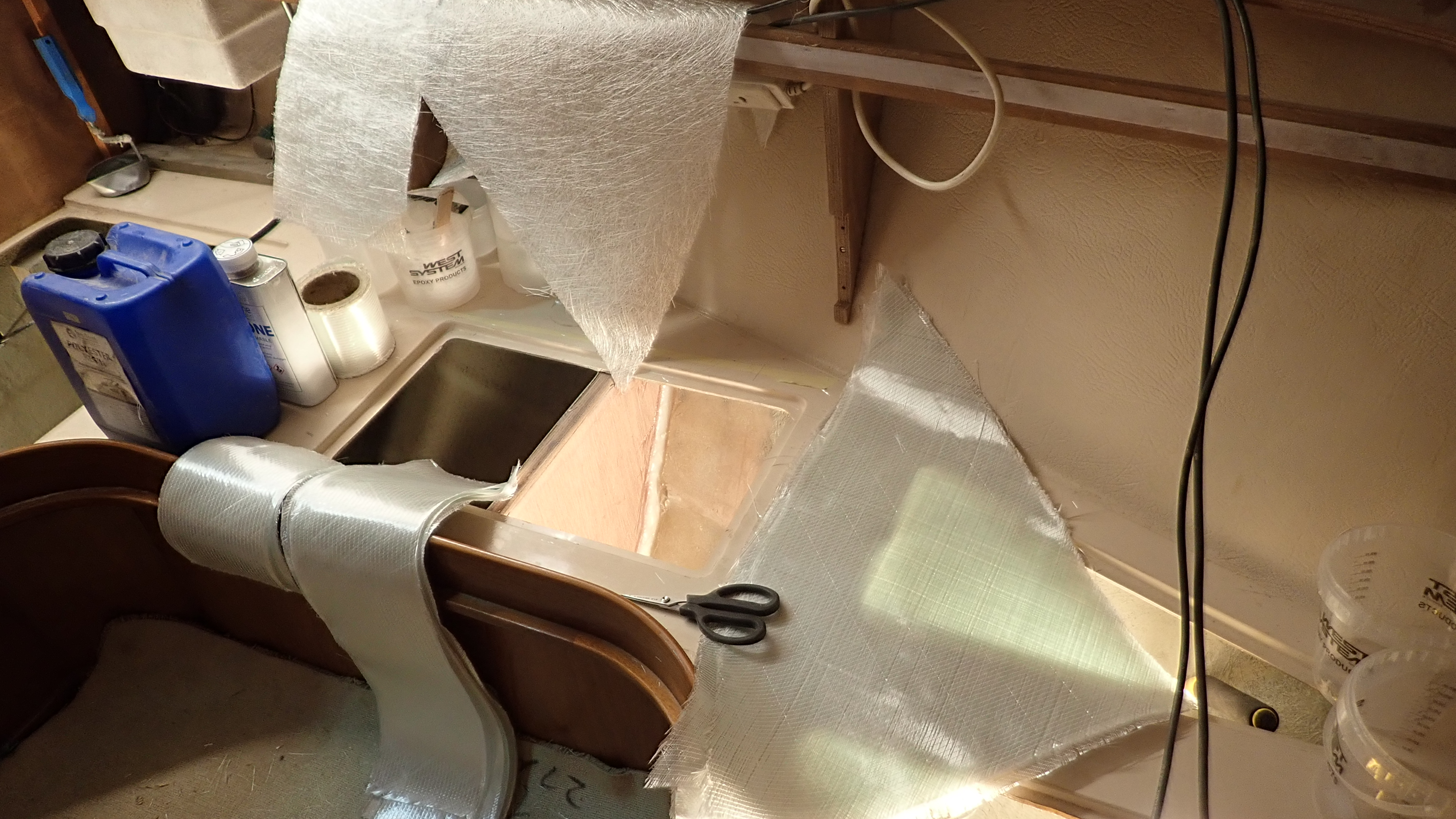
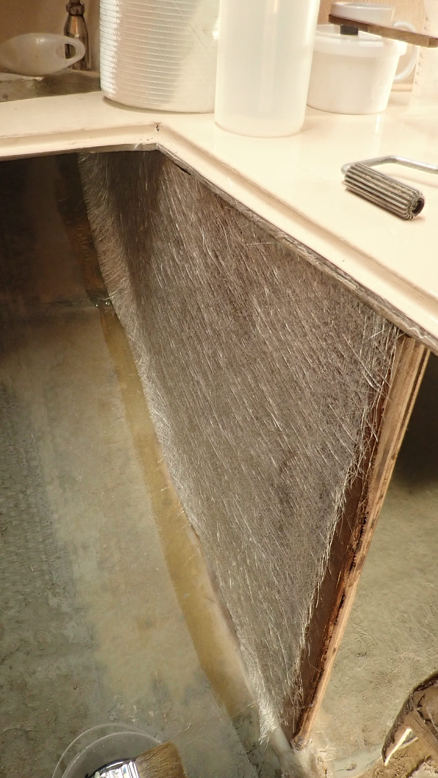
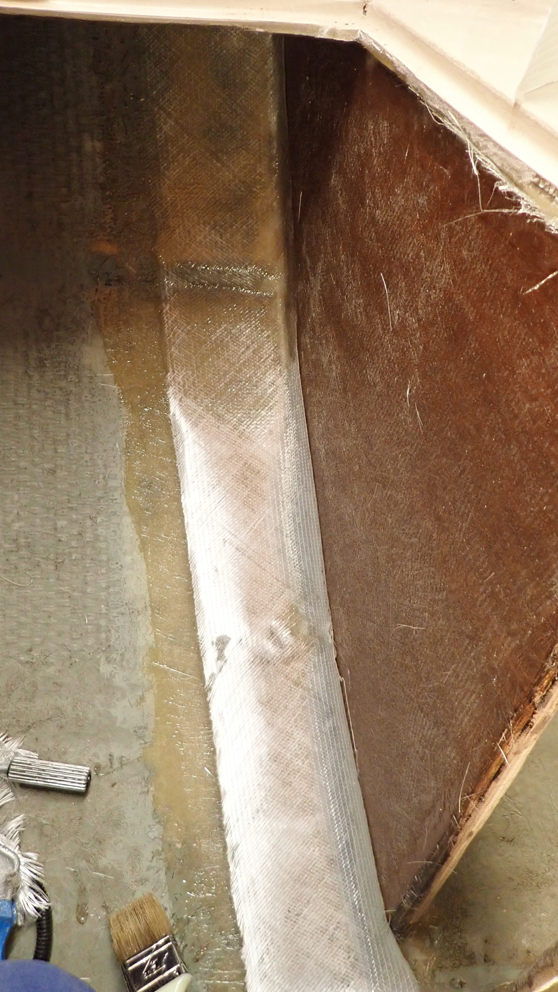
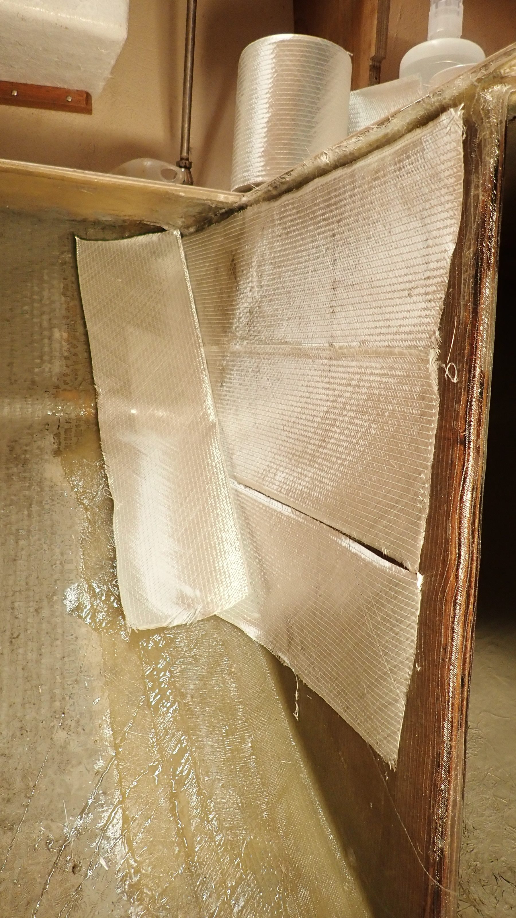
Once the foam had set hard it was trimmed flat and I applied five layers of 450g woven cloth on top and round and down the front of the panel.
Note I’d taped the propshaft to make it easier to remove any epoxy afterwards.
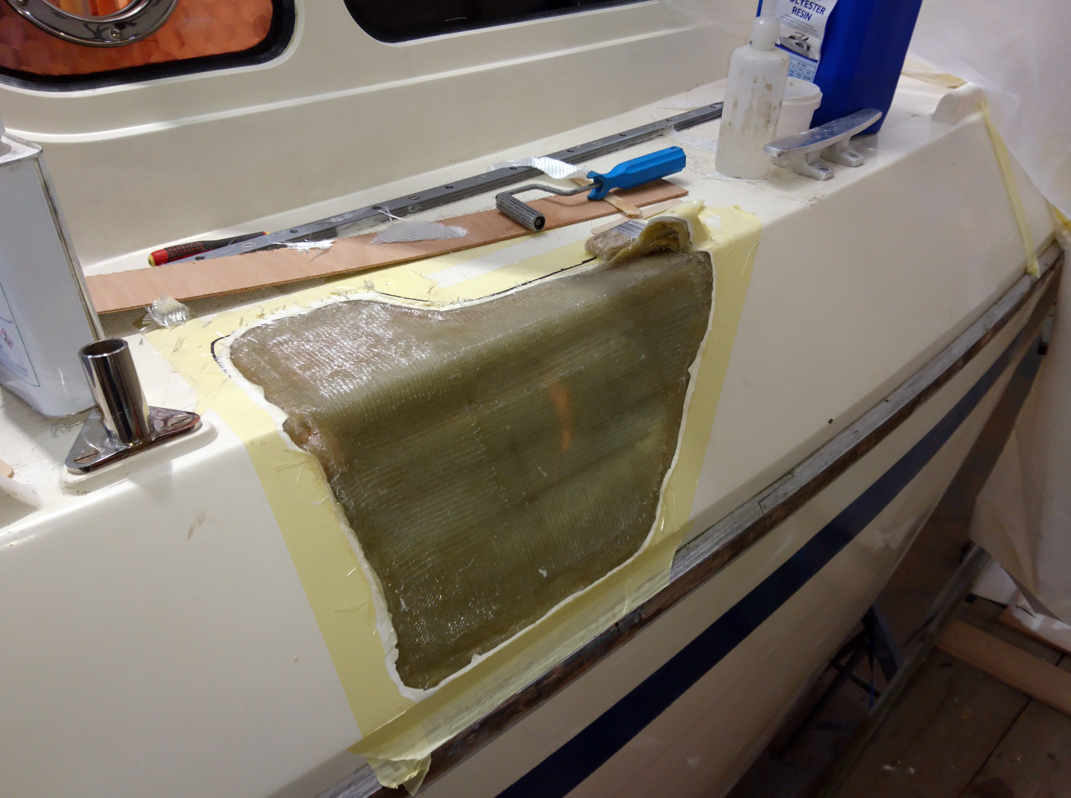
Next we made some tube supports out of softwood with the plan that these would sit on the new shelf and support the new grp propshaft tube.
Note the wooden wedges stuck up the tube to keep the propshaft central to the tube.


It’s at this point its essential to ensure we have perfect alignment.
So the propshaft was re-attached to the gearbox coupling and outside we chocked the propshaft so that it exited the keel exactly central to the exit hole.
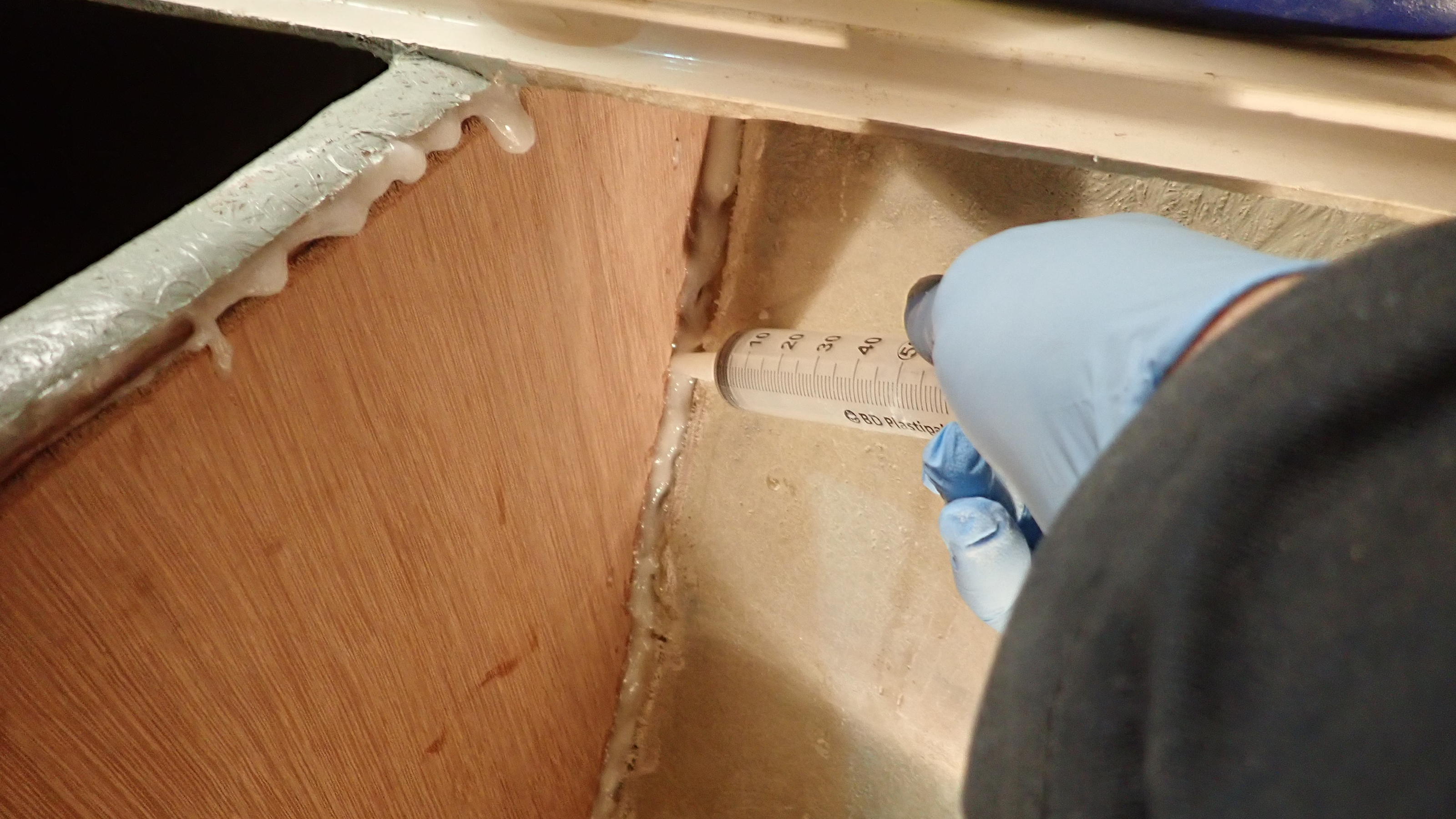
Once this had been achieved and chocked into position I taped up around the sterntube on the outside to stop any glass and resin from the inside leaking out.
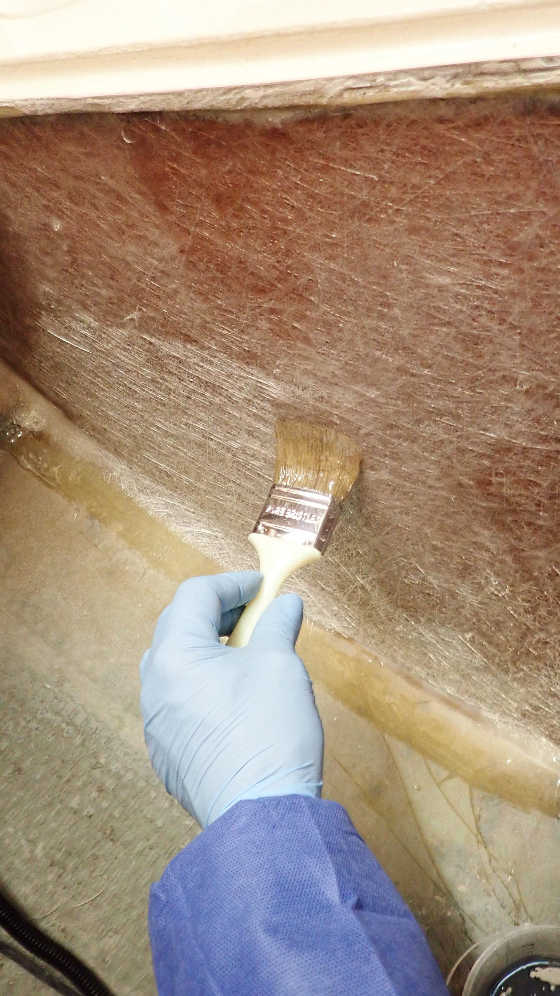
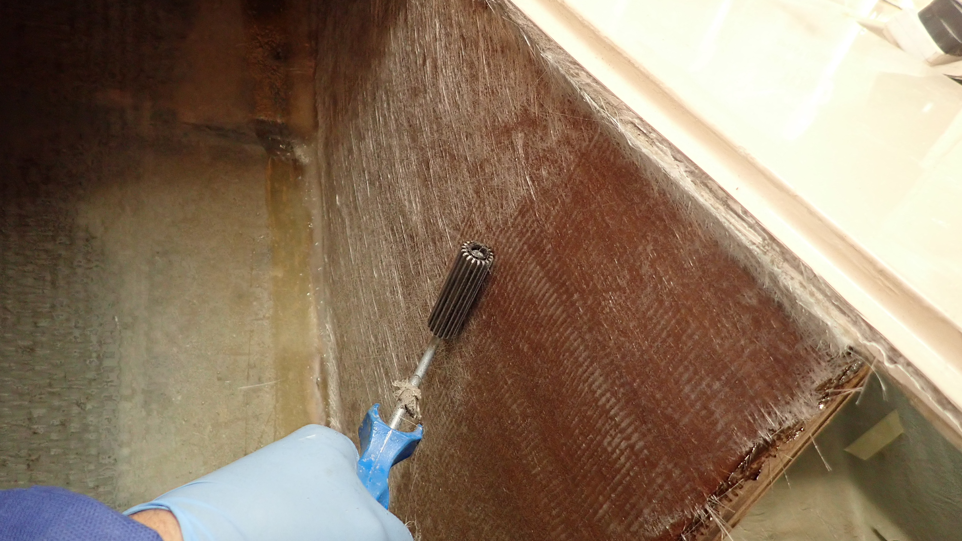
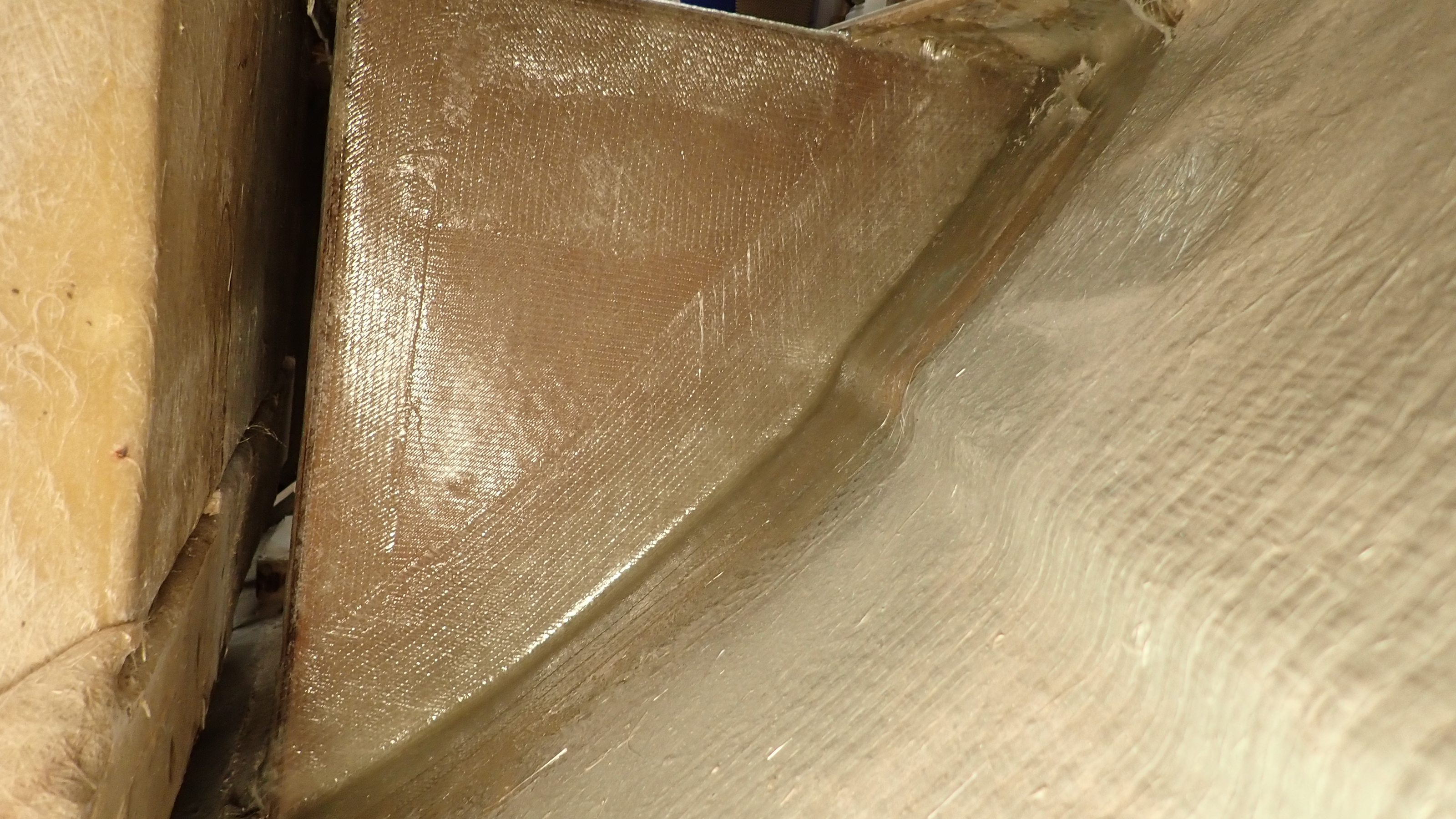
Back in my hole again I injected some thickened epoxy under the tube with a large syringe and then glassed the tube into place, using a mixture of 250g bi-axial and some 450g heavy weave cloth.
After checking the shaft alignment was still ok, I glassed in the front tube supports and sterntube into place.
Again mainly using 250g bi-axial but around the wooden tube supports I applied a couple of layers of 300g powder bound chopped strand mat.
Note that you must only use powder bound csm with epoxy resin as the usual chopped strand mat (csm) is emulsion bound and the styrene in Polyester resin dissolves the emulsion. Epoxy will not dissolve the emulsion in standard csm, so if you use it you can end up with a very sticky mess.


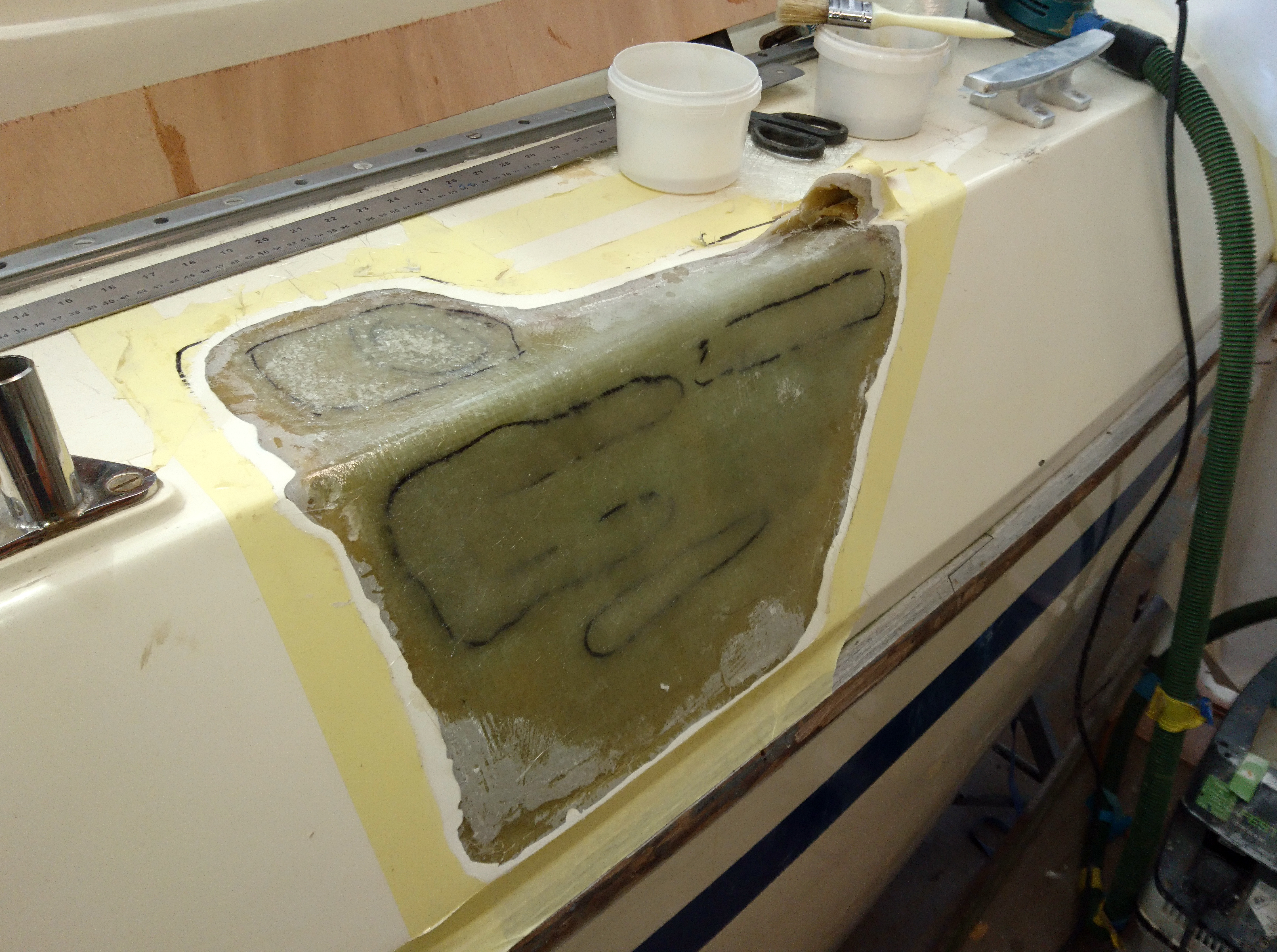
Once the glass had cured we could fit the new sterngland and greaser and thankfully I could exit the hole.
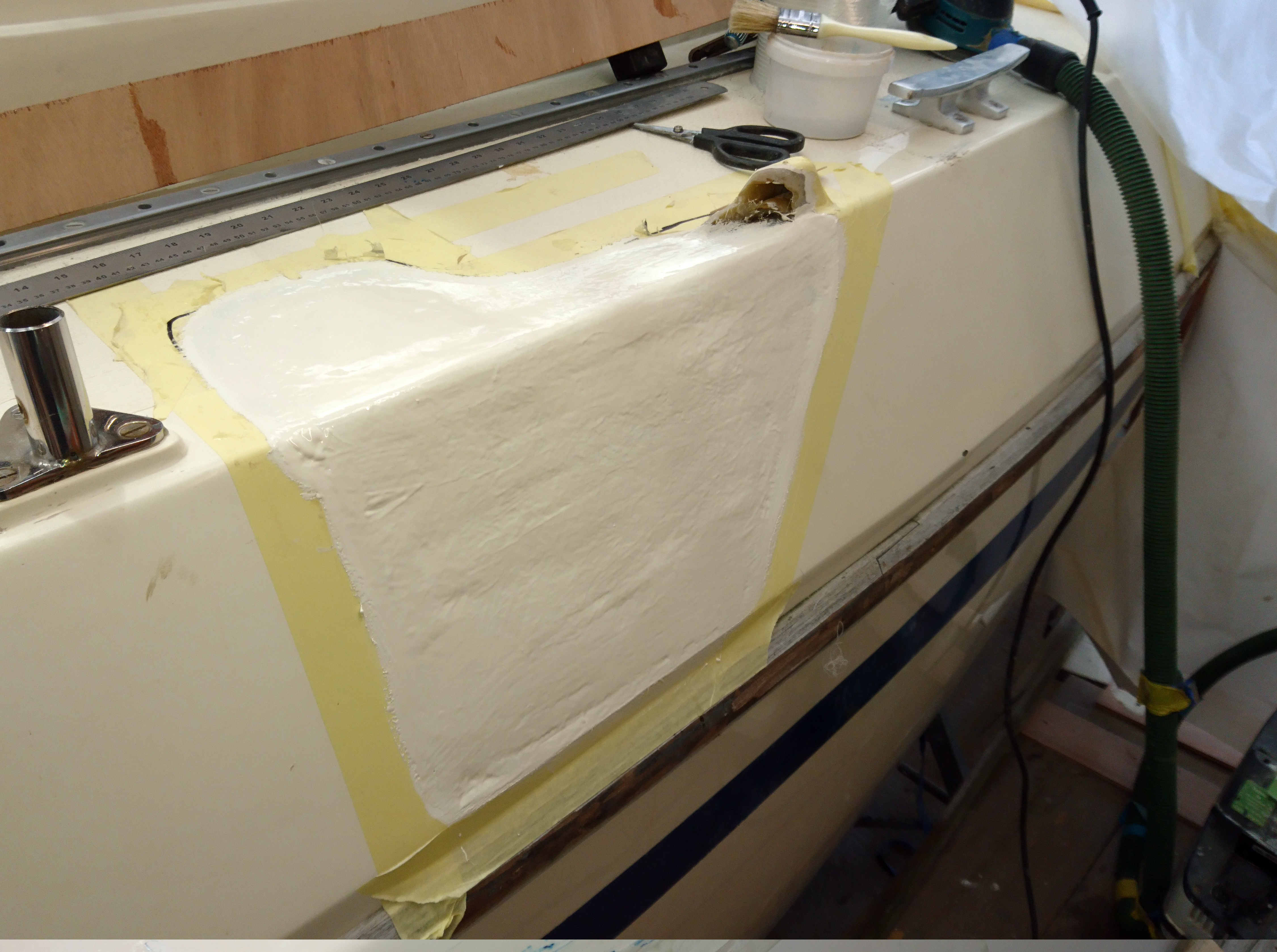
Outside, I’d already ground back the keel and so after a dust off applied five layers of 250g bi-axial cloth.
Once this had cured it was keyed and a couple of coats of epoxy two pack primer was applied followed by a tie coat and then antifoul.
I still shiver at the thought of the owner, sailing out at sea with his youngster not realising he was sailing a sinking timebomb.


(Photos HT-001, HT-002)
Have you ever suffered from “Where the hell is that Fl.G.2s?”or “Is that red light moving off the port bow?” and “is the angle changing?”
On a night passage one of my biggest dislikes is peering forward through wobbly, opaque plastic windows, having to stick my head out into the elements every few minutes to try and pacify my increasing paranoia.
I found myself looking longingly at Hallberg Rassy’s, Najad’s and even the occasional Bavaria thinking maybe I could make something to fit my mid 80’s ¾ tonner.
I looked about on the internet at after-market examples and frankly nothing really looked like it would work on my boat.
Apart from the improved visibility I had a number of additional provisos that the design needed meet.
1. Standing at the helm I need to be able to see the bow.
2. Without a raised cockpit combing the bottom of the hard-top needed to extend well aft of the coachroof to deflect water running down the windward sidedeck.
3. There had to be enough clearance for the main winch handles, good access to clutches etc.
4. Long and strong enough to take the weight of 2 x 100w solar panels.
5. The canvas top needs to fold down easily.
6. The design needs to match the overall style of the boat.


(Photos HT-003, HT-004, HT-006)
I took a number of photos of the boat, printed them out and then drew what I wanted which at least gave me an idea of angles of the windows.
With these ideas in mind I cut some panels out of scrap plywood and taped them in position with masking tape.
I took photos, walked away and looked from distance from various angles and concluded that mk1 plywood mock-up wasn’t big enough.
However I had at least found a process that would work.


(Photos HT-007, HT-008, HT-009)
Mk2 was better and I adjusted various angles and re-taped a number of times.
I checked winch handle clearance, looked over the top from my normal, tiller between the knees entering leaving harbour position and carried on adjusting the position of each panel until I was happy.
I had only templated the centre and port side so I dismantled the panels and reassembled them to check the starboard side was the same and give or take a few mm it was the same.
Not something you can guarantee, especially on boats built in the 80’s.


(Photos HT-010, HT-011, HT-012)
I replicated the 9 plywood panels in some offcuts of shower-board. I could have used anything which had a nice shiny surface like melamine faced ply or even chipboard.
This time I assembled the structure using resin tape on the joints, though parcel tape would have worked just as well.
Each joint was glued using a hot glue gun and I added stiffening to the larger front panel.
At this point I also added a 40mm wide flange around the top edge which would act to stiffen the whole structure.
As the outer surface would end up being the visible inside of the hardtop, I waxed and polished so when the time came the board would part easily from the glass fibre.


(Photos HT013, HT-014)
I checked on the weather as I needed a full day without the prospect of rain.
I applied three coats of white gelcoat.
The outside temp was around 14deg so it took around an hour between each coat, even though I’d been quite generous with the catalyst.
I find that csm has a better bond to gelcoat than woven cloth so after lunch I applied an initial layer of 250g chopped strand mat (csm).
This was followed by three layers of 250g biaxial cloth.
I taped up a strip around 2” wide, internally around the deck where the hard top will land and using 4” wide plain weave tape, glassed a flange all the way round.
This provided a perfectly matched base between the hardtop and deck.


(Photos HT019, HT-020, HT-021)
After a few days I lifted the whole assembly off the boat and trimmed the edges and sanded the outer surface down with a course grit paper and then removed all the dust to provide a good key for the next stage.
I needed the structure to be stiff but at the same time I wanted to avoid too much weight.
The obvious solution was to use Carbon fibre.
Contrary to popular belief its perfectly possible to use Carbon fibre with polyester resin.
Admittedly its not as good as using epoxy resin but its still very good.
I used a plain weave, 100mm wide, 240g carbon fibre tape which at less than £5 a meter won’t break the bank.
In the high stress areas I applied four layers of carbon followed by a couple more layers of normal 300g biaxial.


(Photos HT-023)
After the glass had cured to the touch I trimmed all the excess and gave the outside a good sand to provide a flat surface and a key for outer layers of gelcoat.
I applied three thin coats of normal gelcoat followed by a final coat of gelcoat with added wax in styrene, added roughly in the same quantity as the catalyst. Otherwise known as topcoat gelcoat or flowcoat.
Its important when coating gelcoat to use multiple thin coats rather than a couple of thick coats otherwise there is a strong chance you will trap small air bubbles which when sanding back will appear and they are a real pain to get rid of.
Normal gelcoat will not “go off” unless you remove the oxygen. The idea of the wax additive is that during the curing process the wax comes to the surface sealing off the gelcoat from the air.
It’s worth using a roller for the top coat or even a good quality brush as the flatter you get this final coat the less sanding is required.

(Photos HT024, HT-025, HT-026)
To understand how to get a nice shiny finish you need to work backwards in the process.
The final shining process is using a cutting paste and buffing.
Cutting paste will take out 1000 or 1500 grit scratches.
1000grit wet and dry will take out 320 or 400 grit orbital sander scratches.
320grit dry paper will remove 180 or 240grit orbital sander scratches.
So my usual process is firstly scribble all over the surface using a permanent marker and sand this off using 240grit paper.
The scribble allows you clearly see the highs and lows in the surface of the gelcoat.
This technique is repeated using 400grit and then 1500grit and finally cutting with a suitable cutting paste.


(Photos HT-027, HT-028, HT-029, HT-030, HT-031, HT-032)
The hardtop was then moved back to the boat for a test fit.
After the addition of the carbon and other glass plus the gelcoat I needed to be sure the structure had not twisted or moved about too much before the windows were fitted.
This pretty much the last opportunity to make adjustments as after the windows are fitted it would become far more difficult.


(Photos HT-033)
My initial plan was to use toughened glass for the windows but the cost was pretty high especially on an unproven project, plus due to the weight of the glass I’d have the added complication of adding an internal flange to hold the glass in place.
So I opted to use the much lighter 8mm Acryglas, although any of the acrylic glass materials would have been fine.
I cut each one out using a jigsaw with a fine metal blade and then, as the edges will be visible inside, I sanded the edges with 240grit paper to get the jigsaw scratches out and then with 500 then 1000 grit wet and dry.

(Photos HT-034, HT-035)
The window panels were cut leaving a 30mm overlap all the way round.
This strip was taped off and I sanded the mating area using 80grit paper to provide a good key.
I used white Sabatack 750 to bond the windows in place and clamping them for 24 hours.


(Photos HT-036, HT-038, HT-040)
I bought a couple of lengths of 15mm diameter copper tube and having decided on suitable pivot positions bent the tube to support the canvas top.
Once I was happy with the copper tube which is very easy to bend I copied each frame using 20mm 316 stainless steel though I did consider using aluminium.
I’d previously bought some waterproof cordura type canvas and had a largish off cut so having taped the frames into the correct position I draped the material over and again using tape and some ss screws manoeuvred, cut, tweaked the canvas into position and by total surprise I found that apart from a couple of pleats I didn’t have to make panels.
Now I can feel you cover makers wincing here at my rather amateurish attempts at cover making but this was a Wednesday and we were sailing to Holland on the Saturday so needs must.
However after an evening sewing hems and webbing to stress areas, velcro to hold everything in place, it all came together pretty well, plus is was £600 cheaper than I’d been quoted!
I bonded down the hardtop to the deck using Sabatack and this was weighted down for 24 hours.
I gave the whole structure a dammed great tug about and concluded that I didn’t need any through bolts which pleases me no end as I hate with a passion drilling holes in my deck.


(Photo HT-041)
Its been across the pond a couple of times, had a couple of green water hits as we’ve rounded Orford Ness in a blow.
Has seen off the winter storms on her rather exposed mooring and still has not attracted the ire of SWMBO which in our house is 90% of the battle, though we’ve had words on the sailcover, dodgers and now sprayhood being three different colours.
Overall the hardtop has done exactly what I wanted and worked really well on the two night passages I’ve made with it.
In fact we now have a new prime location when its cold and wet, which is sitting in the companion way entrance, on a cushion looking out through the windows, cosy as a bug in rug.

(Photos HT-001, HT-002)
(hover over photo for its number)
Have you ever suffered from “Where the hell is that Fl.G.2s?”or “Is that red light moving off the port bow?” and “is the angle changing?”
On a night passage one of my biggest dislikes is peering forward through wobbly, opaque plastic windows, having to stick my head out into the elements every few minutes to try and pacify my increasing paranoia.
I found myself looking longingly at Hallberg Rassy’s, Najad’s and even the occasional Bavaria thinking maybe I could make something to fit my mid 80’s ¾ tonner.
I looked about on the internet at after-market examples and frankly nothing really looked like it would work on my boat.
Apart from the improved visibility I had a number of additional provisos that the design needed meet.
1. Standing at the helm I need to be able to see the bow.
2. Without a raised cockpit combing the bottom of the hard-top needed to extend well aft of the coachroof to deflect water running down the windward sidedeck.
3. There had to be enough clearance for the main winch handles, good access to clutches etc.
4. Long and strong enough to take the weight of 2 x 100w solar panels.
5. The canvas top needs to fold down easily.
6. The design needs to match the overall style of the boat.
(Photos HT-003, HT-004, HT-006)
I took a number of photos of the boat, printed them out and then drew what I wanted which at least gave me an idea of angles of the windows.
With these ideas in mind I cut some panels out of scrap plywood and taped them in position with masking tape.
I took photos, walked away and looked from distance from various angles and concluded that mk1 plywood mock-up wasn’t big enough.
(Photos HT-007, HT-008, HT-009)
Mk2 was better and I adjusted various angles and re-taped a number of times.
I checked winch handle clearance, looked over the top from my normal, tiller between the knees entering leaving harbour position and carried on adjusting the position of each panel until I was happy.
I had only templated the centre and port side so I dismantled the panels and reassembled them to check the starboard side was the same and give or take a few mm it was the same.
Not something you can guarantee, especially on boats built in the 80’s.
(Photos HT-010, HT-011, HT-012)
I replicated the 9 plywood panels in some offcuts of shower-board. I could have used anything which had a nice shiny surface like melamine faced ply or even chipboard.
This time I assembled the structure using resin tape on the joints, though parcel tape would have worked just as well.
Each joint was glued using a hot glue gun and I added stiffening to the larger front panel.
At this point I also added a 40mm wide flange around the top edge which would act to stiffen the whole structure.
As the outer surface would end up being the visible inside of the hardtop, I waxed and polished so when the time came the board would part easily from the glass fibre.
(Photos HT013, HT-014)
I checked on the weather as I needed a full day without the prospect of rain.
I applied three coats of white gelcoat.
The outside temp was around 14deg so it took around an hour between each coat, even though I’d been quite generous with the catalyst.
I find that csm has a better bond to gelcoat than woven cloth so after lunch I applied an initial layer of 250g chopped strand mat (csm).
This was followed by three layers of 250g biaxial cloth.
I taped up a strip around 2” wide, internally around the deck where the hard top will land and using 4” wide plain weave tape, glassed a flange all the way round.
This provided a perfectly matched base between the hardtop and deck.
(Photos HT015, HT-016, HT-017, HT-018)
The next day I marked out the position of each window.
In the corner of each window a used a 3” hole cutter which roughly matched the radius of the other windows on the boat. For the smaller radius corners I used an appropriately smaller hole cutter.
Then I used the most useful tool in a boatbuilders inventory, a battery powered Fein Cutter, to carefully cut out the windows.
(Photos HT019, HT-020, HT-021)
After a few days I lifted the whole assembly off the boat and trimmed the edges and sanded the outer surface down with a course grit paper to provide a good key for the next stage.
I needed the structure to be stiff but at the same time I wanted to avoid too much weight.
The obvious solution was to use Carbon fibre.
Contrary to popular belief its perfectly possible to use Carbon fibre with polyester resin.
Admittedly its not as good as using epoxy resin but its still very good.
I used a plain weave, 100mm wide, 240g carbon fibre tape which at less than £5 a meter won’t break the bank.
In the high stress areas I applied four layers of carbon followed by a couple more layers of normal 300g biaxial.
(Photos HT-023)
After the glass had cured to the touch I trimmed all the excess and gave the outside a good sand to provide a flat surface and a key for outer layers of gelcoat.
I applied three coats of normal gelcoat followed by a final coat of gelcoat with added wax in styrene, added roughly in the same quantity as the catalyst. Otherwise known as topcoat gelcoat or flowcoat.
Normal gelcoat will not “go off” unless you remove the oxygen. The idea of the wax additive is that during the curing process the wax comes to the surface sealing off the gelcoat from the air.
It’s worth using a roller for the top coat or even a good quality brush as the flatter you get this final coat the less sanding is required.
(Photos HT024, HT-025, HT-026)
To understand how to get a get a nice shiny finish you need to work backwards in the process.
The final shining process is using a cutting paste and buffing.
Cutting paste will take out 1000 or 1500 grit scratches.
1000grit wet and dry will take out 320 or 400 grit orbital sander scratches.
320grit dry paper will remove 180 or 240grit orbital sander scratches.
So my usual process is firstly scribble all over the surface using a permanent marker and sand this off using 240grit paper.
The scribble allows you clearly see the highs and lows in the surface of the gelcoat.
This technique is repeated using 400grit and then 1500grit and finally cutting with a suitable cutting paste.
(Photos HT-027, HT-028, HT-029, HT-030, HT-031, HT-032)
The hardtop was then moved back to the boat for a test fit.
After the addition of the carbon and other glass plus the gelcoat I needed to be sure the structure had not twisted or moved about too much before the windows were fitted.
(Photos HT-033)
My initial plan was to use toughened glass for the windows but the cost was pretty high especially on an unproven project, plus due to the weight of the glass I’d have the added complication of adding an internal flange to hold the glass in place.
So I opted to use the much lighter 8mm Acryglas, although any of the acrylic glass materials would have been fine.
(Photos HT-034, HT-035)
I cut out the window panels leaving a 30mm overlap all the way round.
This strip was taped off and I sanded the mating area using 80grit paper to provide a good key.
I used white Sabatack 750 to bond the windows in place and clamping them for 24 hours.
(Photos HT-036, HT-038, HT-040)
I bought a couple of lengths of 15mm diameter copper tube and having decided on suitable pivot positions bent the tube to support the canvas top.
Once I was happy with the copper tube which is very easy to bend I copied each frame using 20mm 316 stainless steel though I did consider using aluminium.
I’d previously bought some waterproof cordura type canvas and had a largish off cut so having taped the frames into the correct position I draped the material over and again using tape and some ss screws manoeuvred, cut, tweaked the canvas into position and by total surprise I found that apart from a couple of pleats I didn’t have to make panels.
Now I can feel you cover makers wincing here at my rather amateurish attempts at cover making but this was a Wednesday and we were sailing to Holland on the Saturday so needs must.
However after an evening sewing hems and webbing to stress areas, velcro to hold everything in place, it all came together pretty well, plus is was £600 cheaper than I’d been quoted!
I bonded down the hardtop to the deck using Sabatack and this was weighted down for 24 hours.
I gave the whole structure a dammed great tug about and concluded that I didn’t need any through bolts which pleases me no end as I hate with a passion drilling holes in my deck.
(Photo HT-041)
Its been across the pond a couple of times, had a couple of green water hits as we’ve rounded Orford Ness in a blow.
Has seen off the winter storms on her rather exposed mooring and still has not attracted the ire of SWMBO which in our house is 90% of the battle, though we’ve had words on the sailcover, dodgers and now sprayhood being three different colours.
Overall the hardtop has done exactly what I wanted and worked really well on the two night passages I’ve made with it.
In fact we now have a new prime location when its cold and wet, which is sitting in the companion way entrance, on a cushion looking out through the windows, cosy as a bug in rug.


Back in November I covered a repair to a Southerly that had been T-boned.
Well the job was finished and I was just tidying up when the owner asked me to see if I could locate his fluxgate compass.
I stuck my head in various lockers and other likely places it might have been fitted.
This 1999 boat is in very good order, all the varnish, trim, flooring and upholstery looking like is on a boat a couple of years old, so I really wasn’t looking for trouble.
The following shots were taken after I’d finished the job but they could have equally been taken before I started.
When I checked under the raised seating area I noticed that the gelcoat wash that had been put on the plywood bulkheads had cracked in a couple of places.
I poked one of these marks with my finger and I was frankly astonished that my finger went right through the plywood.
Under this raised seating area is long length of plywood that stretches from the water tank, in front of the galley area, to the main lateral bulkhead splitting the saloon from the forward cabin.
Off this longitudinal bulkhead there are two sheathed plywood locker sides and also the two port side chain plate knees.
It appears that when the builder fitted this plywood structure, they simply butted each section of plywood together, before glassing it in place and then sheathing it.
However in a couple of places, on the less important locker sides, they didn’t sheath the panels entirely, leaving an area around 4″ by 12″ in the middle of the panel that just had a coating of gelcoat.
Not much to look at really and easy to ignore.
I didn’t expect to be able to push my finger through though.
After a few minutes water started to drain out of the finger hole into the bottom of the locker.
I knew we were in trouble when an area at least two feet above the bilge was obviously rotten.
I poked a little more at the forward locker side and it was found to be water logged mush, though strangely no smell at all.
With a multitool I cut out the glass tabling around the panel and scooped out all the soaked rotten wood.
I then turned my attention to the longitudinal bulkhead and this was slightly dryer but was still wet and crumbled in my hand.
I followed this process gradually working my way round the structure removing all the rotten wood.
Things got a bit more serious when looking at the main chainplate knees.
Whilst from the outside the knees looked fine, if you look at the photo carefully you can see the bolts are at a slight angle.
In fact four or five of the nuts were only finger tight.
With the chainplate bolts removed we could inspect the backing plate, which surprised us as it was made from aluminum plate rather than 316 Stainless.
All the holes had elongated showing that the plate had raised under load by around 30mm.
Using a hole cutter I drilled out an exploratory 30mm hole through the sheathing to check the Knee core and found nothing but damp dust.
After cutting away the side of the knee it was obvious that the knees would need rebuilding and also the realization that the rig could have come down at any time.
The rest of the interior wood is in excellent condition, as it was isolated from the supporting structure having been fitted as an independent module at a later stage of the build.
In some ways life was made easy in that the wood was in such poor condition that it simply fell away without much effort at all.
After cutting a 30mm core and finding nothing solid I decided to cut one side of the main chain plate knee out.
Initially I cut away small sections of the sheathing to investigate.
Looking aft, it was clear that the water tank would need to be removed to get to the other side of this bulkhead.
These areas cut away quickly became bigger as I tried to track the extent of the problem.
Working in small spaces at impossible angles makes you really appreciate a good Multitool.
Whilst not as sodden as the rest, the plywood in the knee was still crumbling to the touch.
This was the very first photo I took for the owner and the focus was at this stage the soft area next to my finger.
Looking at it again later I noticed the tell tail angle of the chainplate bolts and the fact that one of the bolts had almost wound itself out.
With the backing plate removed it was clear to see how much the chain plate bolts had shifted.
It didn’t take long to clean all the dead wood away leaving one side of the sheathing intact.
We had established that the rot had not effected the main forward lateral bulkhead though given a few more months then this could have been an issue as well.
To inspect further aft we needed to remove the stainless water tank.
In this Southerly this was no mean feat as access to the outlet from the tank is extremely difficult.
How the builder thought is was a good idea to place the outlet on the aft side of the tank, under the galley, is beyond me, especially as the factory fitted calorifier, fridge compressor and associated pipework would all have to be removed to gain any kind of reasonable access to the single jubilee clip securing the outlet water pipe.
In the end after three hours of knuckle grazing effort we managed to get a modified spanner on the tank fitting and with an 1/8 of a turn at a time wound the whole fitting out of the tank.
Removal of the tank was then pretty straight forward although we did notice there was no inspection hatch or obvious way to clean the tank.
So we decided to get the tank modified, blanking the original outlet and fitting a new one on the forward side which would have much easier access and also to fit an inspection hatch.
With the tank removed we could continue the rot chase and with relief it was found not to have continued into any of the galley supporting structure and bulkheads.
The aft chainplate knee however was found to be rotten and had twisted its position almost as much as the main chainplate knee and the water tank locker side would have to be replaced.
Access to the outlet of the water tank was almost impossible to get too.
The outlet pipe runs through the hole next to the lower tank support.
The aft chainplate knee was found to be in as poor condition as the rest, though this flaked away in papery sheets.
It was by now obvious that over time, the connected sheathed plywood sections had rotted due to moisture getting sucked in by capillary action.
However even though we strongly suspected the bottom inside corner of the forward locker to be the initial entry point I couldn’t find any definitive proof.
With this in mind I wasn’t keen to simply replace the wood for the fear of the same problem recurring in future.
Given the excellent condition of the rest of the interior I also needed a solution that didn’t require disassembly of the entire saloon seating area.
So I decided to replace all the panels except for the knees, using a 10mm thick plastic honeycomb core, called Nidaplast, which would then have two layers of 250 gram chopped strand matt laminated to each side.
The resulting panel is stiffer and lighter than plywood , with the obvious additional benefit of there being nothing to rot in the future.
The chainplate knees however would be 25mm marine plywood, due to the compression of the chain plate bolts. The knees would be glassed to the hull and sheaved individually.
I find the easiest way to template an awkward shape is to use 2″ wide strips of hardboard and stick them together using a hot glue gun.
The resulting shape can then be transferred over to the sheet material you wish to use, marked up and cut out.
1, Hardboard strips are glued around the perimeter to create a template.
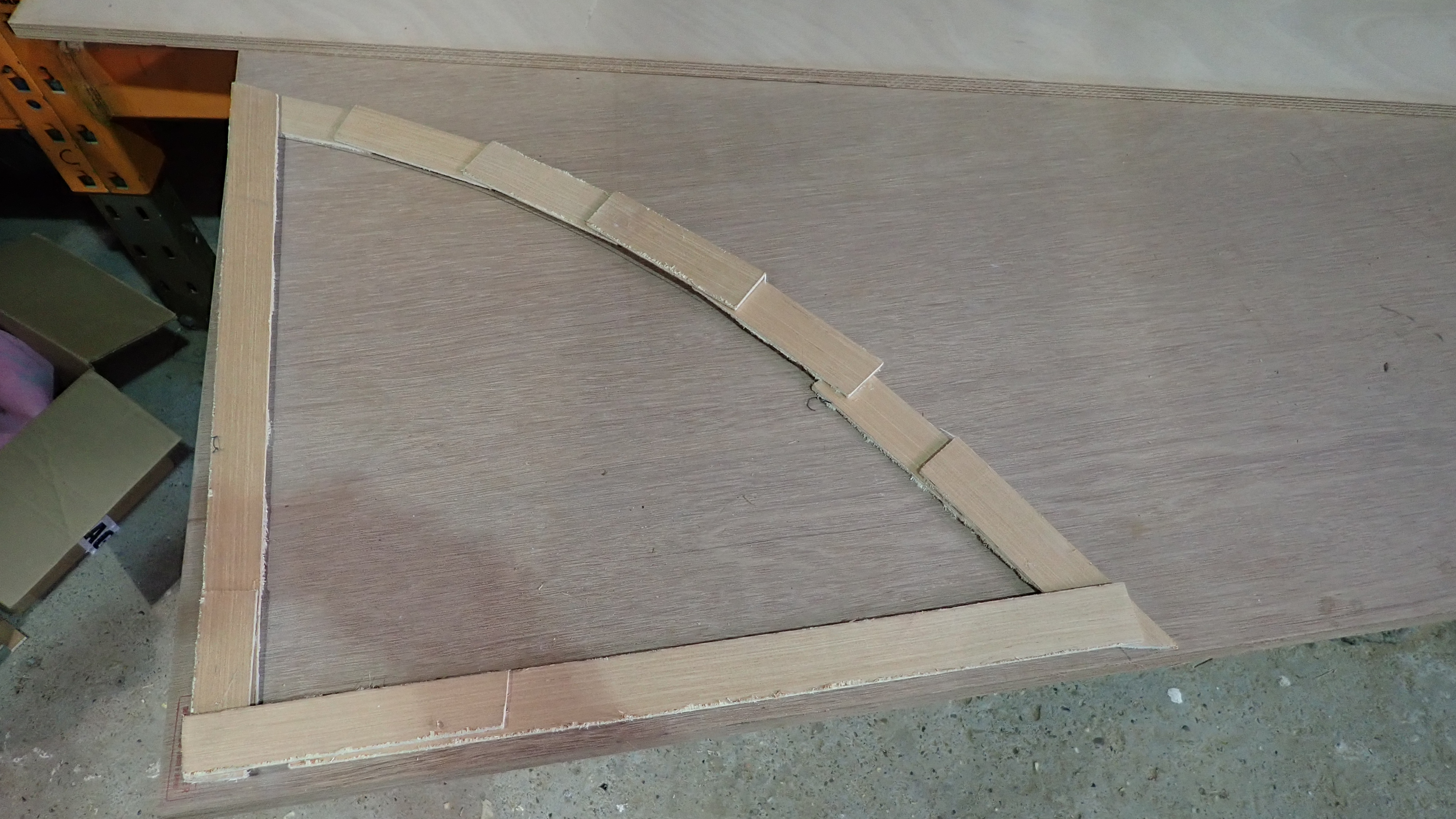
2, The template can then be used to mark up a new panel.
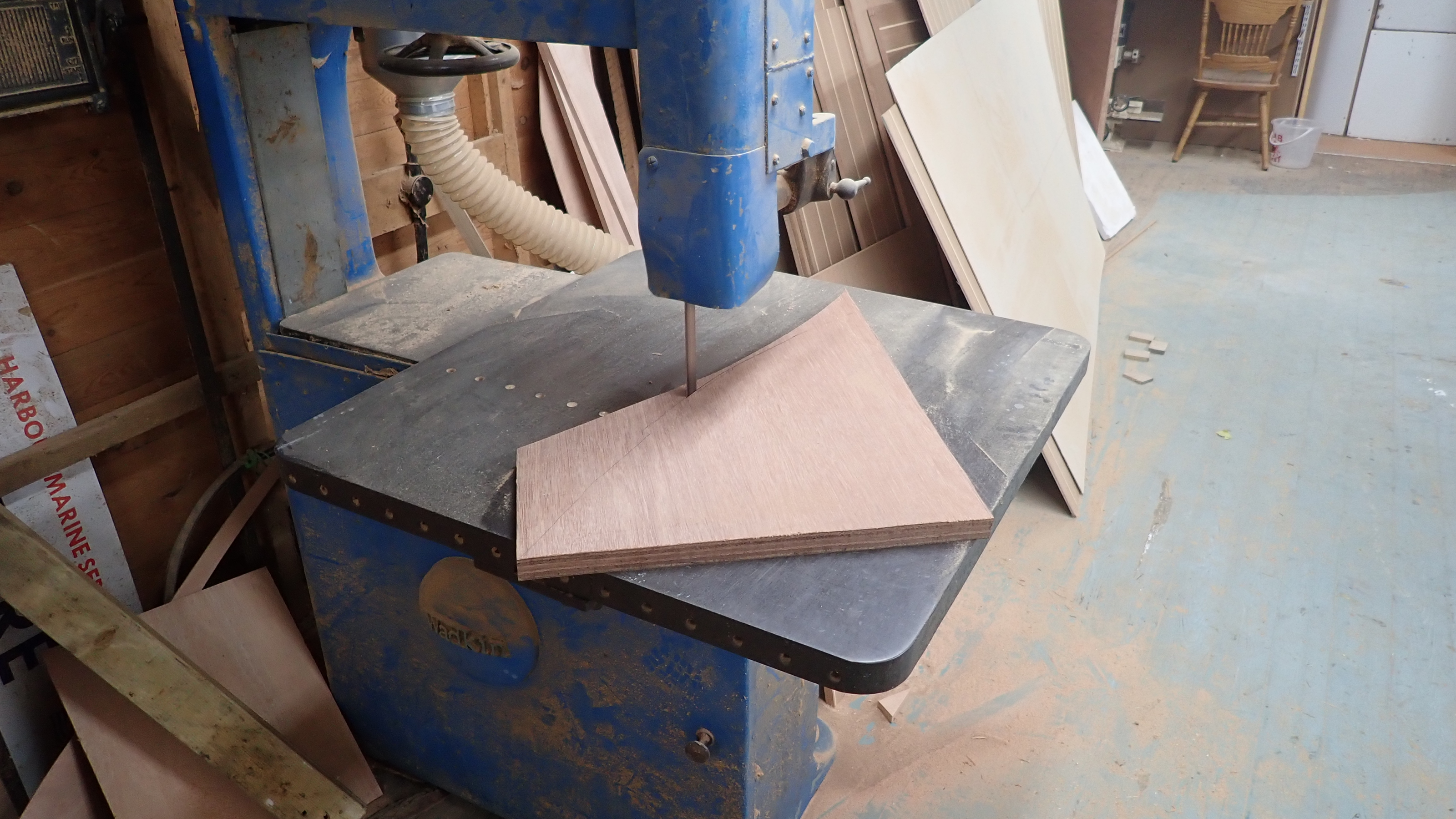
3, Using a jigsaw or bandsaw the new panel is cut out.
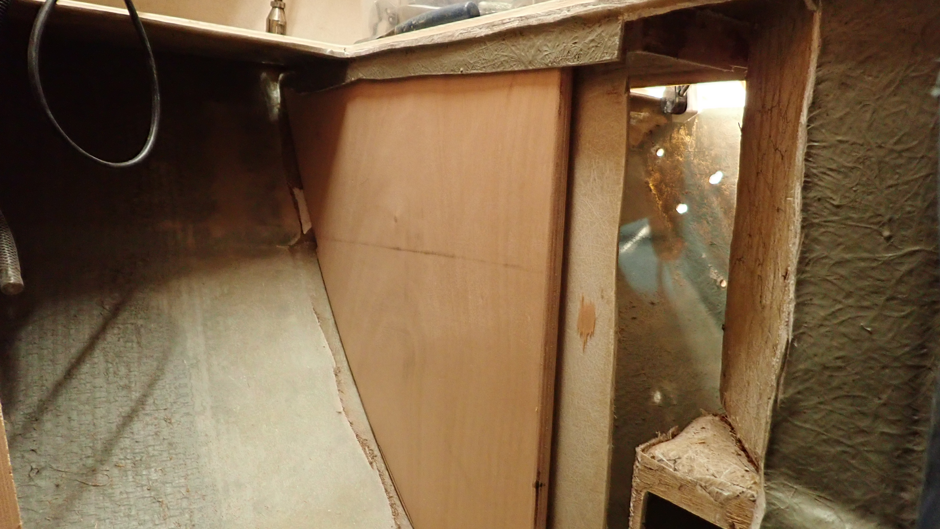
3, Dry fit the panel to check the fit.
When I removed the old rotten wood I removed one side of the sheathing only.
The remaining sheathing side was cleaned and keyed so that it would provide a solid location for the new knee.
The new plywood was given a coat of neat west epoxy and then a thickened mix using 406 colloidal silica was liberally applied to the side of the old sheathing.
The new panel was inserted and clamped into position.
Using a large syringe more epoxy/406 mix was injected into the joints between the knee and the hull.
Then using a tongue depressor an epoxy fillet was created round the edges.
1, We use a large syringe to inject epoxy/406 mix into difficult places.
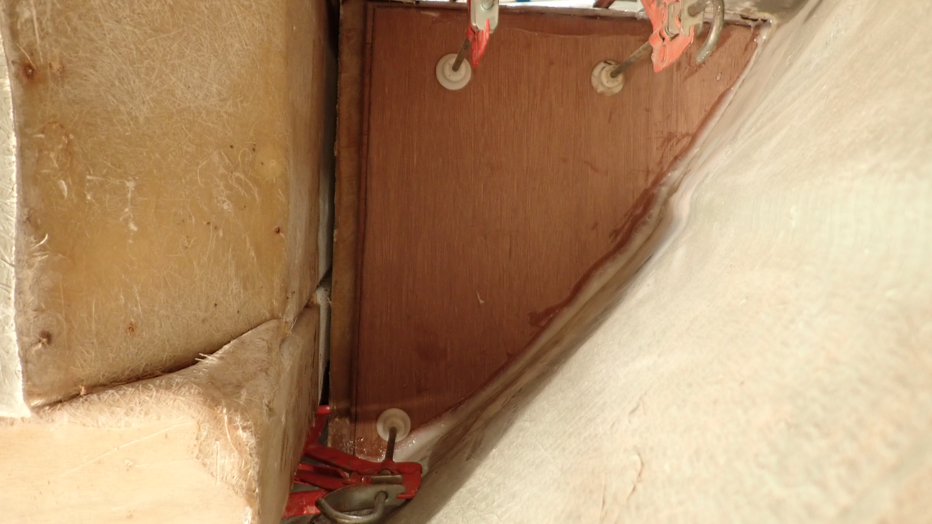
2, Once in position the panel can be clamped in place.
3, A fillet of epoxy is created round joint.
24 hours later the epoxy has set and the clamps can be removed.
The surrounding area can then be cleaned, removing al traces of stray epoxy apart from the fillet and the hull was vigorously keyed using a grinder with a flap disc ready for the knee to be laminated to the hull and then sheathed.
Grinding and sanding old grp is a horrible, messy process, generating a huge amount of fine dust that gets everywhere.
Using a sander with dust extraction is another method but it takes at least three times as long, so I take some time and sheet off the local area, don disposable overalls, mask and goggles, take a deep breath and get stuck in.
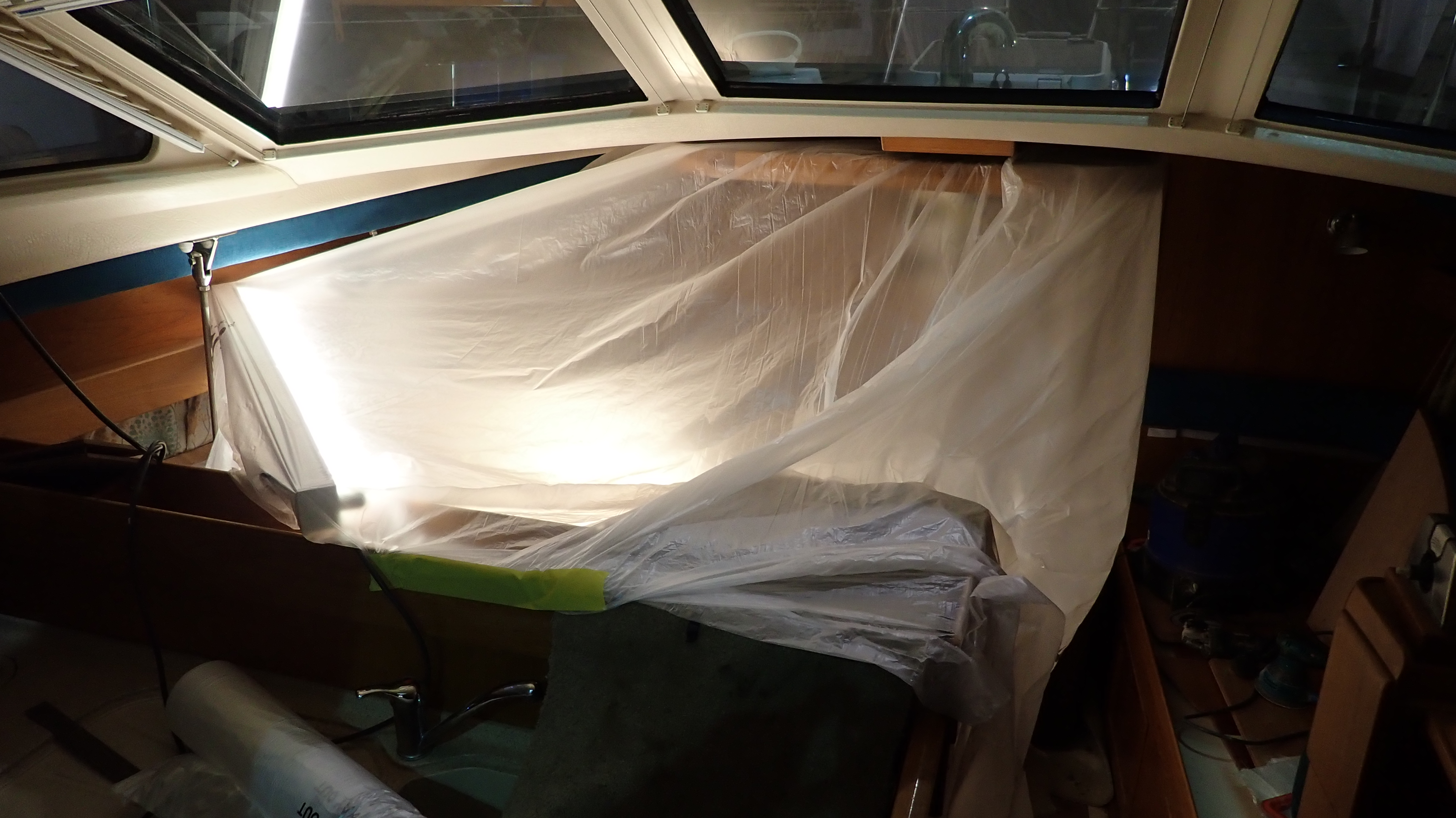
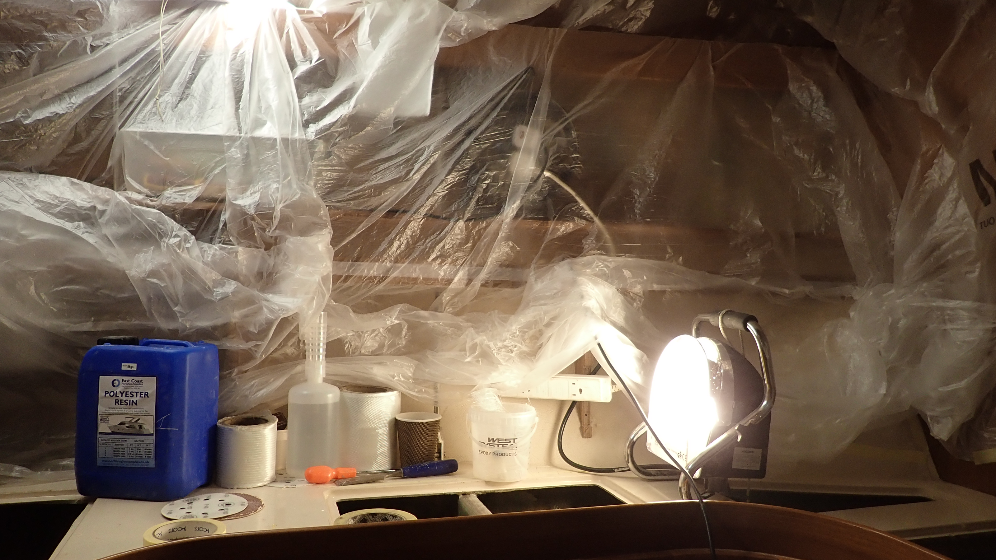
When grinding the hull the area needs to be sheeted off to prevent dust getting everywhere
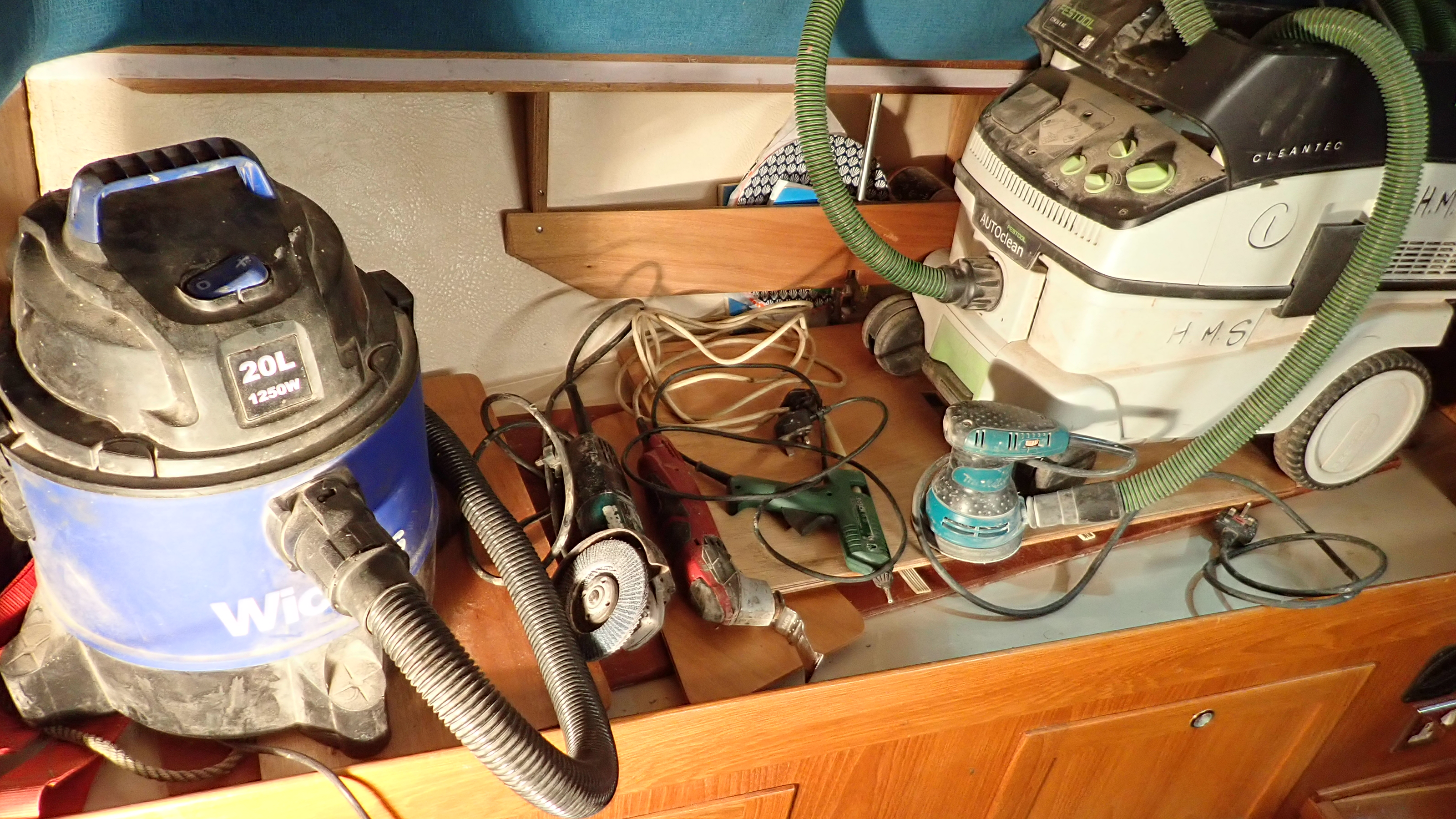
The main tools used thus far are the vacuum, 4″ grinder with 40grit flap wheel, multitool with grp gutting blade, hot glue gun, small da sander with dust extraction. oh and lots of lights, preferably florescent or led rather than heat generating halogen spots.
After 20 minutes of grinding the hull is keyed and the knee is ready for laminating.
Once the dust generating process has finished the sheeting can be removed and everything is given a through vac down to remove all traces of dust.
The glass cloth can now be cut out ready for laminating.
Do not be tempted to do this during the laminating process as what can be a messy process at the best of times can quickly turn into a nightmare.
I used a mixture of cloths.
Firstly 250g chopped strand mat.
This in my view provides a better initial key to the hull and bare wood than woven cloth.
Followed by 300g biaxial woven cloth, which smooths everything out, it falls to shape well and wets out very easily.
The main strength is provided using overlapped layers of 150mm wide 450g biaxial cloth tape.
Whilst this tape is thick and quite heavy it falls into place well and there is usually enough residual resin in the previous layers to wet it out using a roller.
I think I’ve pointed out before in earlier articles that its important not to use too much resin.
Any fool can wet out layers of chopped strand mat by flooding it with resin but this results in a weak, brittle and potentially dangerous layup.
Use the resin sparingly and work it in with the brush and roller.
It takes time and patience done correctly, around a full working day to fully laminate a knee in this case.
If it was any faster then I’d be concerned that the layup was resin rich.
Cutting the panels and organising them in sequenced piles helps you keep track during the laminating process.
1, Wet out the panel with neat catalyzed resin to avoid getting any dry areas.
2, Position the first layer of csm on the panel.
3, Using a 2″ brush you can add resin directly to the cloth.
4, Then using a consolidation roller you can wet out the cloth without using too much resin.
5, When the csm layers have been done you can add the overlapped layers of 450g tape.
6, Further layers of 450g tape are added over the csm.
These knees had 2 layers of 250g csm, 7 layers of 450g tape and two layers of 200g biaxial cloth.
7, Final two layers of 250g biaxial woven cloth to consolidate the entire layup.
8, Layup fo the forward knee followed the same process but working through a small opening made it trickier.
9, Both knees are now isolated and sealed.
With the structural knees completed, work can move onto rebuilding the locker sides and the under floor support structure.
The manufacture of the grp honeycomb panels is a straight forward process and is ideally carried out on a large bench.
Templates were made for each panel using the harboard strips and glue gun as before.
These were then transferred over to the nidaplast board, which in turn were used for patterns to cut out four layers of 250g csm for each panel.
Laying up on a bench is so much easier and much faster so that two layers were applied to one side of the nidaplast before lunch and keeping the temperature up using heat lamps the other side was laminated in the afternoon.
On the inner side of a couple of the locker sides I also applied a layer of tight woven 180g cloth which results in a very smooth surface, which is much nicer than the usual csm finish.
1, Panel templates are transferred over to the Nidaplast core, which are then cut out using a jigsaw.
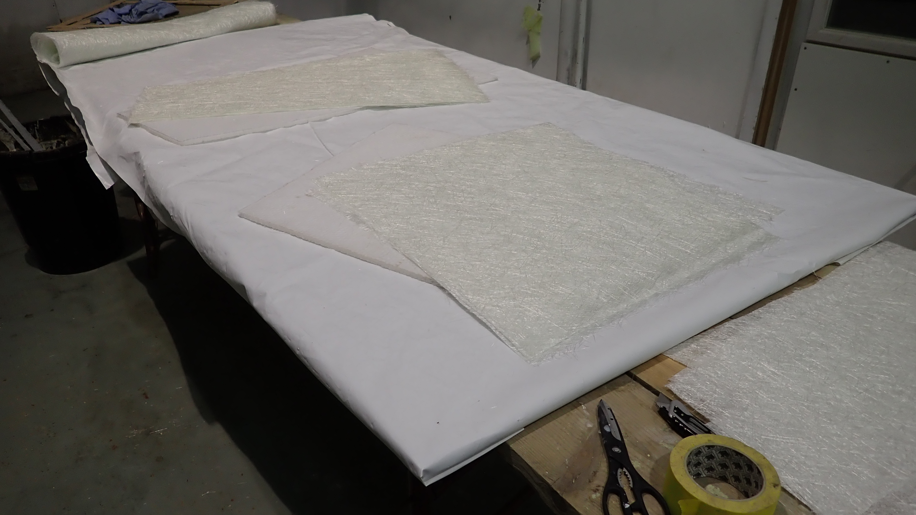
2, The Nidaplast panels are then used as patterns to cut out layers of csm.
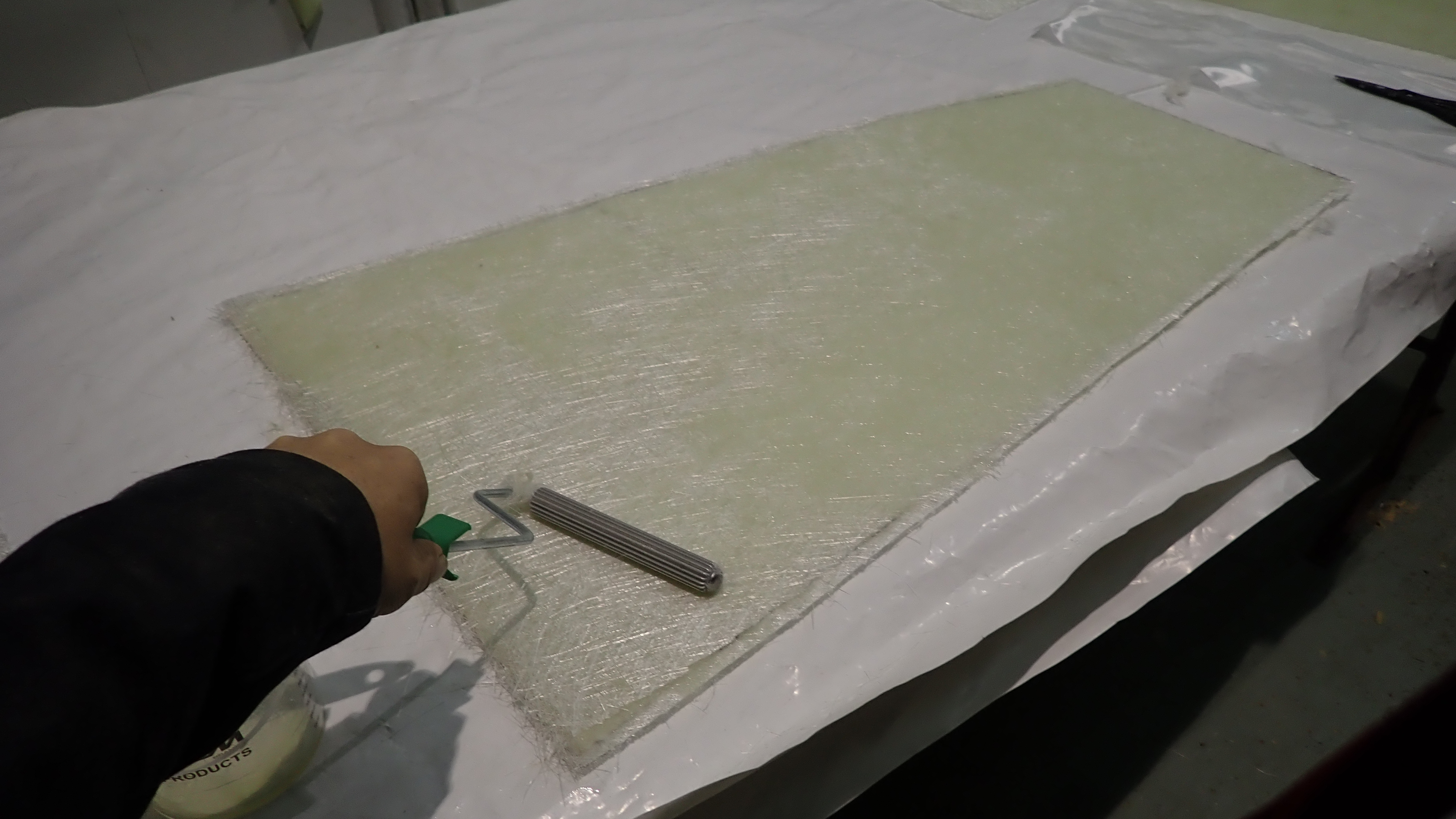
3, Each panel has two layers of 250g csm applied to each side.
4, To get a smooth finish I use a tight woven 180g cloth on top.
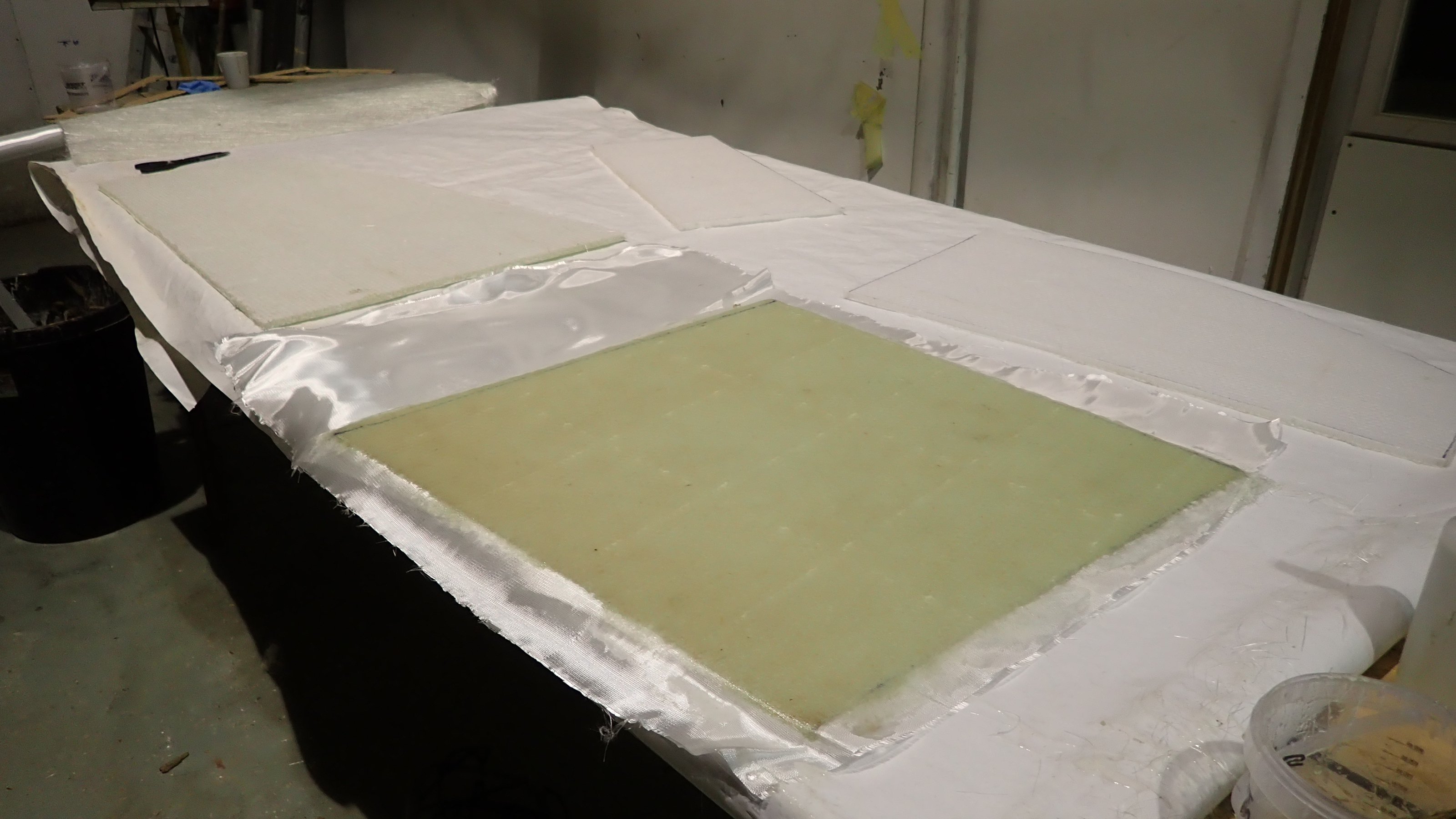
Once the honeycomb panels have been trimmed they were all dry fitted to ensure they were the correct size and to establish the order each panel would have to be laminated.
Each panel would have to be laminated around all four edges, on both sides and the only available access was through the locker tops, which resulted in a specific order.
All the panels were made using polyester resin and so I used polyester bonding paste to essentially stick the panels in place.
This bonding paste is fast acting and easy if a little messy to use.
It’s also used for most modern yachts these days to bond the deck to the hull, so its very strong but can be brittle and doesn’t allow flex.
I used four layers of 100mm wide tape for each joint.
1, Dry fitting the under floor panels to check the correct fit.
2, Each panel was glued in place using polyester bonding paste.
3, Four layers of 100mm grp tape was used on each joint on both sides.
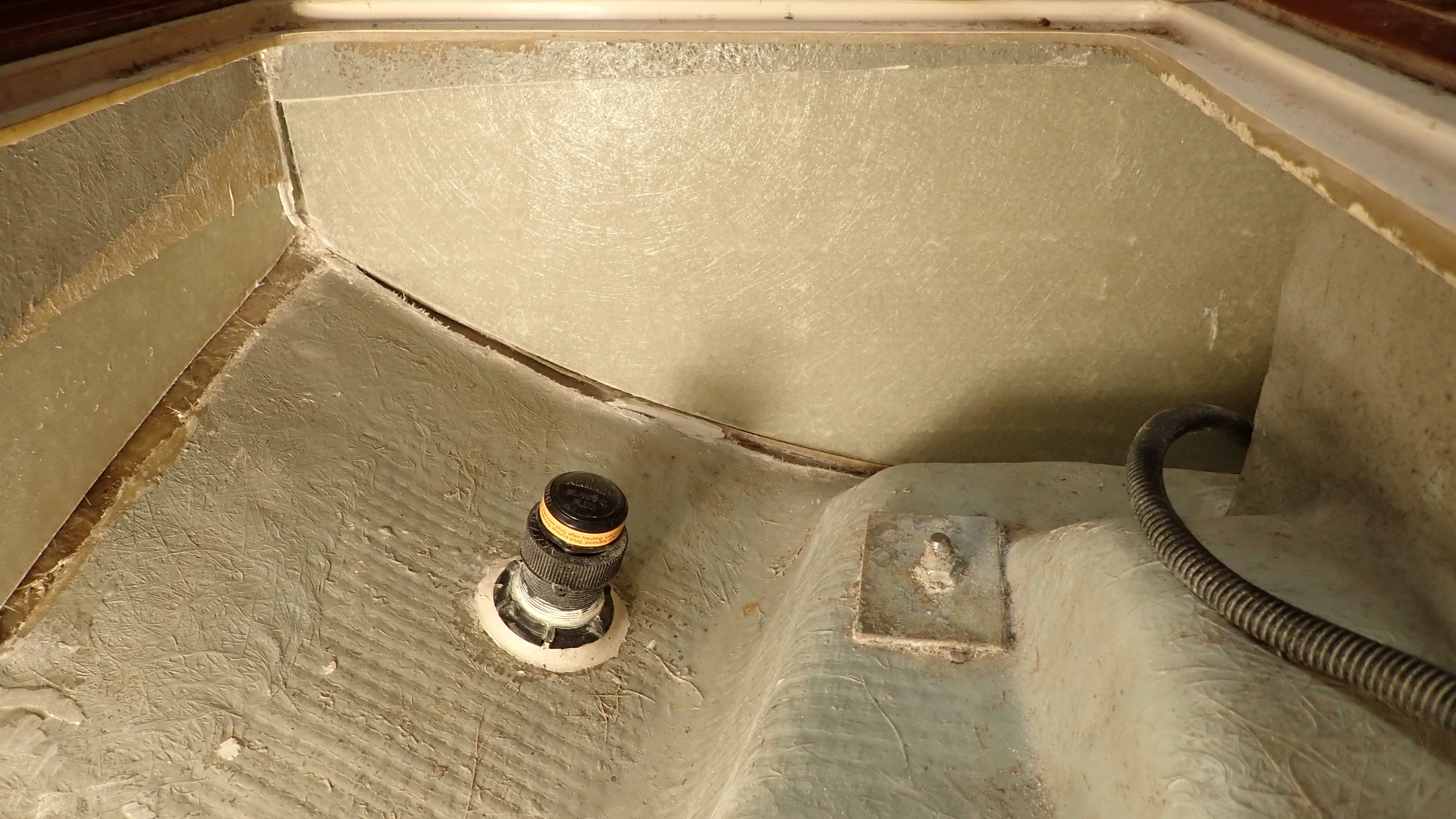
4, An access hole was created on the aft panel to give access to the water tank outlet which we had relocated.
The rebuild almost complete the next job was to give all the panels three coats of gelcoat.
The original colour was bilge grey but in practice we find white is a lot more user friendly, especially when trying to find stuff deep in the bottom of a locker at a later date.
The first two coats were standard white gelcoat and applied using a 3″ brush and the third coat had wax with styrene added so the finish would be non sticky.
24hours later the gel coat was hard enough for us to refit the modified water tank.
1, The first of three coats of white gel coat was applied to the panels and the bilge.
2, Using white gel coat makes the inside of dark spaces far more user friendly.
3, Water tank re fitted, note the new sealed inspection hatch.
4, Easy access now to the tank outlet
The chain plates were then re fitted using new 316 stainless backing plates and new M12 shouldered stainless bolts with nylock nuts.
The old chainplate bolts were machine screws and threaded all the way which is not good practice as water can draw up through the thread and rot the inside of the knee and also if there is any movement the thread can cut the hole sides like a hacksaw.
The transducer cables were re routed and all the keel bolts given a once over whilst we were there.
1, Chain plate fitted with stainless backing plates and shouldered bolts with nylock nuts.
2, Transducer cables re routed and keel bolts checked.
This job was a real eye opener to me.
Normally you get a clue or two once stepping on board on whether there is a likelihood to be any rot about.
There’s a kind of smell, an aura, a general feeling that something ain’t right.
However in this case it was a total surprise, given how immaculate and well looked after the boat appeared to be.
Still not found the fluxgate compass and I’m not at all sure how keen the customer is for me to keep looking!
All back together and looking the same as it did when I started.
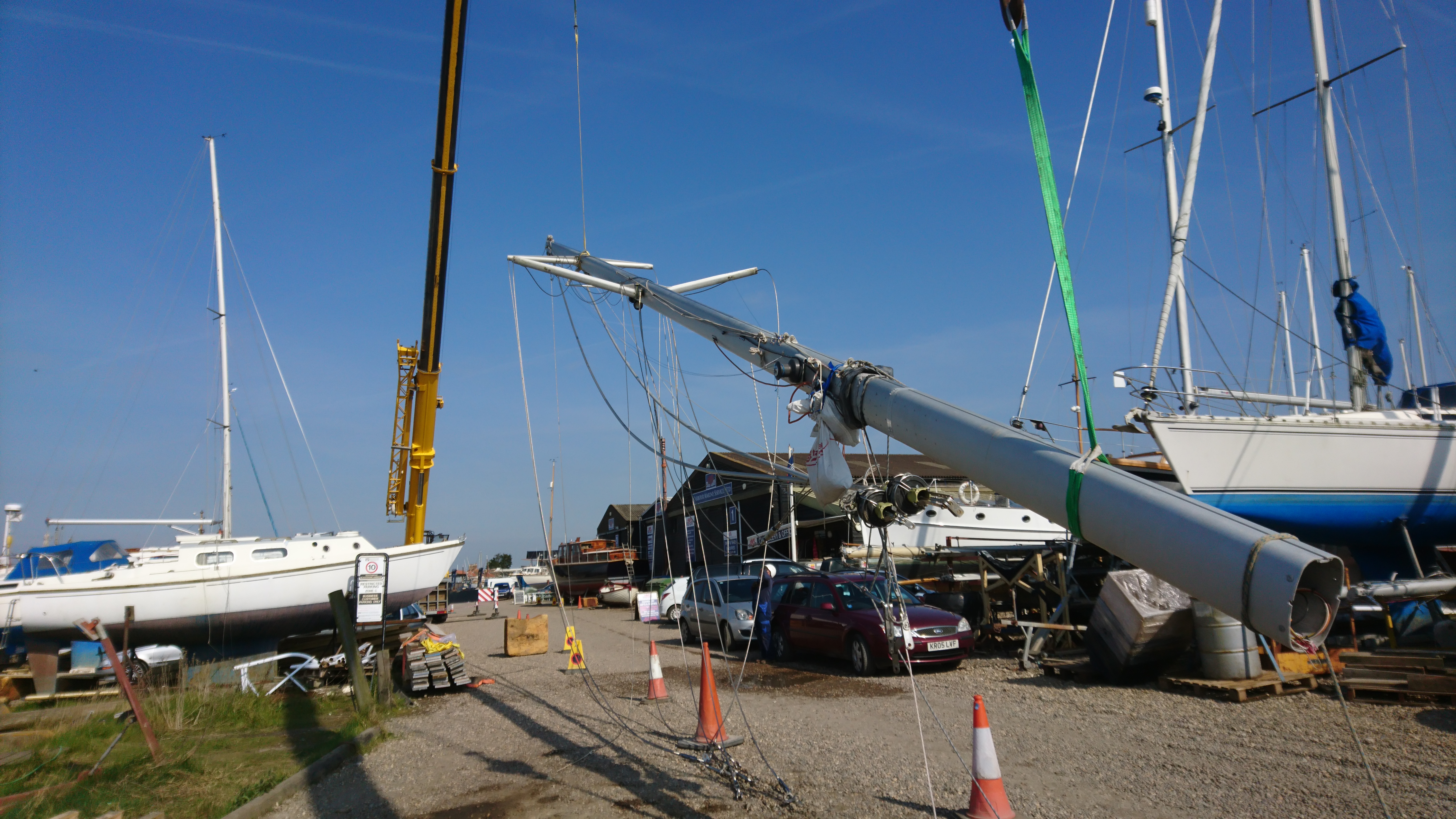
By this time of year most of the boats that are coming out for the winter are out, chocked and have been winterised.
Around half of our customers also have their rig unstepped, with the wooden masts hung up in one of our sheds and the alloy ones either on an outside rack or used as a ridge on the boat which can then be covered.
As a yard we prefer the rig to be down for the winter, especially on deep fin yacht.
When the gales start blowing in quick succession its always a worry looking at a 12m yacht standing 3m high with a big 13m wind catcher stuck on top.
The boats tend to rattle in the cradle during a blow and the cradle props need almost daily adjustment when the weather gets particularly grotty.
Couple that to hull designs that really weren’t designed to sit on dry land. Given half a chance these designs would love to wriggle free and nosedive into the dirt.
The actual process of unstepping a rig is quite easy and using our crane three of us can usually manage four or five a day.
That said a rod rigged X43 took me almost a full day to get the mast down and tidied up a few days ago.
We encourage owners to reduce their costs by removing sails, boom and pull halyards through clutches and deck organisers and pull out the locking split pins in bottle screws. Often the most complicated element is disconnecting the electrics and electronics which in many cases involves dropping the headlining, taking a number of photo’s of the connections before disconnection. All of which at least doubles the time needed to drop the rig, which at £30/hr yard cost can add up to a tidy sum.
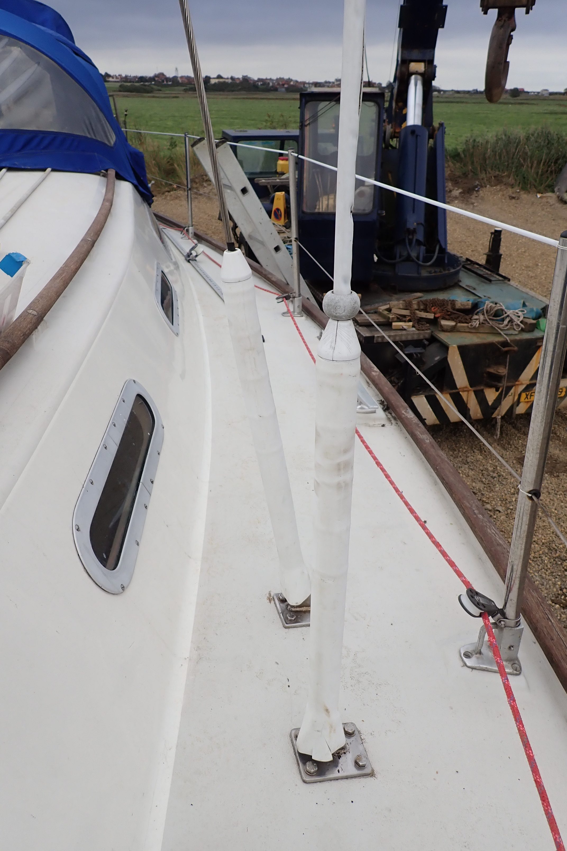
With the rig down its an ideal opportunity to check the rigging, anchors points, spreaders, track and masthead sheaves, fittings and the like.
In my experience you won’t find much wrong with the wires, the trouble always tends to be at the terminals at either end or in the case of the cap shrouds sometimes at the spreader ends.
That is for those who have not fitted plastic shroud and/or bottle screw covers and to some extent plastic spreader end caps.
For those who insist in fitting these satanic accessories the life of the wires can be significantly reduced.
Due to the spiral nature of the wire, water, salt, crud and grime will wind its way inside the plastic cover. The wire gets coated with grime effectively sealing the inner core wires from oxygen which leads to a breakdown in the stainless steel surface protection which then leads to corrosion and failure.
The same applies to pvc coated guard wires which quite rightly have been banned by those who wish to sail the arc.
If you have plastic coated guard wires, that are there to save your life, throw them away and replace with plain stainless or at the very least strip away the plastic coating.
Just remember that Stainless Steel requires oxygen to maintain its protection qualities and anything that reduces this is an avoidable risk.
Another prime candidate for corrosion is at the spreader ends.
Most spreaders are aluminium and these often have a stainless pinch bolt clamping the alloy end piece onto the stainless wire.
Alloy and Stainless are not great together at the best of times so covering them with a plastic cap and taping them up increases the likely hood of corrosion. Yes it might save a little bit of wear on the rare occasions that you over sheet the genoa or ease the mainsail so far out that it touches the spreader end. You could try and isolate the stainless from the aluminium by using Duralac or similar coating but I’d rather make sure there were no sharp sticky-out bits and add a small wear patch on the sails in these areas, after checking if its actually really needed.
Insurance companies seem to vary their requirements for a standing rigging change.
Some say 10 years, some 8 years and some also specify a maximum sailing distance like 20,000 sailing miles.
The plain fact is that apart from spotting obvious wire damage like kinks, broken strands and cracks in terminals, its pretty much impossible to check the condition of the wire core or the internal section of a swaged terminal, which has largely led to the age limit being imposed.
I have my own rule of thumb which applies only if the rig looks in good condition.
8 years for terminals and hence wires, 12 years for bottle-screws and 16 years for chain-plates.
Stripping the mast of the old standing rigging generally only takes a few minutes, though dismantling of spreader end clamps can require wd40, patience and sometimes a bit of localised heat.
Invariably the time consuming element is stripping out the forestay from a furler spar.
Depending on the make of the furler this can take an hour or so and run the risk of ball bearings escaping in all directions. Early Furlex systems can be a pain in this respect. Pro furl systems are much easier and Harken by far the easiest.
Many of the older systems like Hood and Rotostay are no longer in production and these and others used their own terminals which are used in the lower drum bearing.
So care is needed when dismantling so that you can reuse this part and always remembering to run a mousing wire up through the spar so that the new wire can be pulled through later.
In some instances we will have to get a new terminal machined up if the old furler is to be kept.
We use Sta-lok for our wires and terminals.
We’ve used other, cheaper suppliers in the past and have regretted it 18months or so later, usually due to discoloration of the wire or chrome flaking off the bottle screws.
Sta-lok inform me that they only source their wire from KOS Wires and that the wire finishing process is simply superior to other suppliers.
I usually just coil up the wire, label it and send it off to Sta-lok where they simply reproduce using new wire and swage ends.
Normally we will also specify Chrome Bronze bottle screws as opposed to stainless steel as Stainless does tend to stiffen up making it difficult to adjust under load and can run the risk of cold welding which is not uncommon.
I would say a fair percentage of owners don’t actuality realise their bottle screws are chromed bronze, most believing that they are stainless.
Recently we changed the standing rigging on an Oyster 435 and we used the impressive new Stalok Supajust turnbuckles which have a polished 316 Stainless body with threaded bronze inserts permanently fixed in each end.
When I make up a rigging for a new mast I tend to use the Sta-lok self fit terminals at both ends and cut the wire myself from our stock.
Sta-lok terminals are very good quality, I’ve seen their impressive manufacturing facility and that gives me confidence.
They are also easy to fit once you get the hang of it and tests show that they are stronger than conventional swage and certainly stronger than the wire itself.
The fittings are more expensive than standard swage fittings but they are reusable (with a new wedge) making the next rig change much cheaper due to only requiring new wire.
Invariably you will need to use a self fit terminal for the forestay as you won’t get a swage terminal through the furler spar.
With the rig down its also time to inspect all the terminal points, spreader brackets, masthead fittings and other equipment mounts such as radar reflectors, radar, antennas and the like.
In a lot of cases the mounts at the hounds, masthead and the numerous other brackets will be using 316 stainless fittings and bolts. You really need to ensure there is adequate isolation using Duralac or another isolator, otherwise these dissimilar metals will lead to corrosion on an aluminum mast.
Check the condition of the electrical cables and light fittings.
Do not be tempted to swap the old fashioned masthead light bulbs for led’s unless the lens has been specifically designed for them.
You could find you invalidate your insurance.
Another area that is often overlooked are the halyard sheaves.
As standard they tend to be plain bearing nylon, bronze or aluminum turning on a stainless pin.
The main halyard sheave is subjected to the most wear and its well worth swapping the sheaves about to take this into account.
One small but significant upgrade is to swap the main halyard sheave out for a ball bearing variant from Harken, Ronstan, Garhauer or similar.
The difference almost always pleasantly surprises the owner as suddenly they can hoist the mainsail so much easier, often negating the use of a winch, with the only downside being that the sail drops a lot faster which can catch you out for the first few drops.
Another modification we carry out on a regular basis is to convert the main halyard into a 2:1 system.
This is especially useful for those of us who are knocking on a bit and starting to lose power in our shoulders when hauling up the main.
Essentially one end of the halyard is terminated at the top of the mast.
It passes from there through a high load block attached to the head of the sail and then back to to the top of the mast through a ball bearing sheave and down.
The downside is you have twice the length of halyard to deal with at the bottom but the up side is you are suddenly twice as strong.
It also has the benefit of allowing you to drop down to a smaller rope size, reducing friction still further.
Stepping the mast is really just a reverse of unstepping though keel stepped masts can be awkward on bigger boats as there is often very little space, the crane driver can’t see below decks and there is very likely to be lots of shiny varnished wood in the vicinity.
Oh and don’t forget to thread the mast through the saloon table on the keel stepped Victoria 38, as I managed to do, oops.
When preparing to drop the bigger rigs we usually pop up and remove the wind transducer and antennas to avoid them being damaged by the crane.
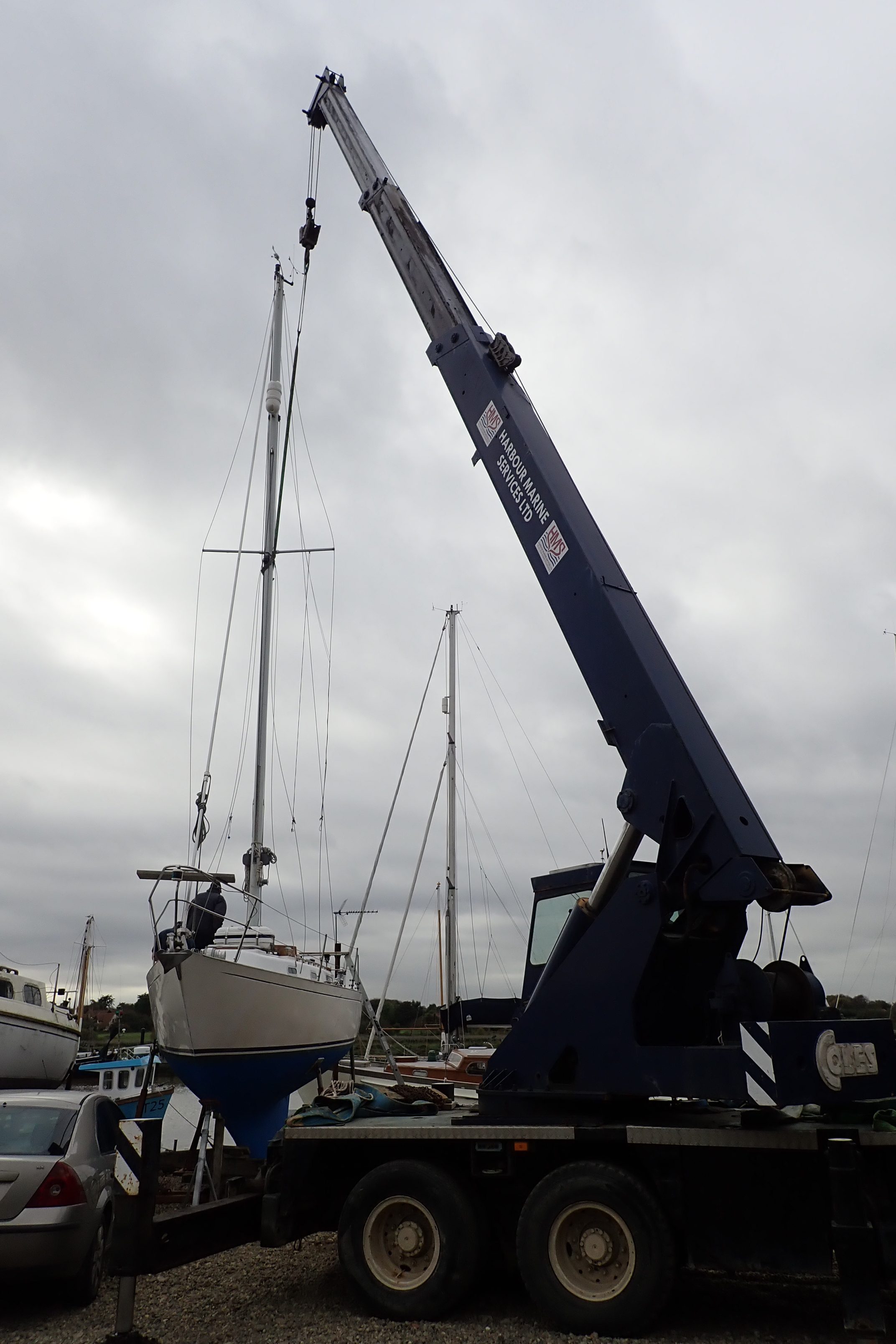
Most rigs can be craned using a strop just below the spreaders.
Twin or triple spreader rigs will usually mean we need to sling higher than the lower spreaders.
We sometimes have to draft in a bigger crane for masts over 70ft.
Shroud and bottle screw covers look nice, but…
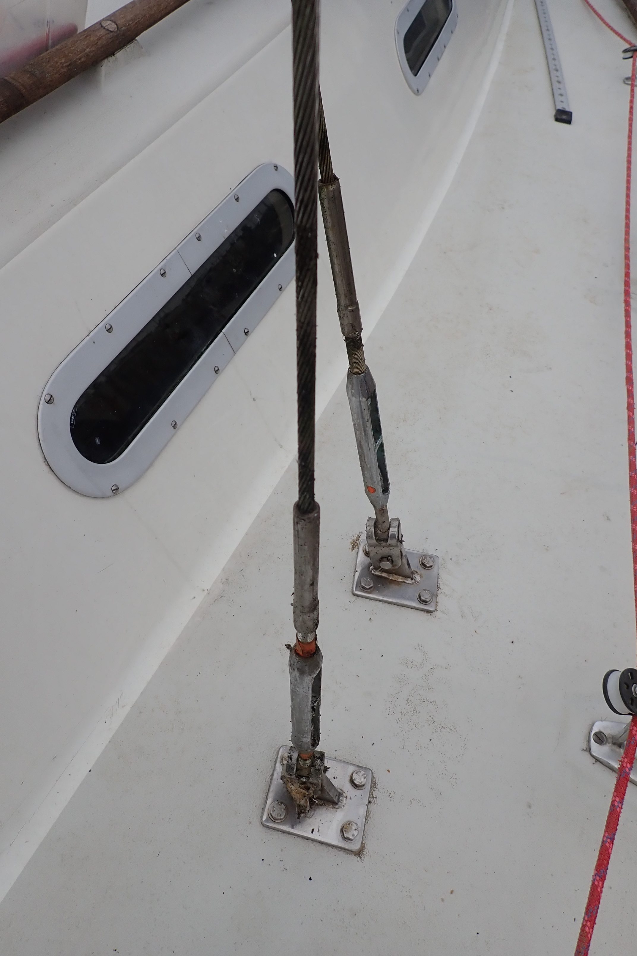
The normally shiny stainless wire will be dirty, grimy and possibly corroded.
The bottle screws will be stiff to adjust with the chrome peeling off.
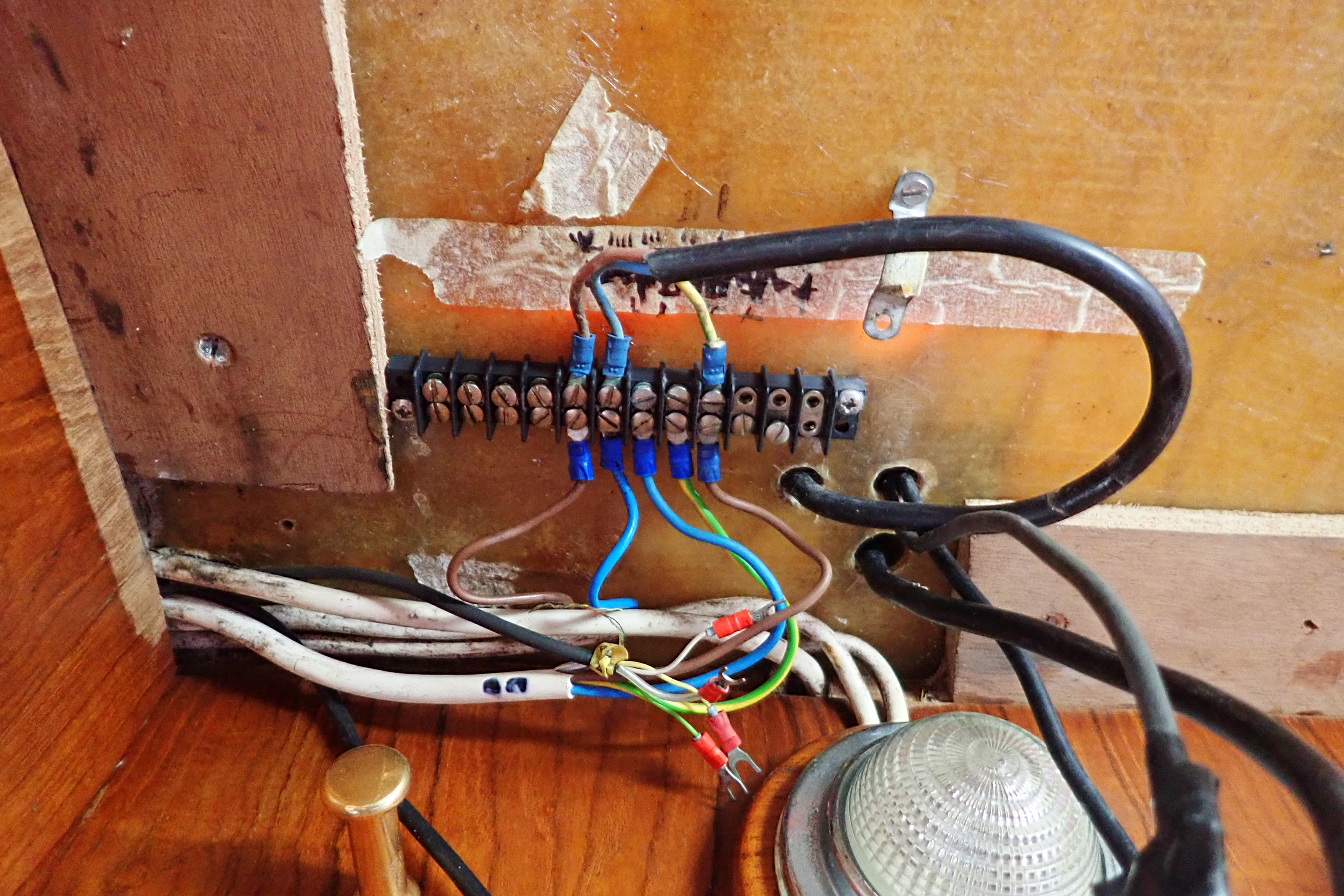
We take photos of the mast wiring before un-stepping the mast.
Once the wiring has been disconnected and the halyards and shrouds tidied the mast can be removed.
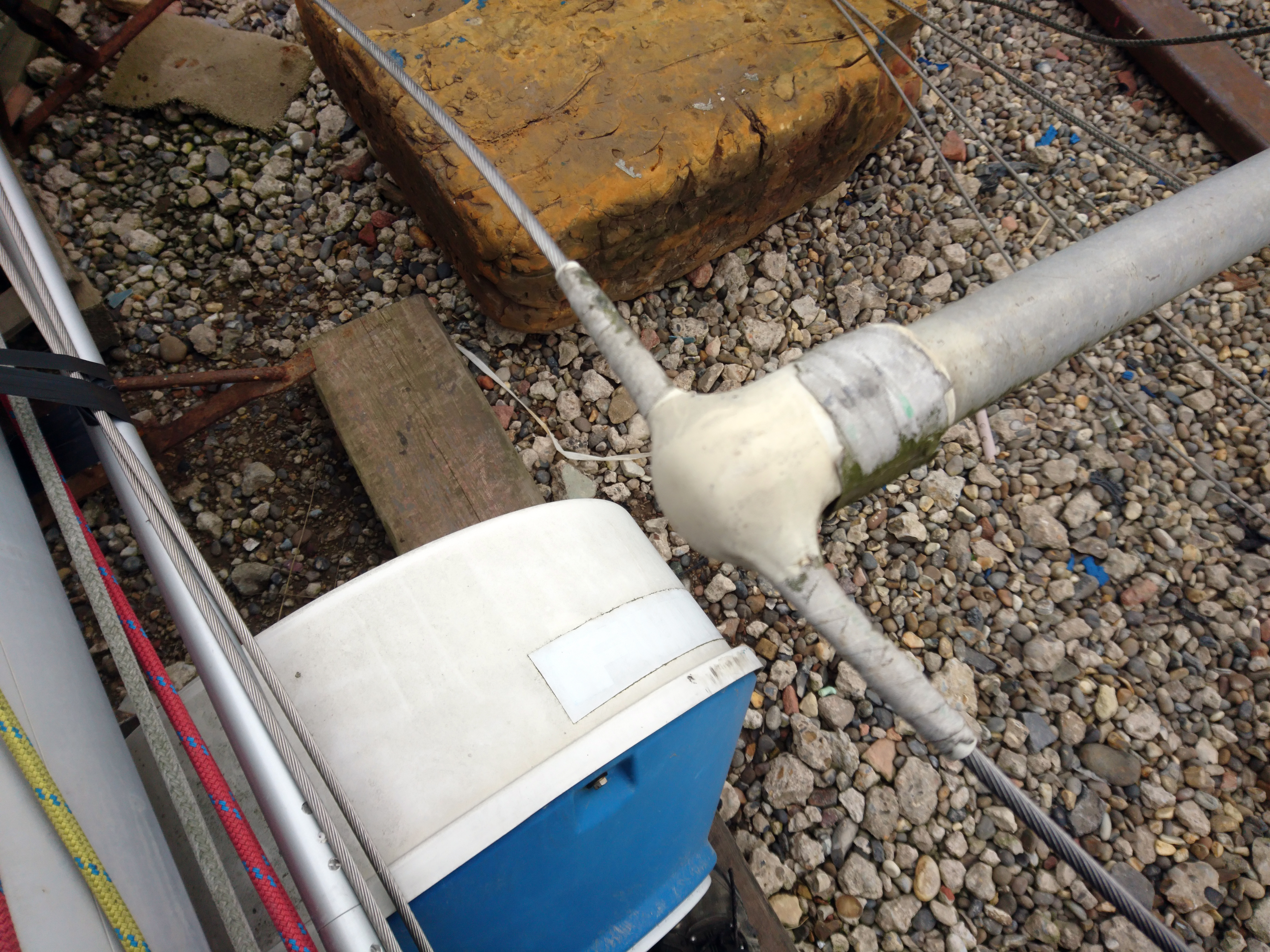
Spreader end caps look innocent and might seem like a good idea….
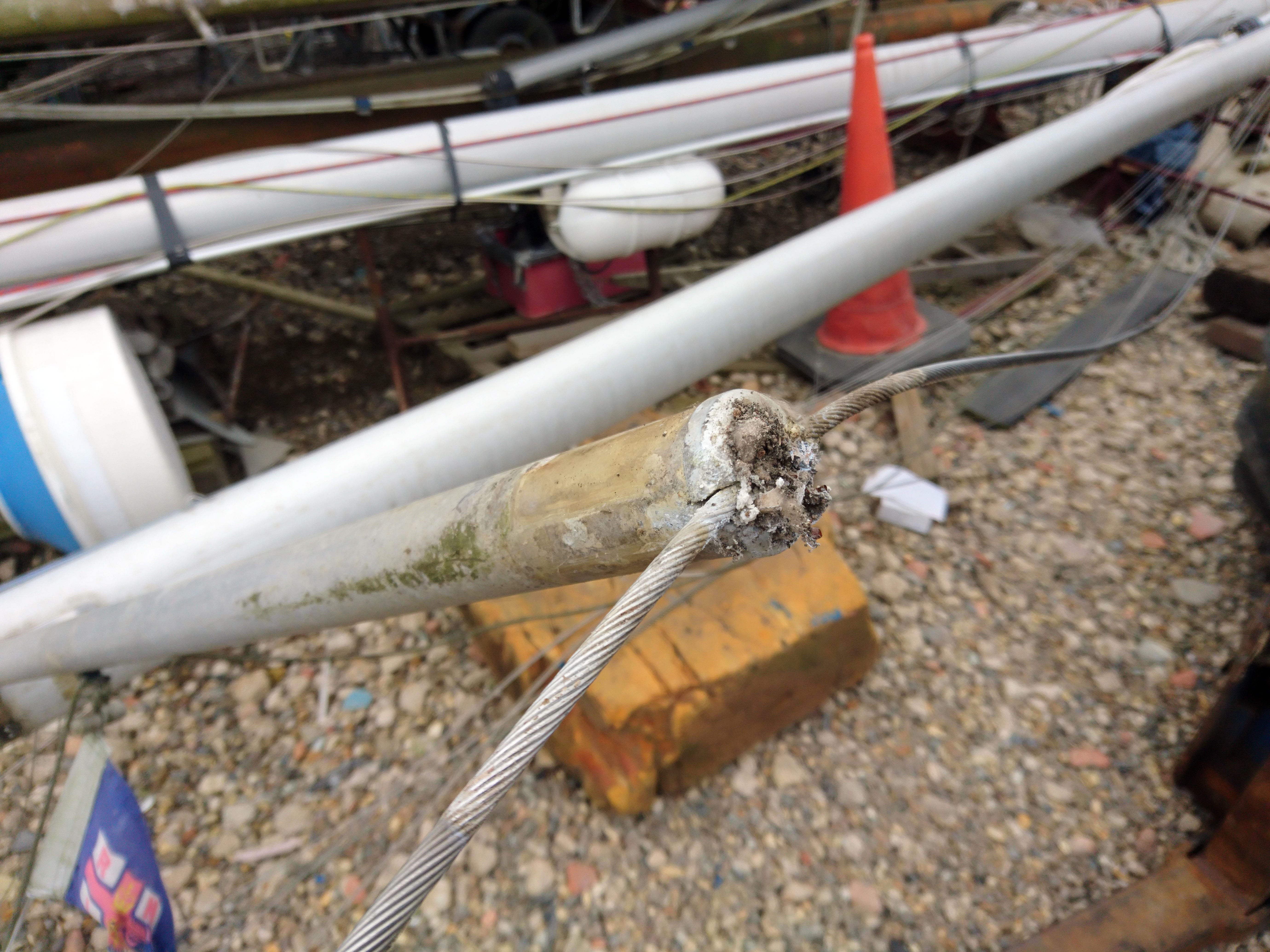
Removal of the spreader cap often reveals the horror beneath.
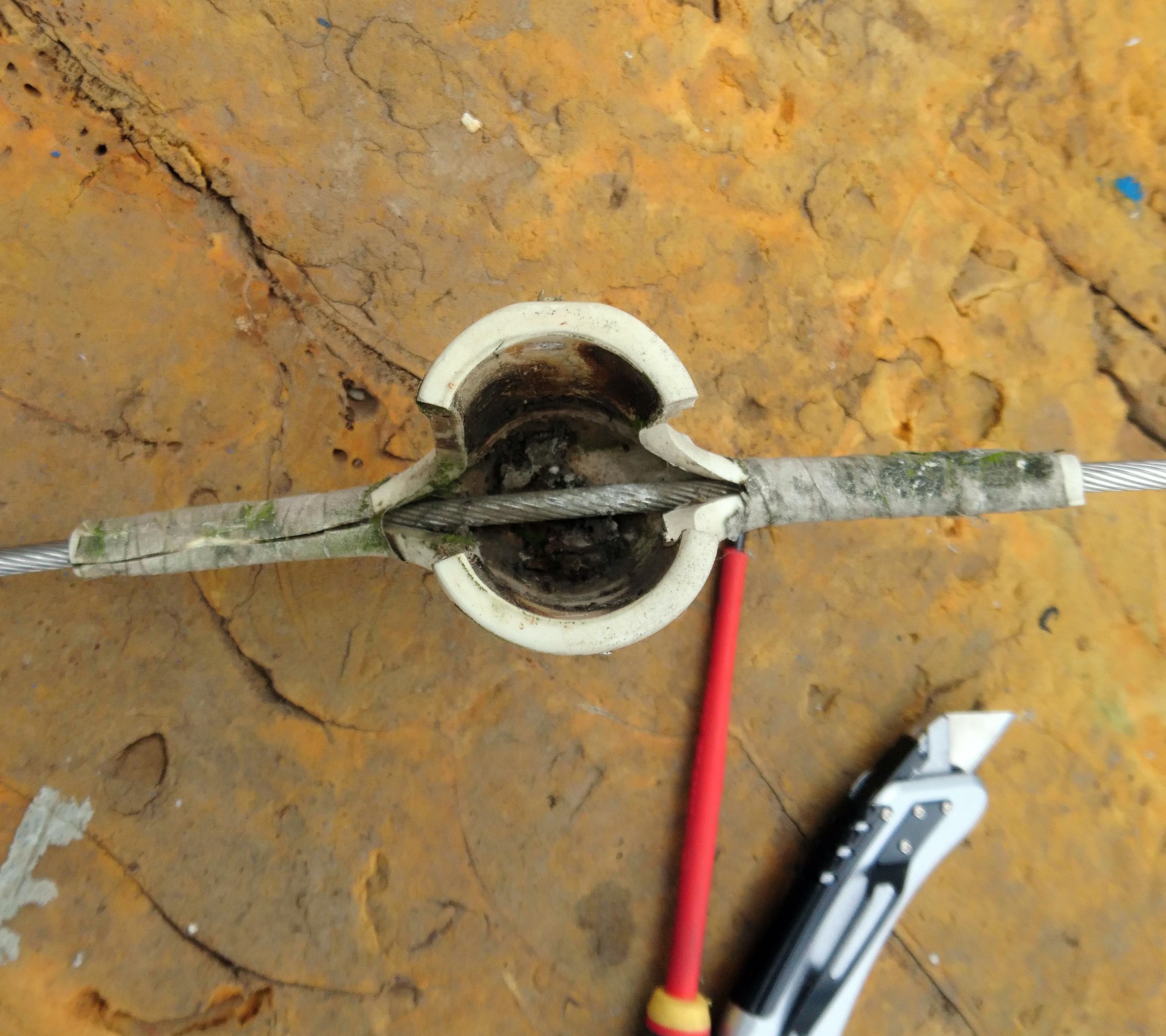
Either get used to removing and cleaning the end caps on a regular basis or find another way.
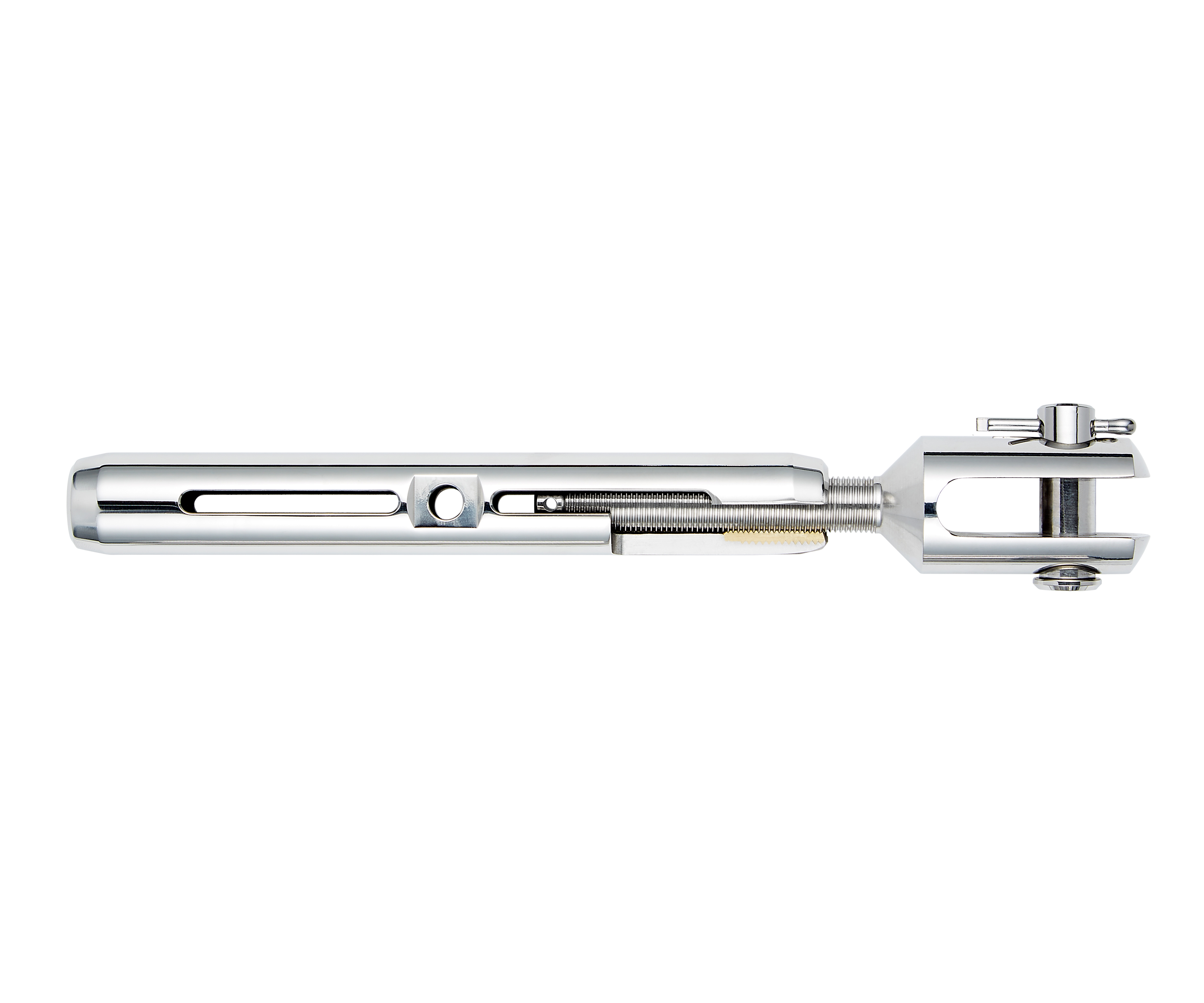
The Stalok Supajust uses a stainless body with bronze threaded inserts avoiding the dreaded cold weld seize.
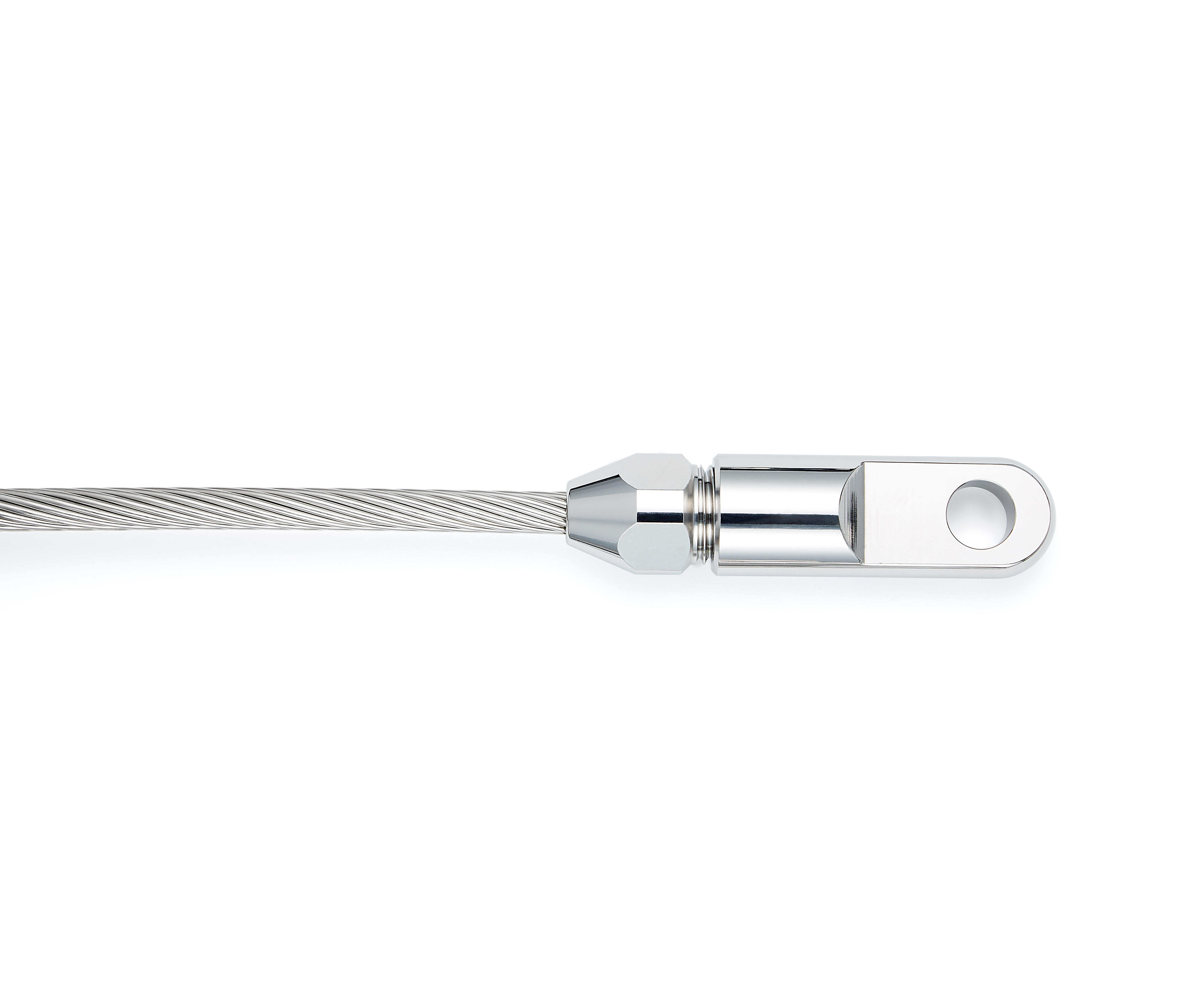
These self fit terminals from Stalok are easy to fit but very strong and do allow you to open them up and inspect for corrosion or reuse them on new wire.
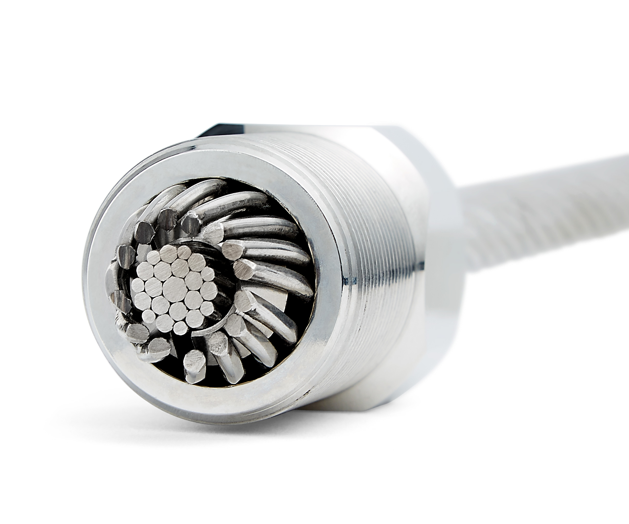
With the Stalok fitting opened you can inspect the condition of the wire.
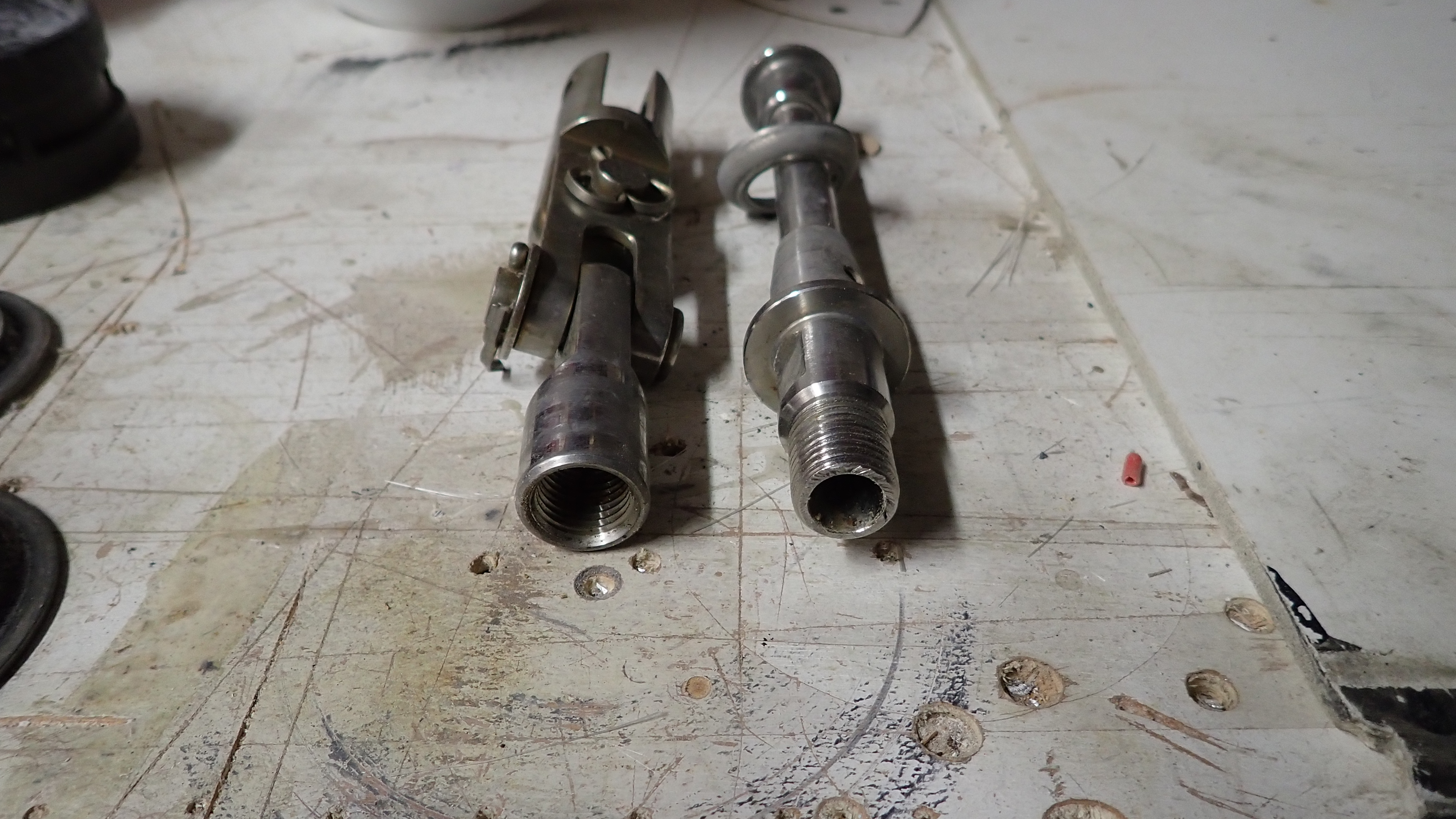
With a Furlex Furler, these are the bits you need to get at.
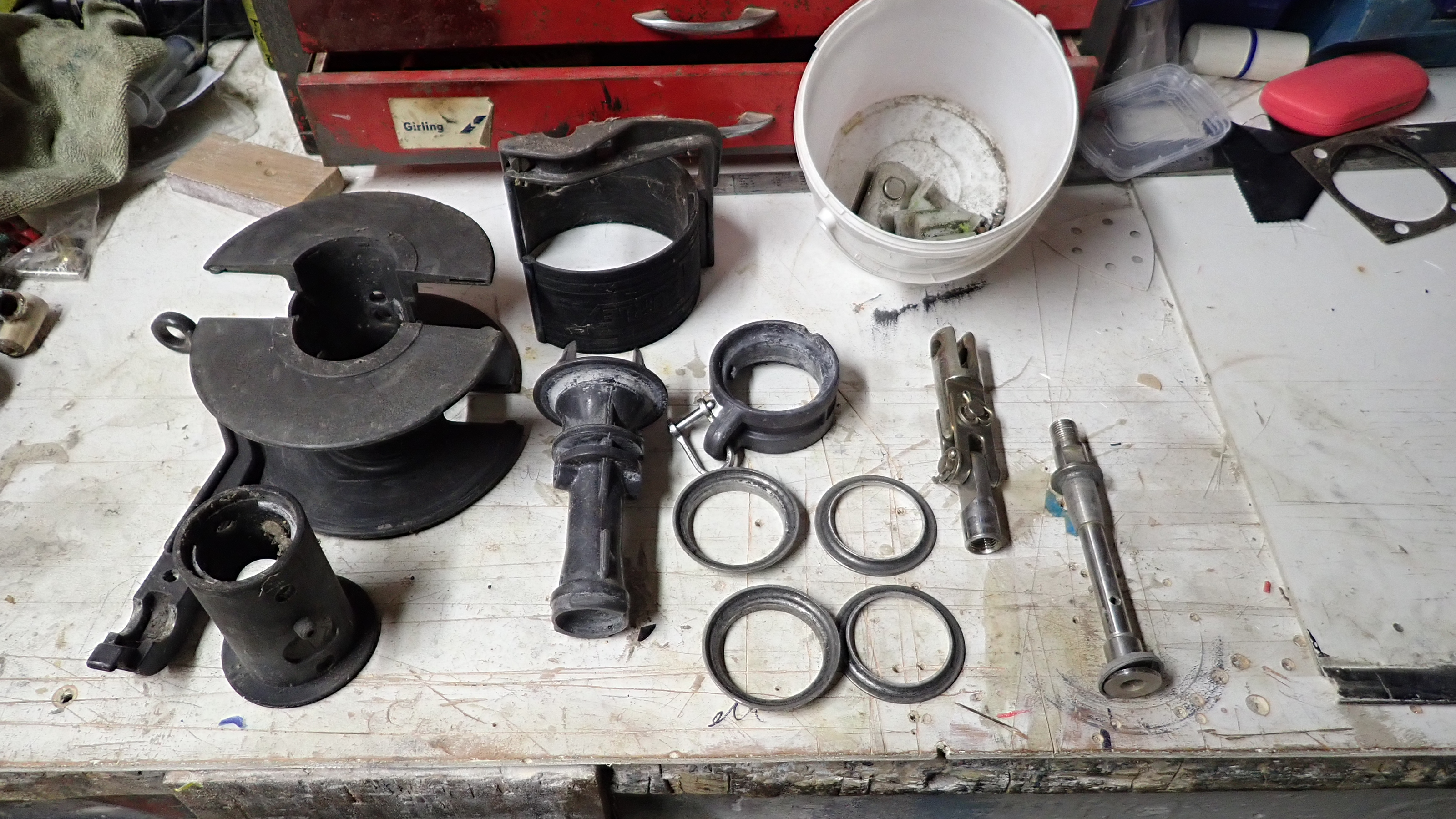
However to get to the reusable terminal fitting you need to largely dismantle the entire furler assembly or at least so far that you may as well do it anyway and then you can inspect the races and replace the ball bearings.
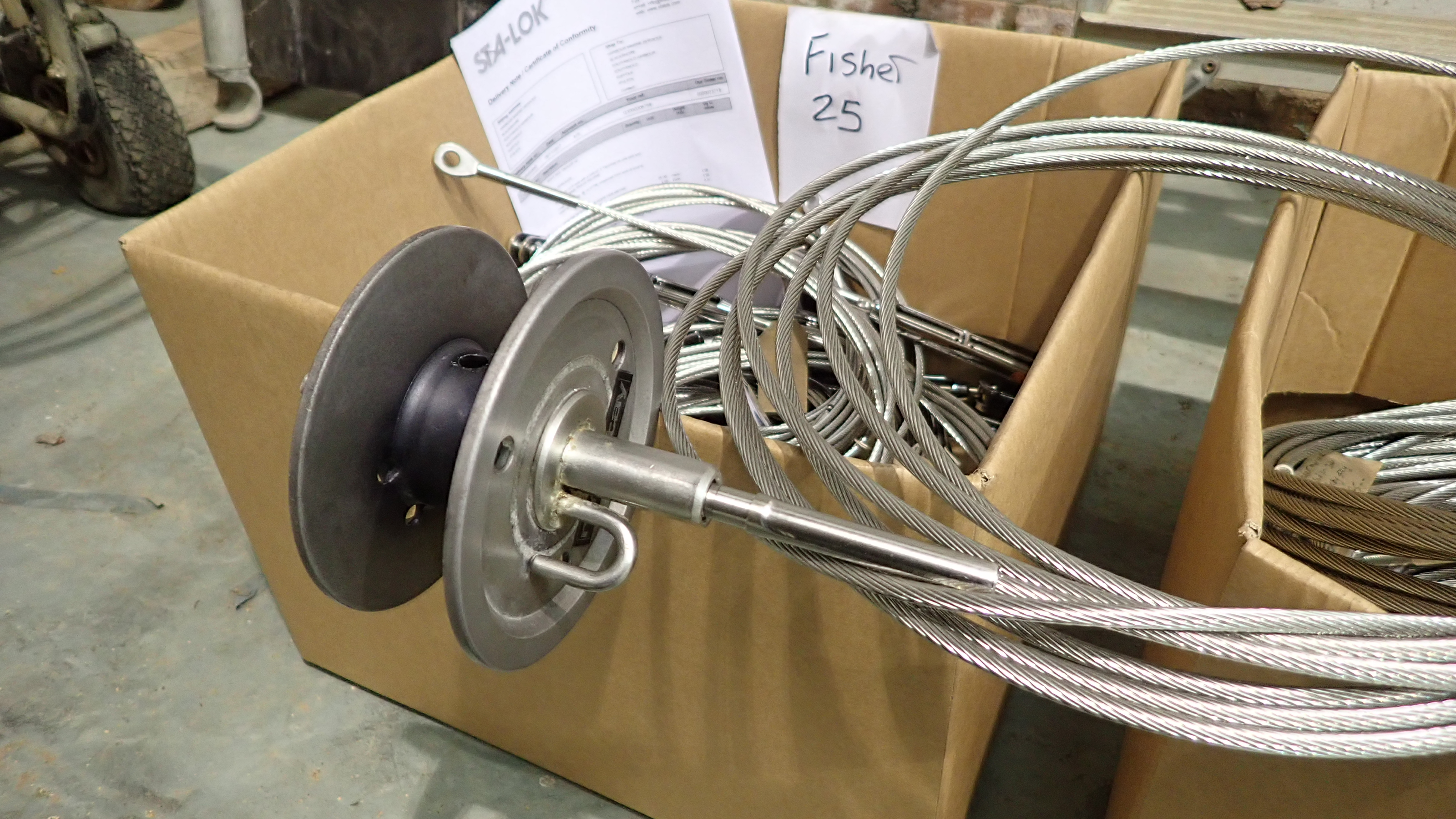
The new wires for a Fisher 25 ready for fitting.
In this case the lower terminal that accepts the old Rotostay drum had to be specially machined to fit.
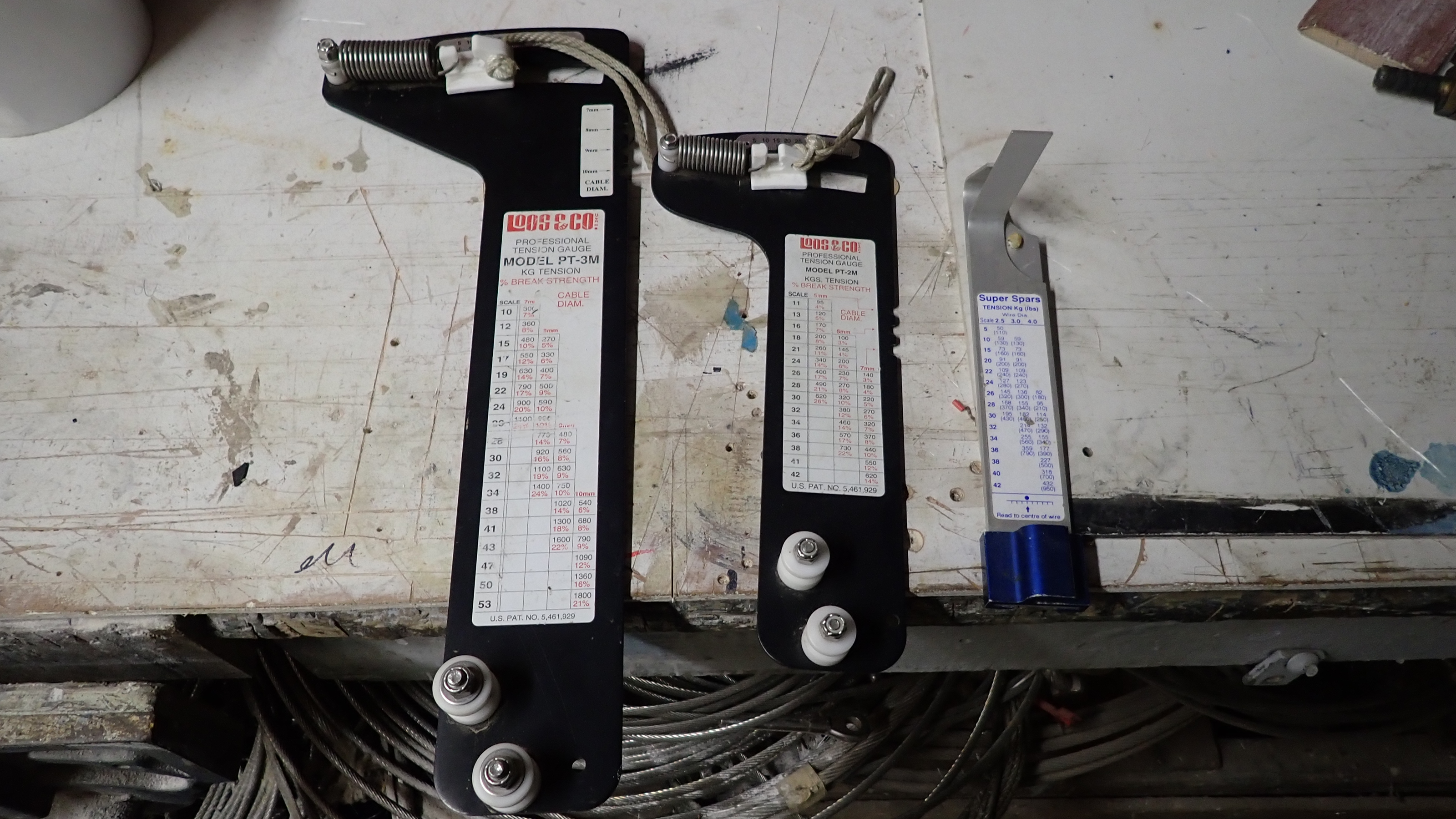
When the rig is stepped again you will need the right size tension gauge to set the rig up correctly.
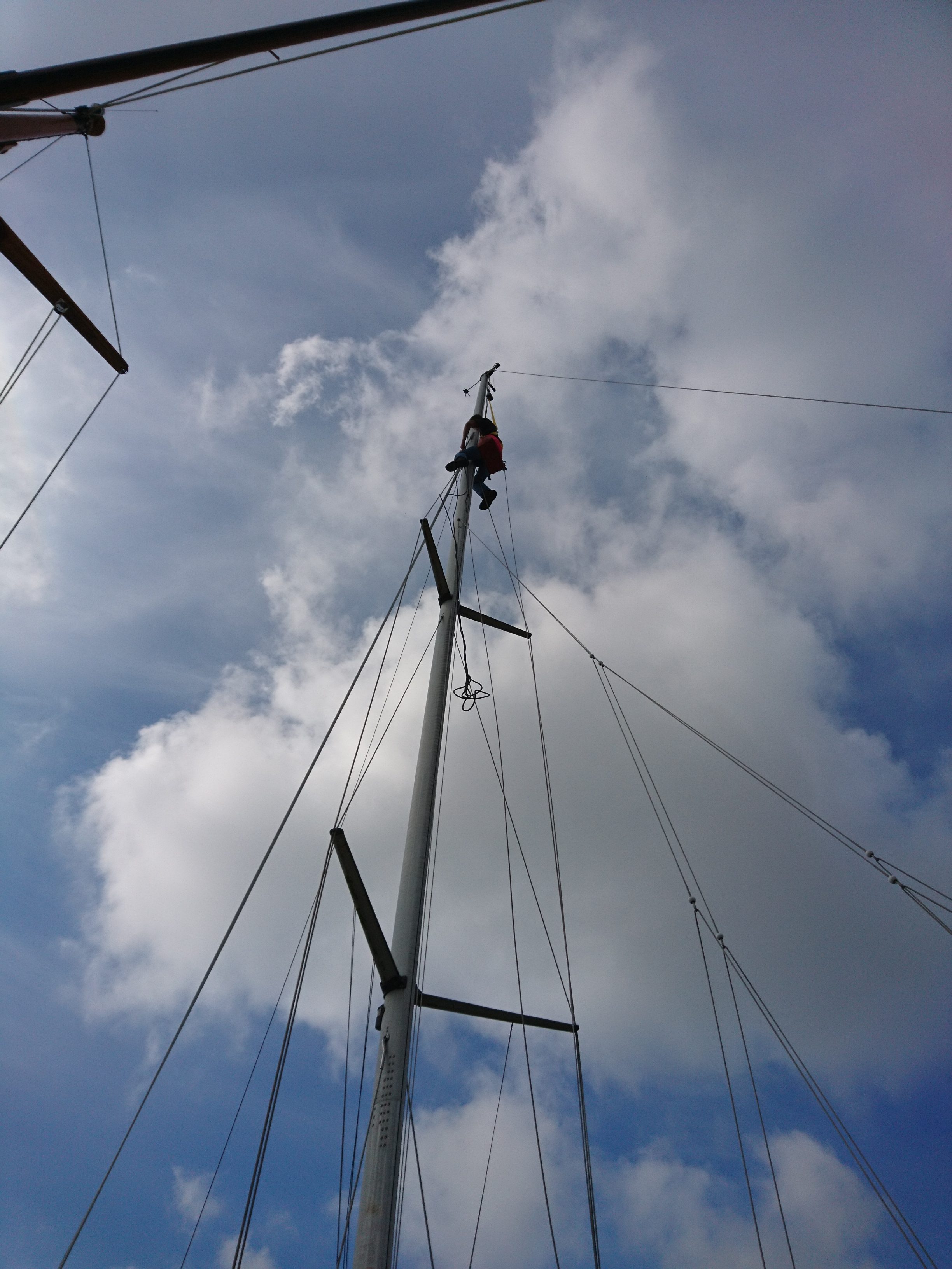
Occasionally even though we spend a fair time on the ground getting all the lines organised, we still have to run up the mast to re route an errant halyard that mysteriously got the wrong side of the spreaders during the hoist.
A significant proportion of our work at the yard comes to us via insurance companies and usually as a result of some unfortunate accident.
In this particular case a Southerly 115 was clobbered whilst sitting on her mooring by 40′ yacht who were obviously having a few handling issues.
Southerly’s of this era are pretty heavily built, so to have an impact where the teak rubbing strake was shattered, hull and deck punctured and the internal bulkhead pushed to port, shearing the headlining screws, separating the grp lining from the coach roof and companionway, it must have been a hell of a bang.
In point of fact the hull was fine as the hull deck joint is under the teak rubbing strake, some 20″ below the side deck level.
The vertical section of deck is around 10mm thick and the horizontal is made up of a 5mm inner layer, 12mm plywood as a core and another 8mm of glass and gelcoat on top.
There is also a grp and gelcoated toe rail which was integral to the deck, having been molded when the boat was built.
Grp is strong, flexible and can take a lot of abuse without much visible evidence.
Gelcoat however is not very flexible and will crack and craze very easily after an impact.
So if you can see the damage is right down to the laminate you just know the gelcoat damage will be far worse and will possibly spread over time.
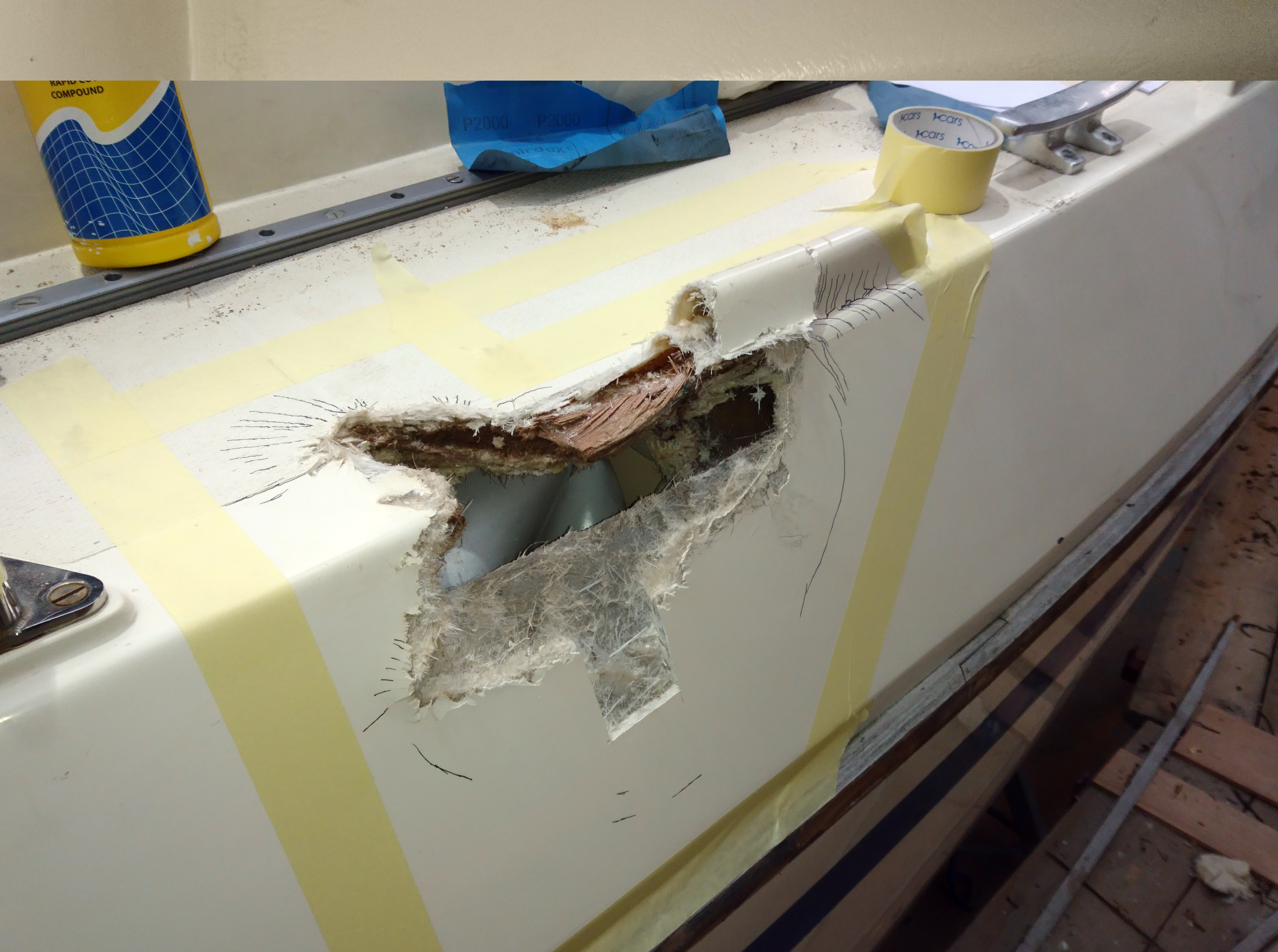
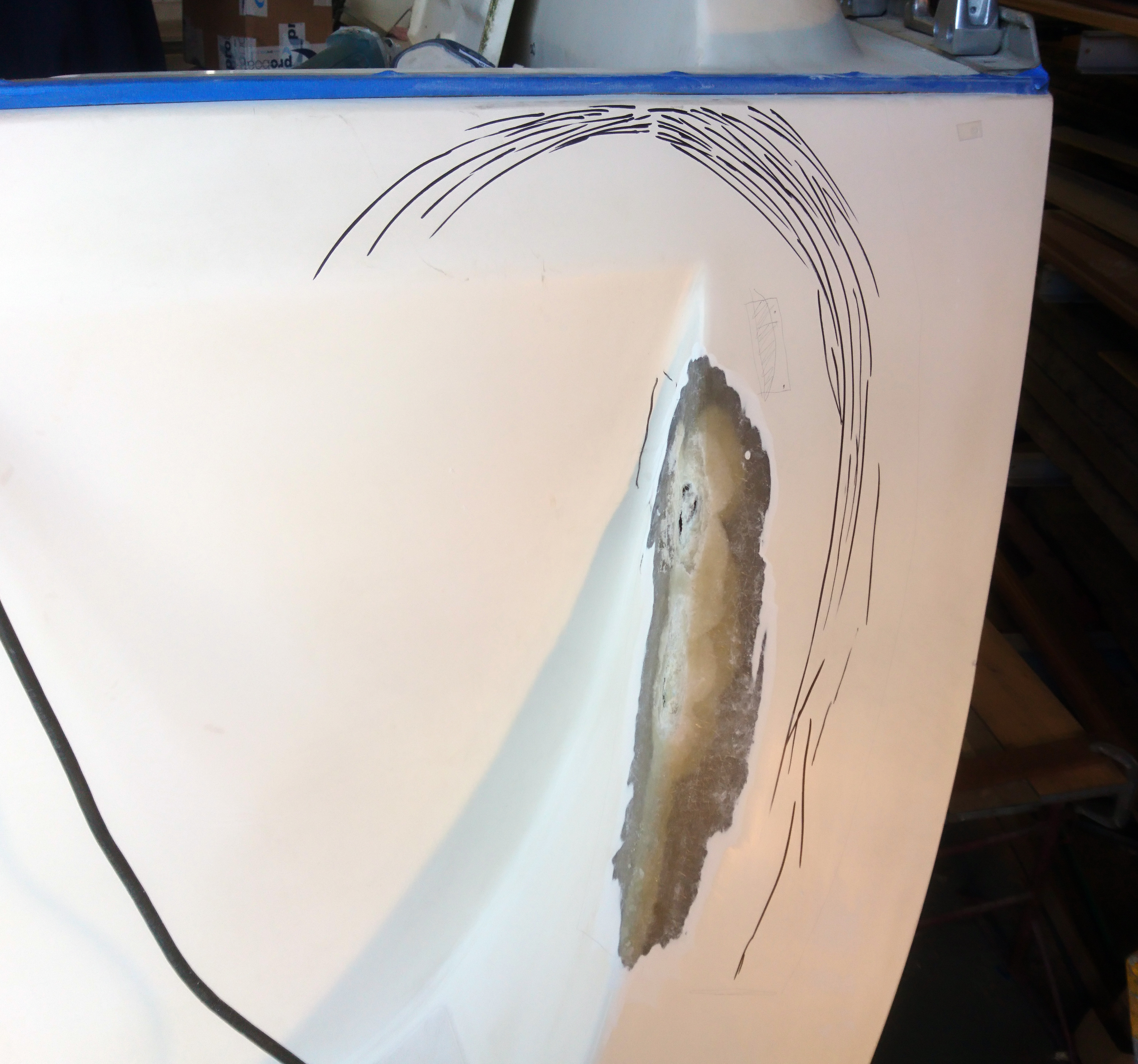
The damage included a significant wedge taken out of the deck.
The puncture went through the hull and deck and can clearly be seen in the heads.
A common misconception is that those nasty little cracks and crazes in the gel coat do not emanate from the surface down, in fact the opposite is usually true.
An impact makes the grp flex, the gelcoat attached to it can’t flex as much, so it cracks from the laminate outwards.
So the only way of successfully repairing gel cracks is to grind all the way back to the laminate and re gel.
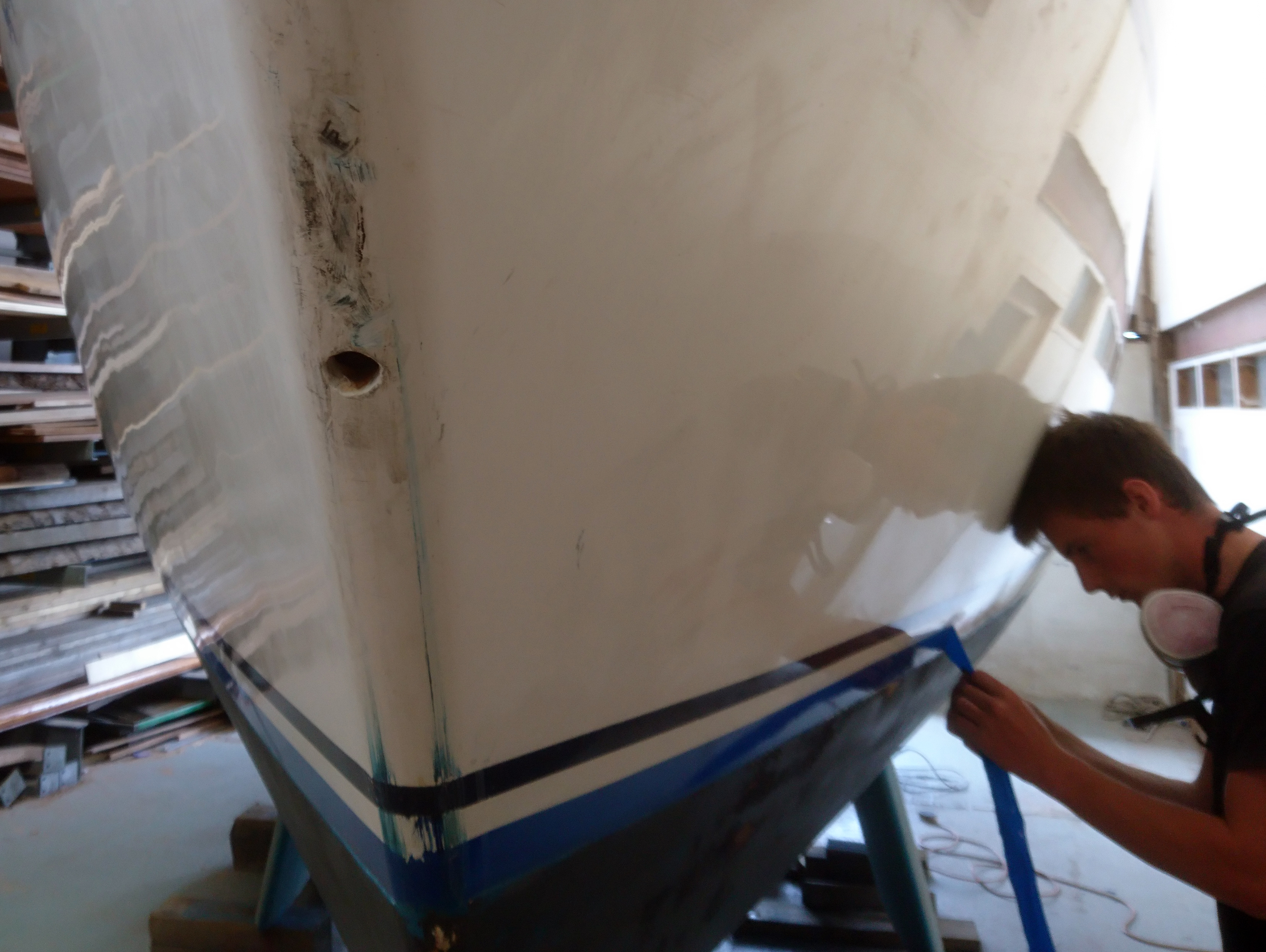
In this case one of the first jobs was to trace all the cracks and crazing caused be the collision.
I employ young eyes for this task as even with my reading glasses on it’s easy to miss tracking a crack a fraction of a millimeter wide.
All the crack extremities are marked with a black marker pen to give a guide to the area needing work and everything inside the marks is ground away.
Before we grind however, an area within the damaged area is sanded with 1000 grit wet and dry and then cut with a cutting compound before buffing to a high polish.
A 50mm square section is then cut out which will be used to get a gelcoat colour match.
To achieve an invisible repair this matching process is possibly the most important.
The gelcoat number from the manufacturer can help but once the boat is over five years old it pays to mix your own as UV light will have effected the original colour.
Looking at this job I estimated that I’d need around 2 to 3 litres of gelcoat.
All the damaged gelcoat was ground away using a flap wheel on a 4″ grinder.
Any evidence of damaged laminate was also ground away, tapering at the edges but ensuring I left a thin laminate so there was something for the new glass to go up against.
One of the first jobs it to carry out a careful inspection of the damage including tracing the extent of the gel cracks which are marked in black pen.
Section cut out, sanded and polished to get a colour match.
All the damaged gel coat is ground away to bare laminate.
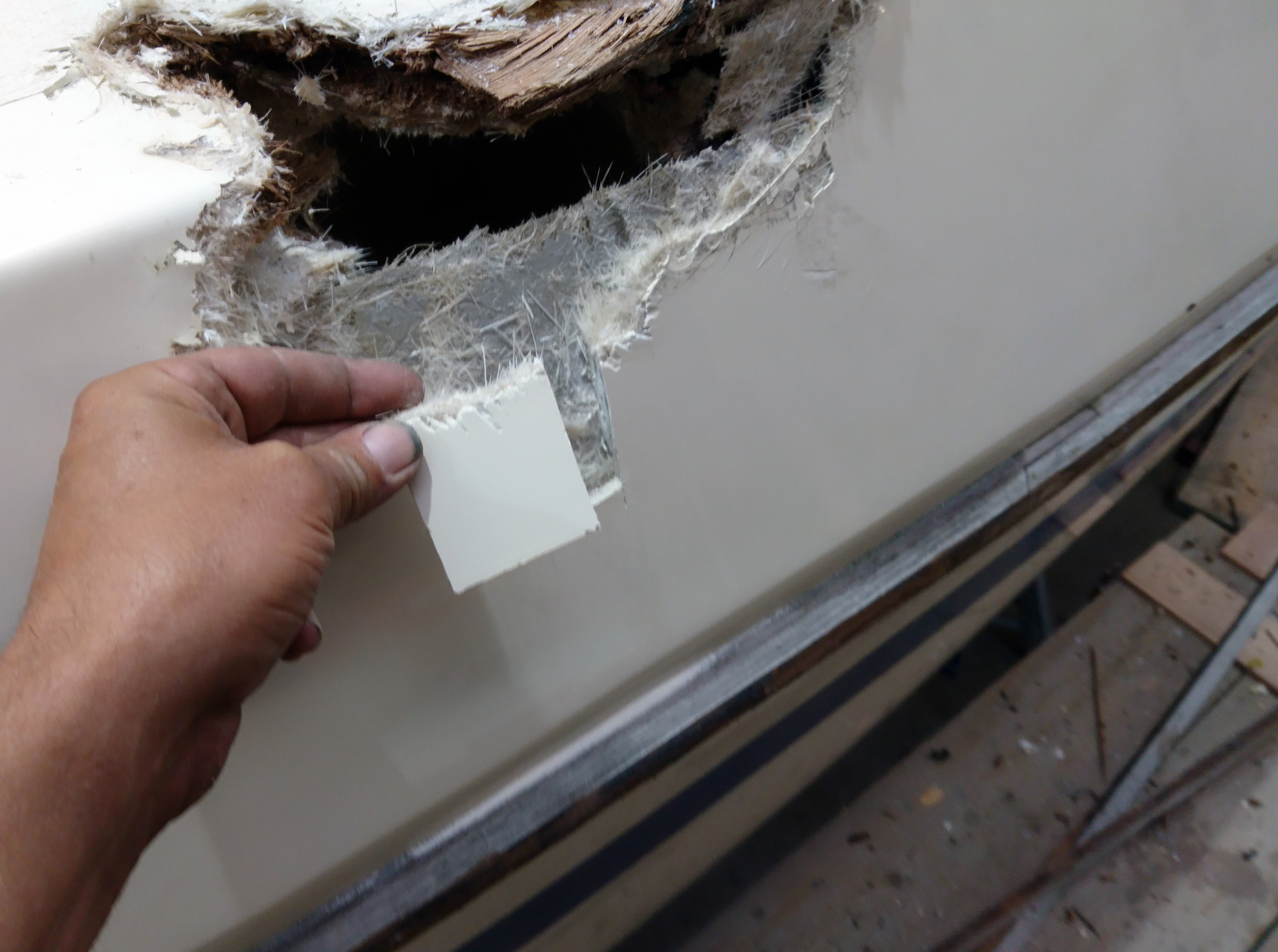
The crushed plywood core was cut away and all the jagged edges removed.
Its only at this stage, once all the bad stuff has been removed, that you can take a step back and come up with a rebuilding plan.
The choices really being repair from outside-in, inside-out or start in the middle.
I decided to firstly repair the deck core and then glass outside and then inside.
The plywood core was rebated by 30mm using a trusty multi tool, power file and various chisels.
A 12mm thick plywood infill section was made and dry fitted a number of times to get an exact fit.
The edges of the original deck core and the infill were sealed with neat West epoxy before being glued into position using a West epoxy/colloidal mix.
A 4mm vertical section of ply was also glued into place with epoxy to fill the gap and provide something to glass against.
It was very important to ensure that this was a clean bond and to ensure that there wouldn’t be any exposed epoxy either on the glass or plywood.
The reason for this is that polyester resin in not a good glue so for this job we use epoxy.
Trouble is Gelcoat is polyester based so the repair laminating will be using polyester resin.
The two are not great together so keep them separated.
Epoxy guru’s tell me that I can indeed use Polyester gel coat with epoxy but in this case I’m sticking with polyester.
Laminating with epoxy is a lot more time consuming with much longer curing times not to mention two or three times more expensive.
After the crushed wood and laminate has been removed a repair plan can be decided on.
A new plywood core infill is shaped to fit into the rebate.
The plywood deck core is rebated by 30mm back to good undamaged material.
The new core is glued into place using West epoxy and colloidal silica.
Any damaged glass laminate is ground away and the remaining glass is keyed and cleaned.
Inside another vertical section of ply is glued to the core to provide a good backing to lay up against.
The edge of the rebated plywood core is coated and sealed with West epoxy.
All the edges are tapered and keyed and all evidence of surplus epoxy is ground away.
The laminating process is pretty straight forward.
Wetting out the repair area first before laying on a layer of 450g chopped strand mat (csm).
I always tend to use csm for the initial layers as you get a stronger bond.
In this case I applied three layers of csm, ensuring each layer was well rolled and consolidated which in turn uses much less resin and will result in a stronger laminate.
Remember, resin rich layups are always more brittle and less strong, so be frugal with the amount of resin you use but at the same time ensure every fiber is whetted out.
A straight edge will show you where you have highs and lows in the laminate.
I mark these areas with marker pen and then its just a case of adding more localised layers.
Once there’s a good initial flat layup I can start adding a couple of layers of 350g woven biaxial cloth.
There was a lot more scope for additional layers on the inside repair, as this area will be hidden by internal trim.
So I added a number of extra layers of 450g woven tape which will add significant strength to the overall repair.
I use a masking tape border around the repair to avoid splashes and drips of resin landing outside the repair area.
I’ve seen others who need significantly more protection.
I take a lot of care about cleanliness during laminating, especially when using a consolidation roller and later in gel coating.
If you are not careful you can get into an almighty mess and then transfer that mess everywhere, so my top tip here is develop ocd type tendencies when laminating, although there are others who wish I could extend this tendency to other areas of my life.
First layers of CSM can be laminated.
Further layers of woven biaxial cloth are added.
Highs and lows are marked and filled using more glass to get a reasonably flat surface.
I added a few extra layers of 450g woven tape below decks.
After a quick trim and sand with 80 grit paper to remove the odd stray fiber it was time to apply the first coats of gelcoat.
The boat was inside our shed No3 and in early September the conditions were such that I could apply at least five or six coats of gel coat in a day.
Avoid the temptation to apply thick coats of gelcoat, which is very possible as gelcoat is much thicker than resin.
The issue is that during both the mixing process and the application you will introduce air bubbles into the mix which, if applied in a thick layer, will not work their way out to the surface.
Later sanding and compounding will expose these tiny bubbles which are impossible to fill.
The remedy to this is to apply multiple, thin layers of gelcoat.
I was getting gel cure times of around 1 hour, so I applied 5 thin coats during the day, followed by a coat with added wax in styrene which was then left to set hard overnight.
Next day the area was sanded with 240 grit paper using a flat foam block.
The initial hills and valleys are easy to spot as the valleys will remain gloss whilst the rest will be matt.
The trick here is to ring each valley with a marker pen and then remove the gloss using 80 grit to provide a good key.
Additional thin layers of gelcoat were then applied to fill the valleys before another coat over the whole area with added wax.
Its much harder to spot the highs and lows at these later stages so I scribble all over the area with a marker before sanding off using finer and finer grades of paper.
I find 240 grit is my rough starter paper.
This is followed by 600 grit, then 1000, 1500 and if I’m feeling enthusiastic I’ll scribble and sand off using 2000 grit wet and dry paper.
Numerous thin layers of gel coat are applied to build up the profile.
Numerous thin layers of gel coat are applied to build up the profile.
A coat with added wax is added so the surface can be sanded and checked for highs and lows.
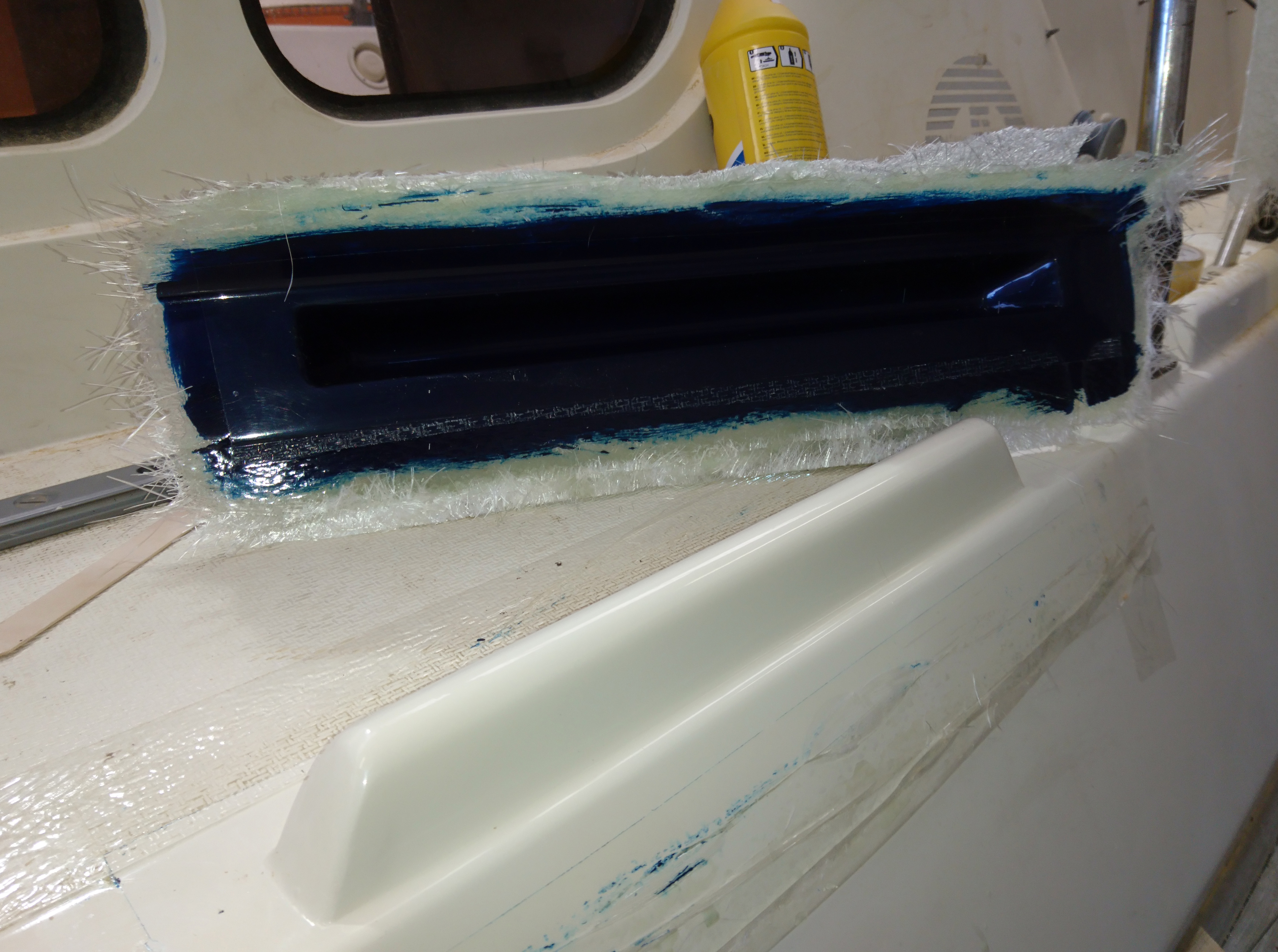
The next stage was to create a new toe rail.
For this I decided to take a mold from the opposite port side toe rail.
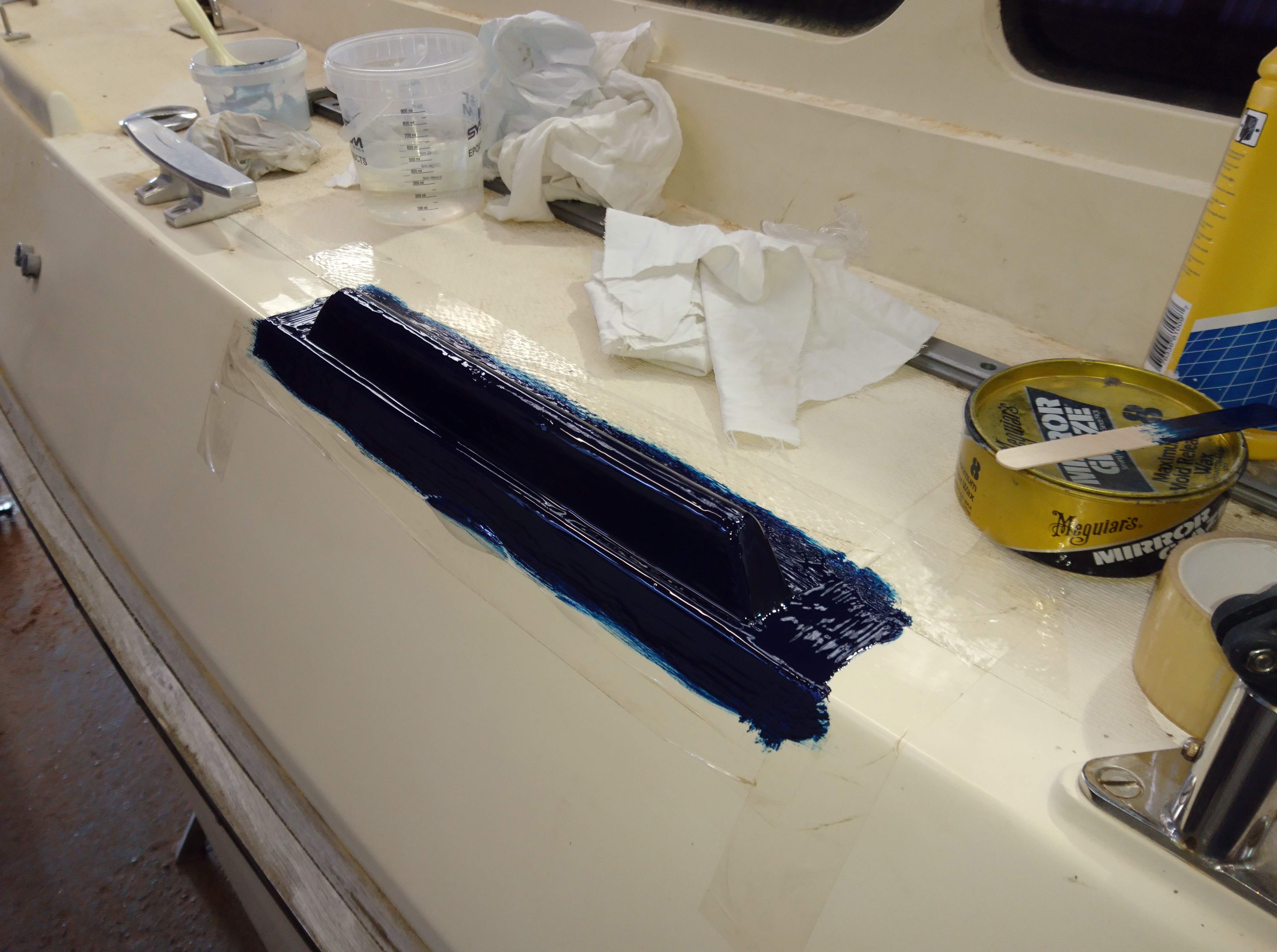
The port side toe rail was cleaned, compounded, polished and then had four coats of mirror wax applied and finally buffed to a high shine.
The area around the toe rail was taped using resin proof tape to ensure I could easily get wedges under the mould to release it later.
For the mould I used a contrasting dark blue gelcoat.
This is done so that when making the final part you ensure you get a good coverage of gelcoat as if it’s too thin you will be able to see the blue showing through.
Six layers of glass was laminated over the gel coat.
The next day the mould was popped off using wooden wedges, trimmed and internally waxed and polished.
A new toe rail was then laminated, trimmed and offered up.
Toe rail is cleaned, polished and waxed.
The mould can then be trimmed and internally waxed and polished.
Contrasting gelcoat applied.
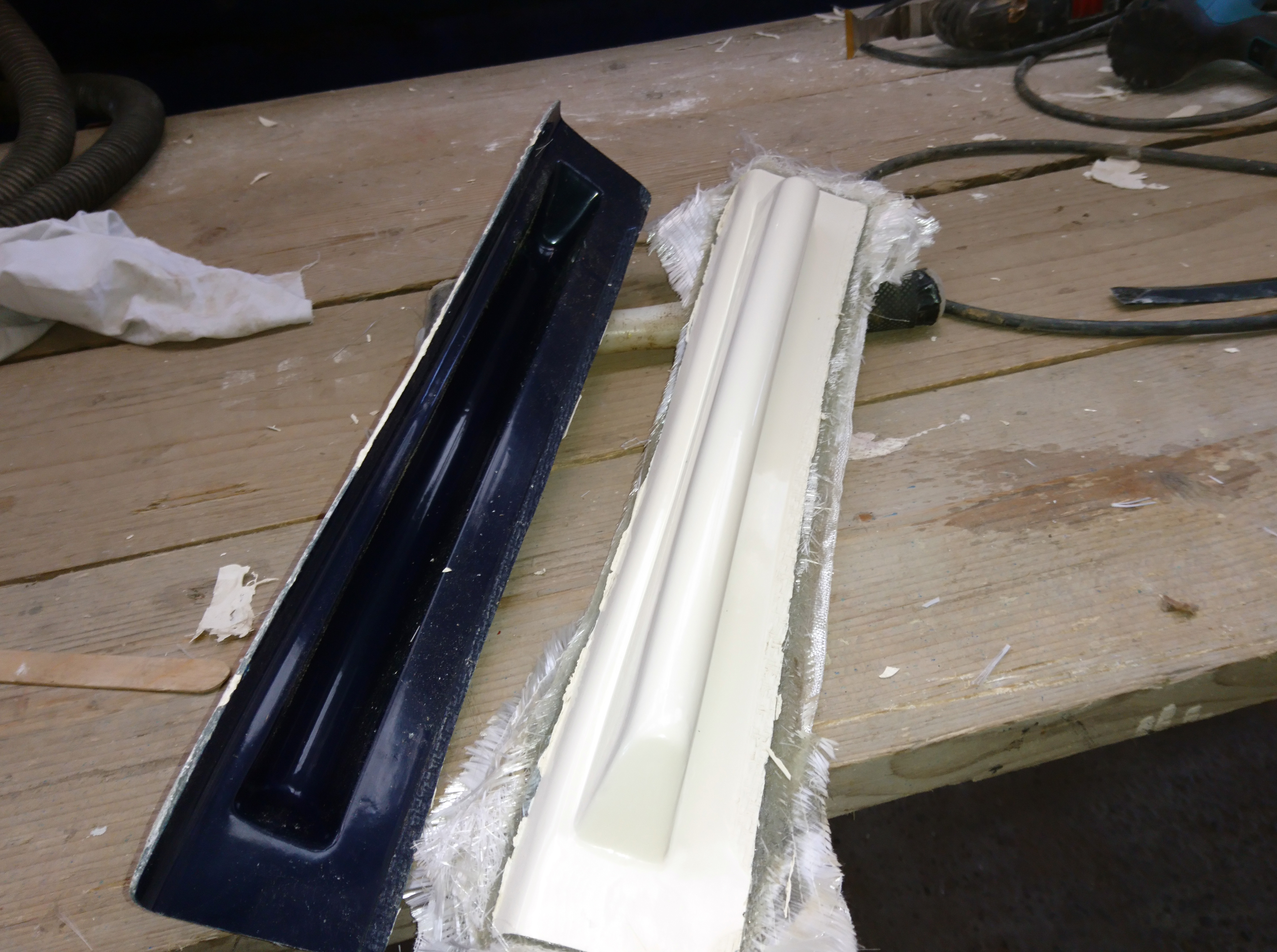
New toe rail popped out of the mould.
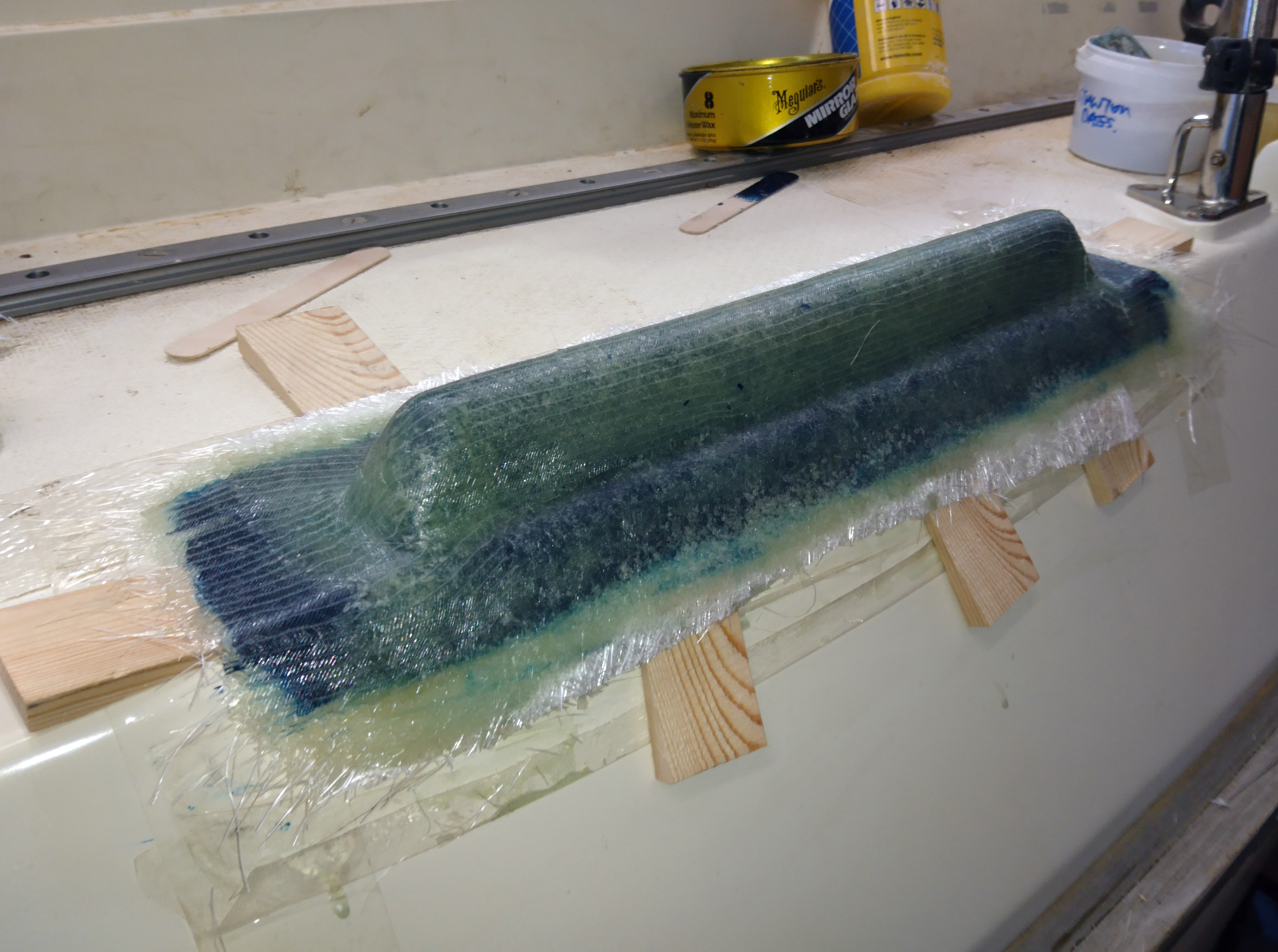
Half a dozen layers of 250g csm was used for the mould which was popped off using wooden wedges.
After trimming the toe rail is placed into position for marking up mounting points.
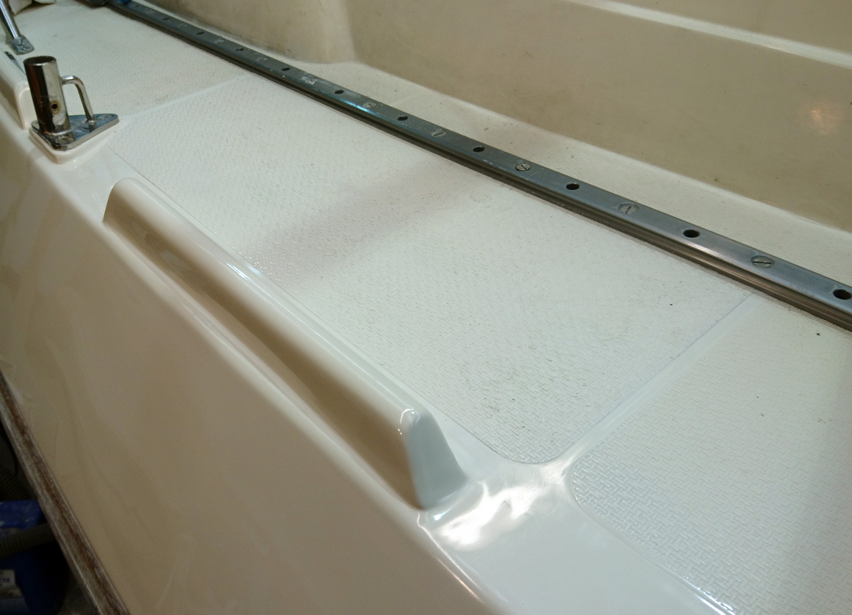
Possibly the most challenging part of this repair was to reinstate the molded in, non-slip texture on the deck.
A section of foredeck that had both the same pattern angle and roughly the same pitch was selected and the area was thoroughly cleaned, waxed and polished.
This was a lot harder to do than say as the wax tended to fill up the indentations so I used a stiff scrubbing brush over a soft cloth to ensure the wax was removed and polished.
I applied two coats of gelcoat followed by three layers of csm.
This resulted in a flexible mould that would flex to match the slightly different deck profile of the repair.
The mould was trimmed to the exact size and shape of the section of deck I wanted to recreate.
The corresponding area of deck was sanded hard to remove the old moulded grip and provide a good key.
As the non-slip stands up slightly from the surrounding gelcoat I needed to have a practice on a scrap piece of hardboard to judge how much gelcoat I would need as this repair would need to be done in one hit.
I found that a light coat on the deck and on the mould was just about right.
Starting from one end the mould was placed down onto the deck and by using the flex in the mould it was bent to avoid trapping any air as the two surfaces touched together.
A couple of push cramps and a lead weight were enough to hold the mould in position.
Once the gel had set, the mould was carefully peeled off revealing the non slip surface and a sigh of relief.
A mould was taken of the non slip pattern on the foredeck.
When released the deck pattern should be imprinted in the new layer of gelcoat.
This thin and flexible mould was released and trimmed to size.
When released the deck pattern should be imprinted in the new layer of gelcoat.
The mould was pressed down in position over a thin layer of gelcoat.
With the deck repair complete the toe rail needed to be secured to the deck.
I chose to make an internal wedge out of glass and this was bolted and glued to the deck using Sabatack.
In turn the wedge was coated with Saba and the toe rail pushed down over it.
It was just a case of adding a gelcoat fillet around the toe rail to merge it into the deck followed by the usual sanding, marking, sanding, polishing routine.
A final compound with 300 cut Farecla compound and then UV wax and it was time to grab one of the guys in the yard to see if they could spot the repair.
If you have to point out where the repair was made then you know you’ve been successful.
Internal toe rail lug glued and bolted to the deck ready to receive new toe rail.
Toe rail glued using Sabatack and clamped down over night.
A fillet of gelcoat was added around the join and once set can be sanded and polished.
Various shots of the finished repair…….
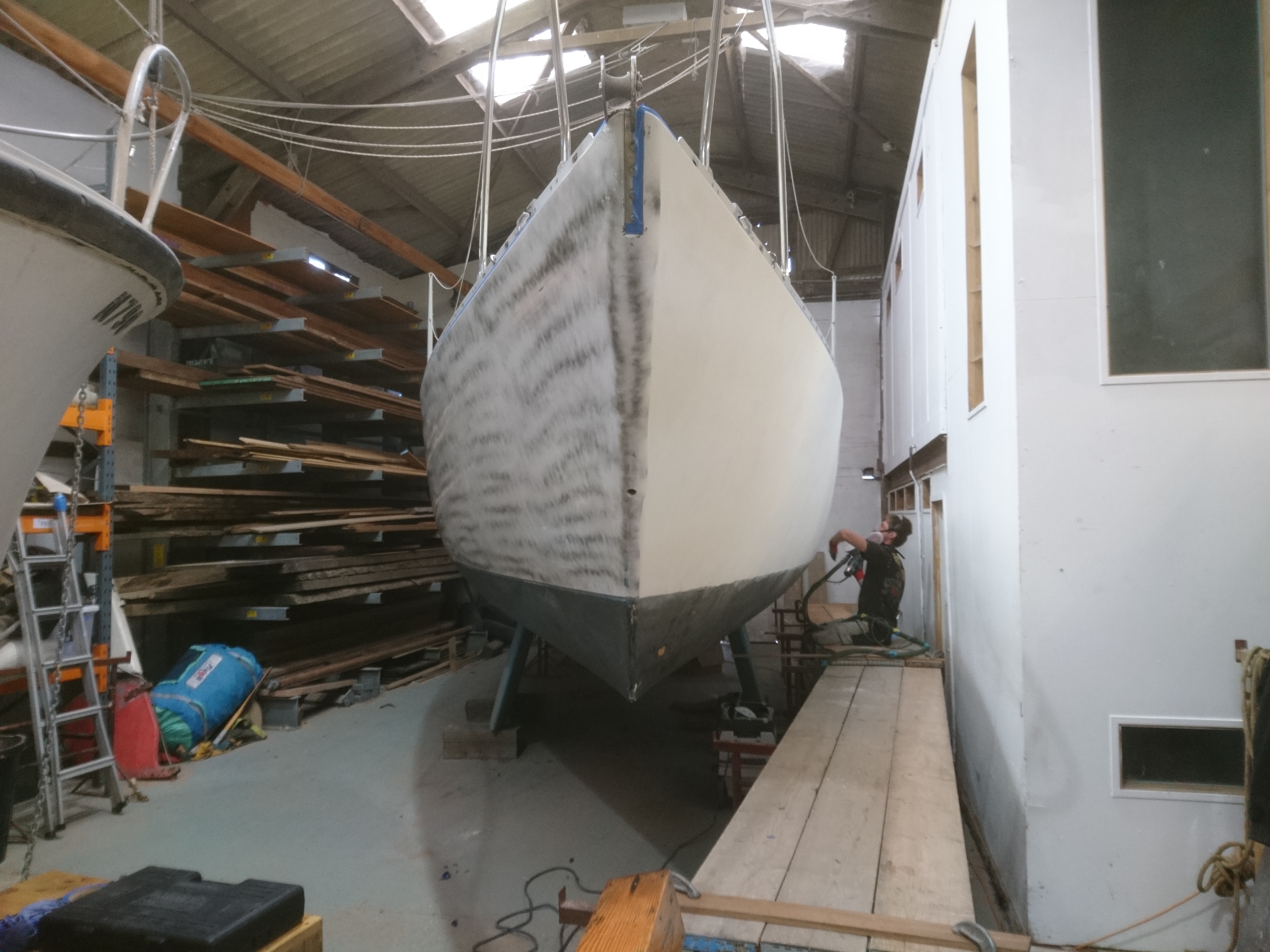
Grp boats are pretty resilient and after a bit of elbow grease is applied you can normally get a satisfying finish, even on a thirty or forty year old hull.
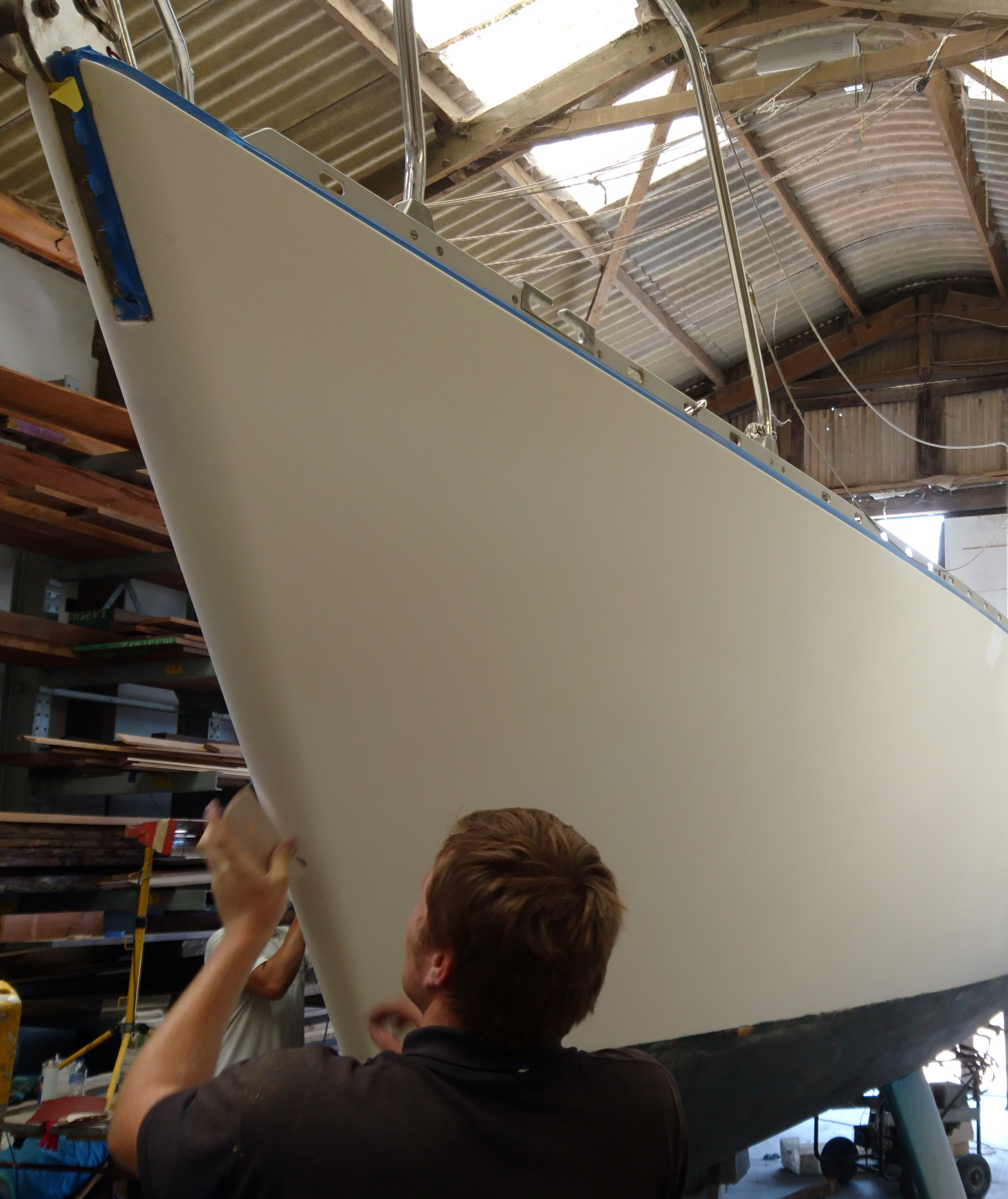
However there comes a time after years of compounding, polishing and scrubbing, not to mention dirty fenders, lifting slings, oh and the dreaded UV when there is just no way to get that shine back.
One option, if the damage is localised, is to re-gel coat.
However the general condition of this hull, though sound, was deemed to be too far gone to make this viable unless we re gel coated all the topsides.
Indeed if it wasn’t for the fact that we have a superb paint sprayer here I would have been tempted as the process takes only a little longer in man hours and gel coat is cheaper than good quality paint.
With spraying, the time is taken with the preparation, whereas with reapplying gel coat, the time is all in the final sanding and polishing.
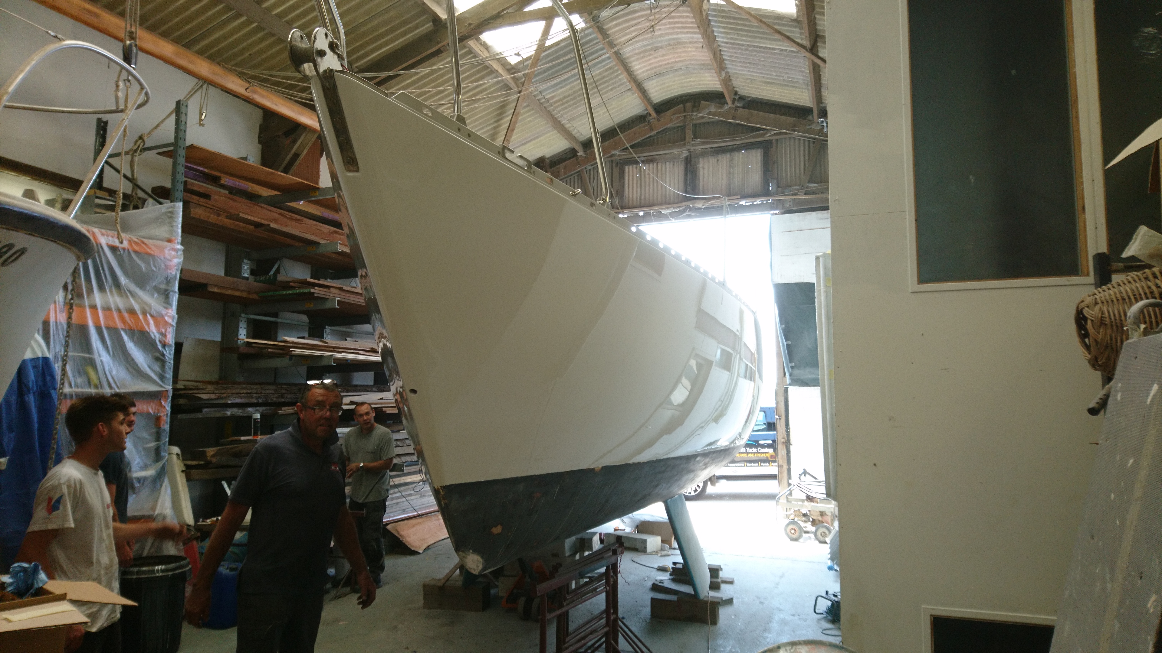
We spray a lot of boats here at the yard so for us this was the obvious route for this Moody 31.
The process is quite straight forward if a little time consuming.
The first job is to take lots of photographs from every conceivable angle.
These will provide a reference for the exact position of vinyl stripes, logos and names that all need to be removed and replaced.
The removal of these vinyl decals can often take much longer than you would expect.
The stripes in good condition will simply peel away given a little persuasion with a heat gun or even better a steam gun but where there are nicks or its worn thin other techniques using a mix of white spirit, Stanley blades and wet and dry sandpaper.
Every last trace of adhesive needs to be removed which is why we try to steer clear of aggressive solvents like acetone which dissolves the glue but with a high risk of spreading a thin layer of glue about when wiping clean.
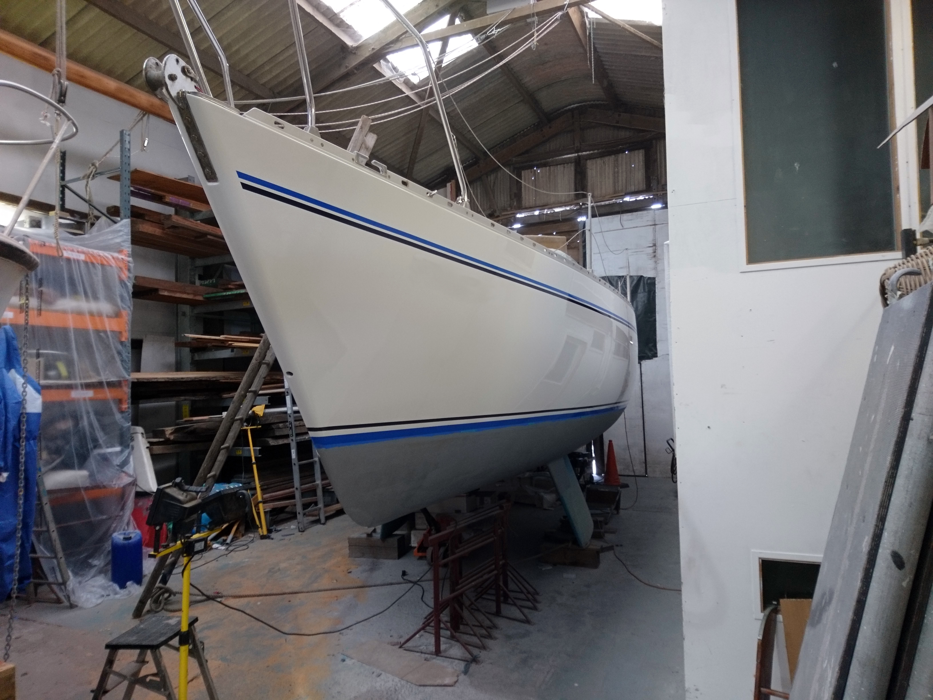
If you’re lucky the old vinyl stripes will simply peel off with care, if not a heat gun or steam will help.
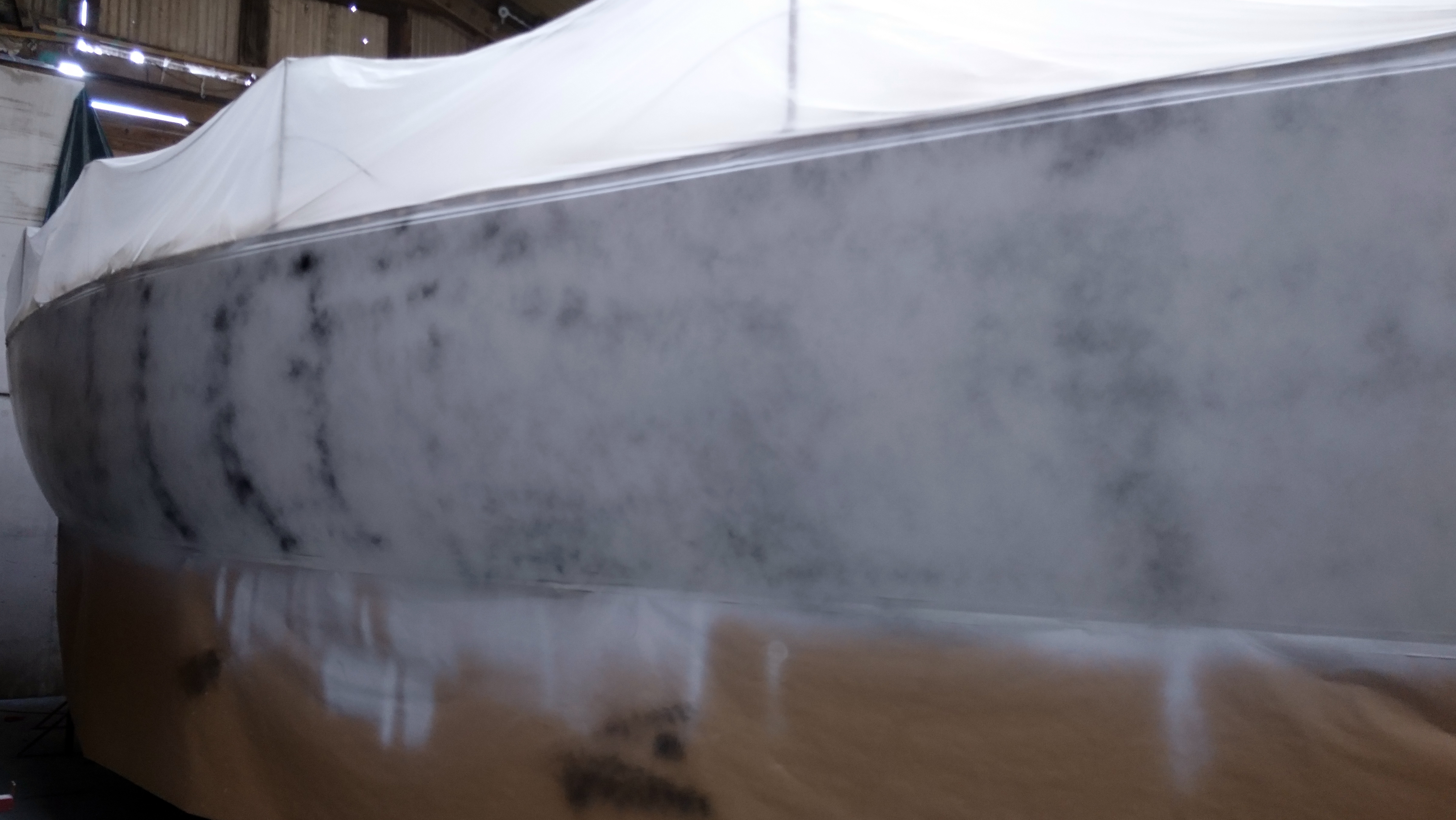
Obvious damage is one thing but its important to track and crazing with a pen so you can get it all ground away.
Any cracks missed will show through the paint in time.
Good lighting and even better eyes are now required to spot all the dings, chips and star crazing so that these can be treated next.
Often the best way is to sand down the entire topsides area using 150grit on a dual action (da) sander, though from this point on you need to employ very good dust extraction.
Dust is the make it or break it of a good spray job so we use dust extractors on each da and wash down at least twice a day.
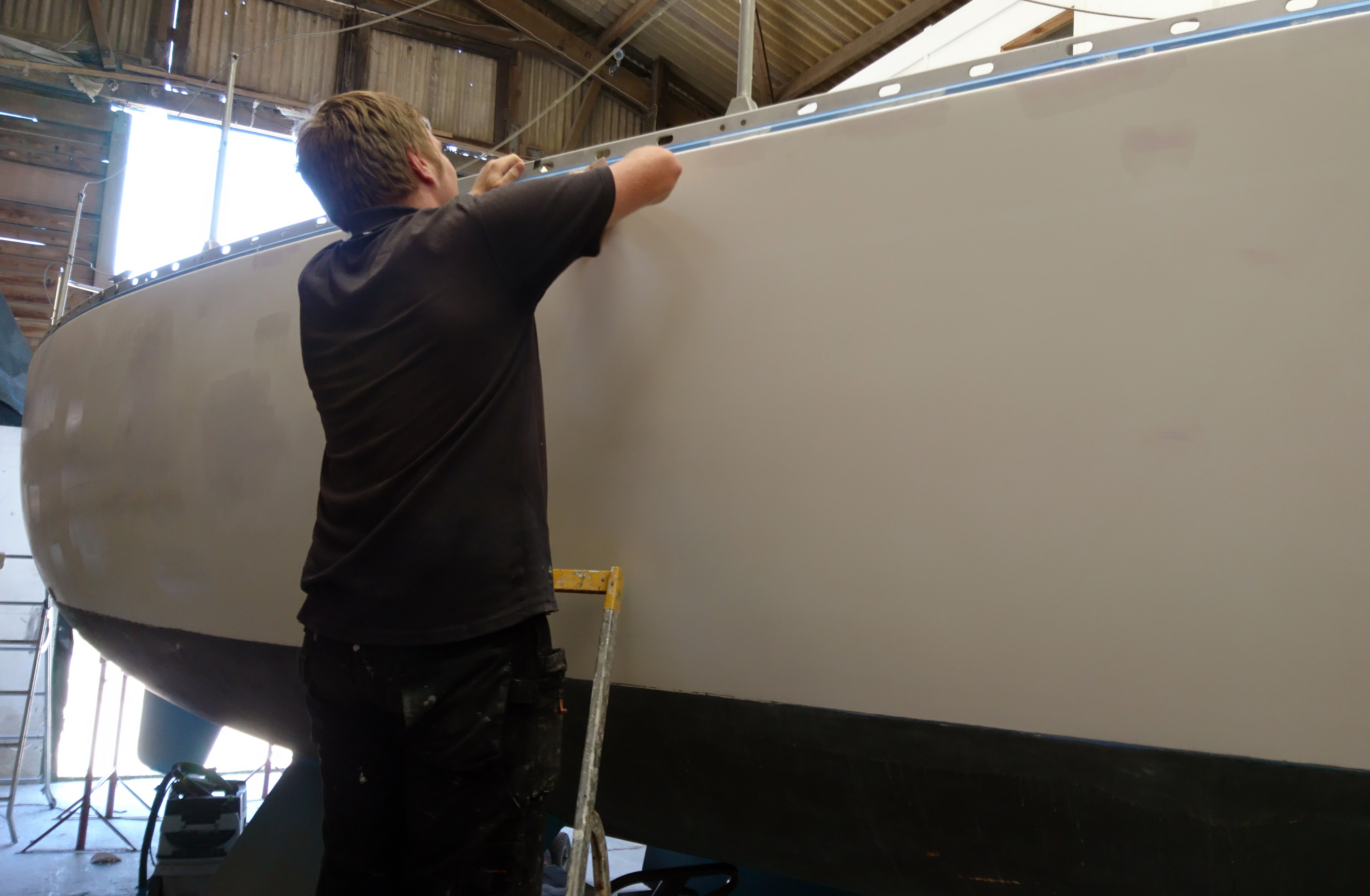
Also the deck and lower hull is taped up with a mix of plastic sheeting and brown paper.
During the course of the project the boat will be taped and re-taped a number of times.
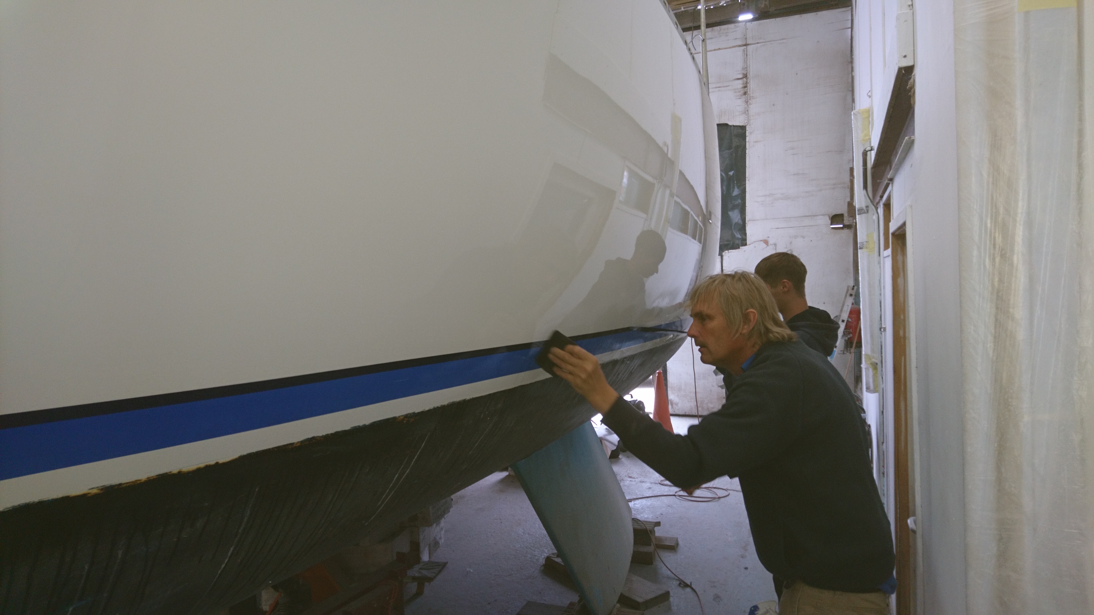
The damaged areas are sanded hard and the remaining gel coat is removed from the area.
This is especially true in crazed areas so we can also check the condition of the laminate.
We use the two pack Nautix epoxy fillers to fair and build up the damaged areas.
A long board is used to sand and fair in order to ensure we get a perfectly fair shape as once the top coat is applied any irregularities will stick out like a sore thumb.
White is a difficult colour to work with so we use a contrasting guide coat which helps us identify the highs and lows.
Dings, chips and grazes are ground away, filled and sanded.
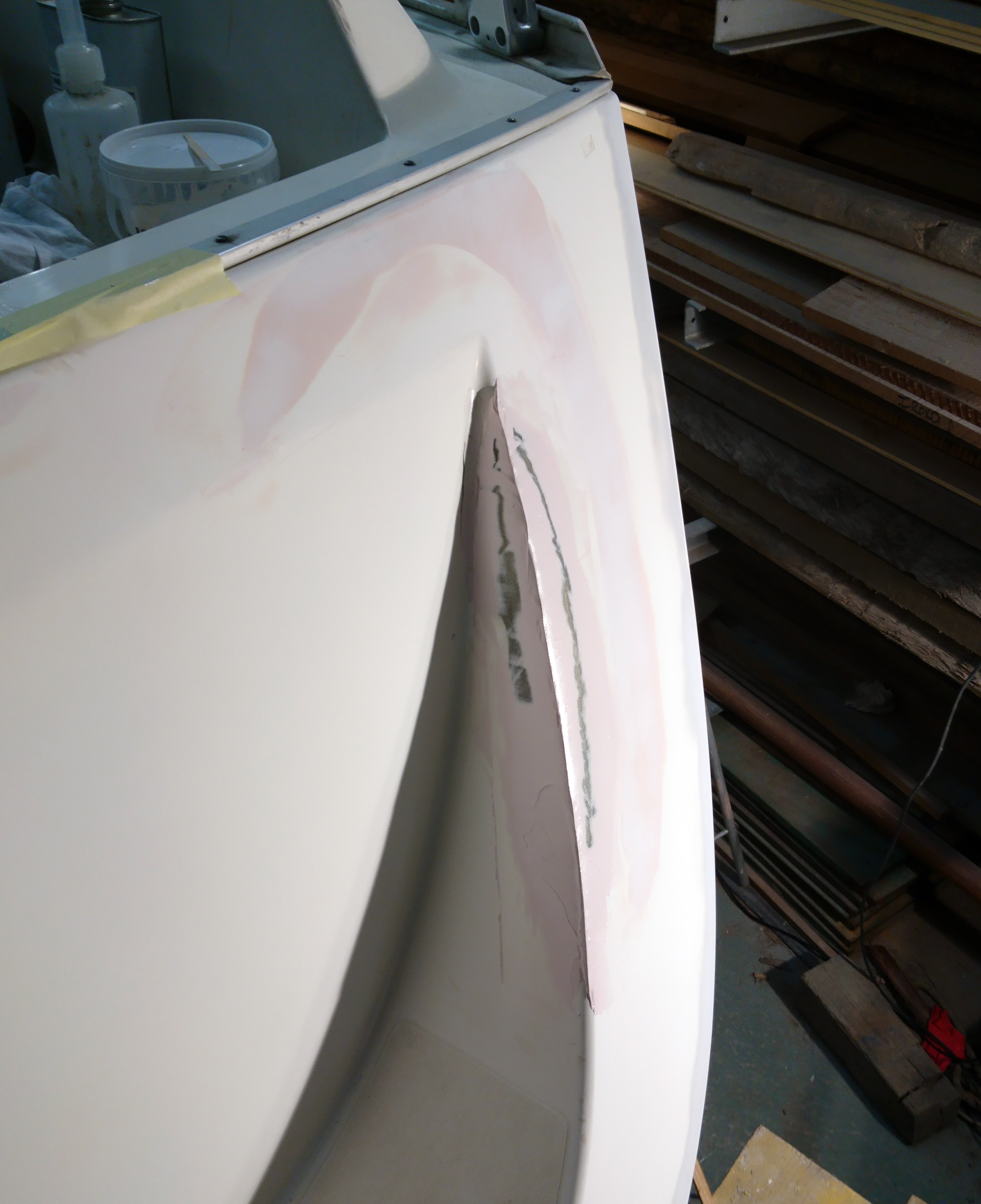
Crazing ground away and filled with epoxy whilst the laminate was repaired and strengthened from the inside.
We’ve had excellent and long lasting results using Awlgrip paints over the years and have got to know the system pretty well.
Once the major damaged areas have been dealt with the topsides are coated with the first of three coats of Awlgrip 545 epoxy primer.
This effectively seals the fairing and filled areas as well as providing a good base for top coats.
After the coat is dry we lightly spray a contrasting colour to act as a guide coat and sand back.
The guide coat will quickly show any high spots or valleys which can then be spot filled.
This process is repeated another couple of times until we are 100% happy that the topsides are true and fair.
Filler and fairing repairs can just be seen under the first coat of 545 epoxy primer.
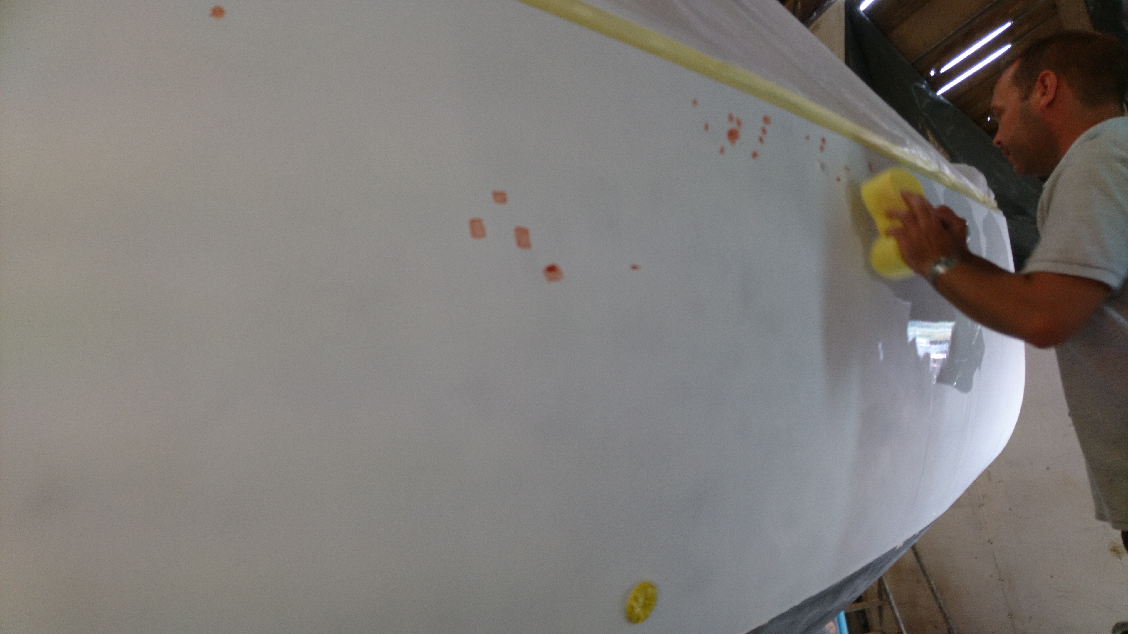
Attention to detail is vital at this stage as any inferfections will show up through the top coats.
The guide coat is applied slightly heavier in areas that have been filled so we can check for any filler shrinkage which can happen over a few days.
Glassed on the inside epoxy filled and fared on the outside having had third coat of 545 primer.
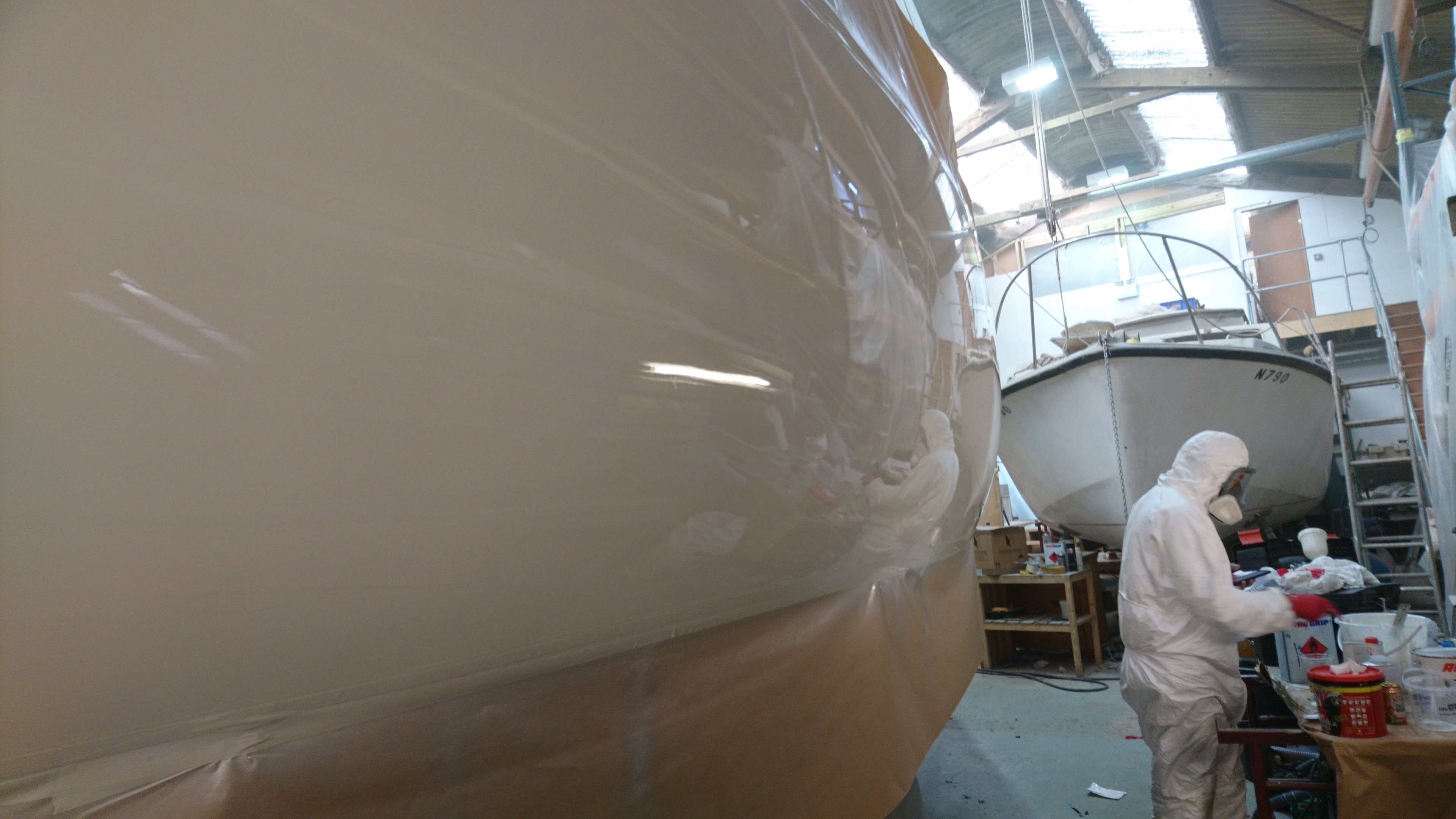
Everything is now washed, re-taped and a ban on entering the shed so we don’t get any errant airflow from opening doors disturbing unseen dust.
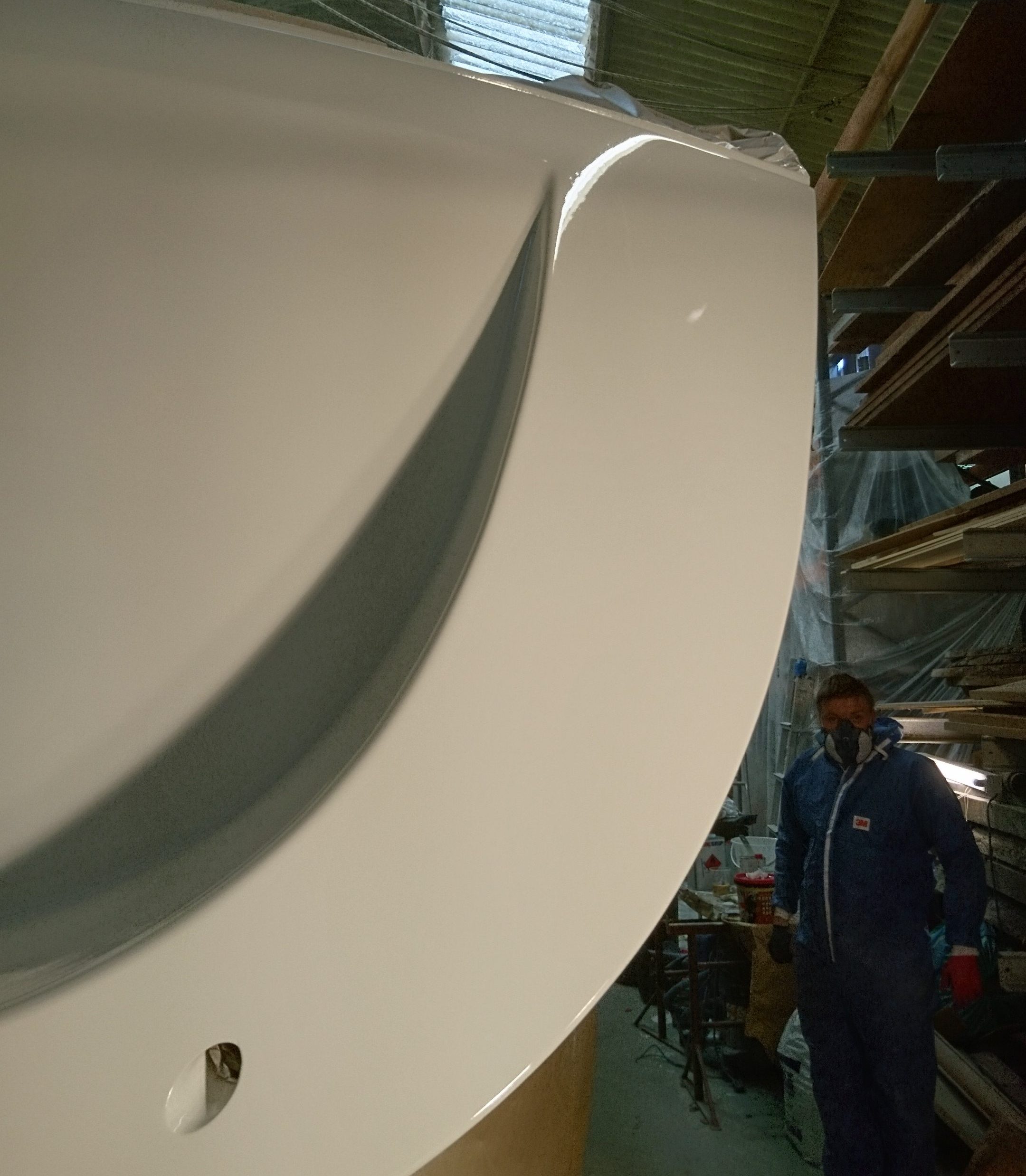
The first of three coats of Awlcraft 2000 topcoat can be applied.
This paint is a two part acrylic urethane high gloss which dries fast and seems to keep its shine for a long time.
Its also buffable so if/when you’re a bit late getting a fender in place you have half a chance to buff out the marks.
Three coats were applied over a 4 hour period. The best time for us to spray is on a Friday so it gets almost three days to semi cure.
Full cure takes a couple of weeks.
After the second of three top coats, things are looking good but its still a stressful time.
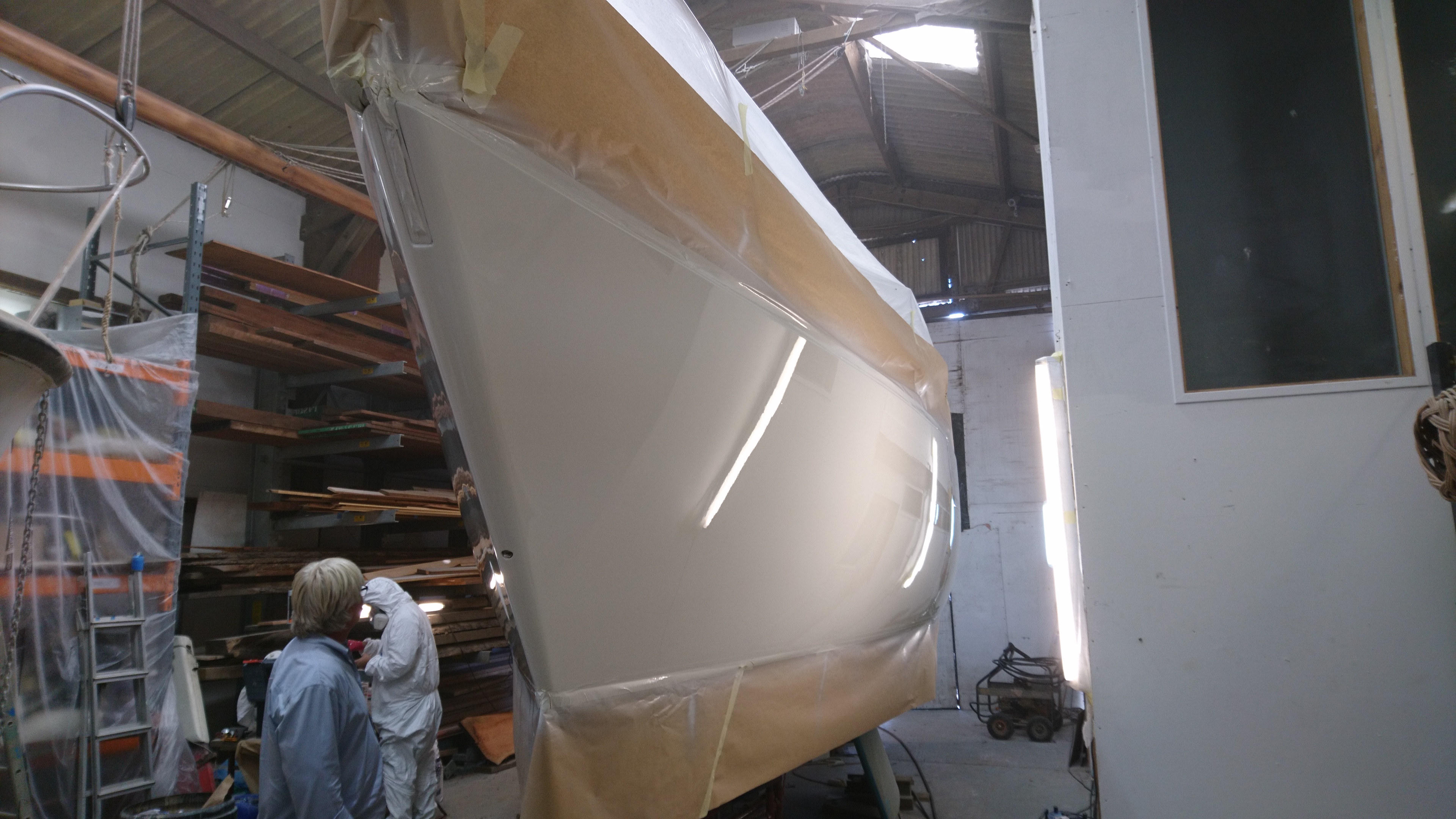
Third coat completed, the boss comes out to inspect.
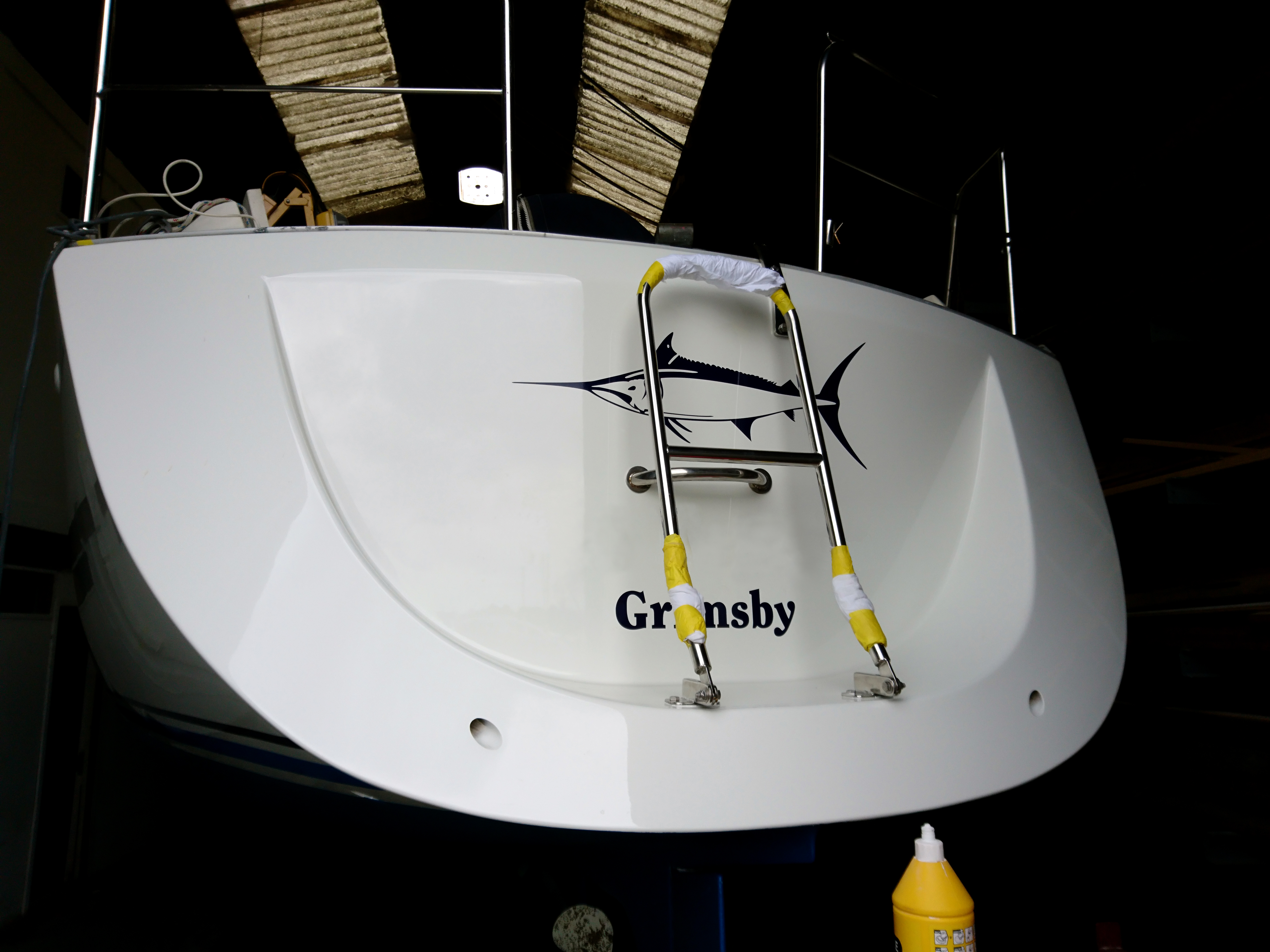
Its just a matter of applying the new vinyl stripes and decals and bolting back fittings like boarding ladders and getting her out of shed 3 in one piece.
A steady stream of our guys arrive to check out the new spray job.
New vinyls being applied.
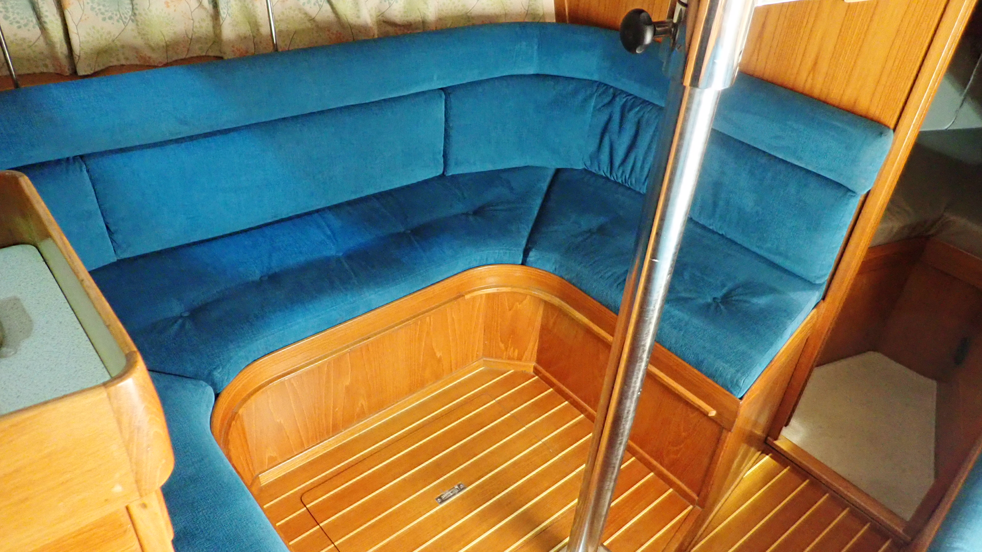
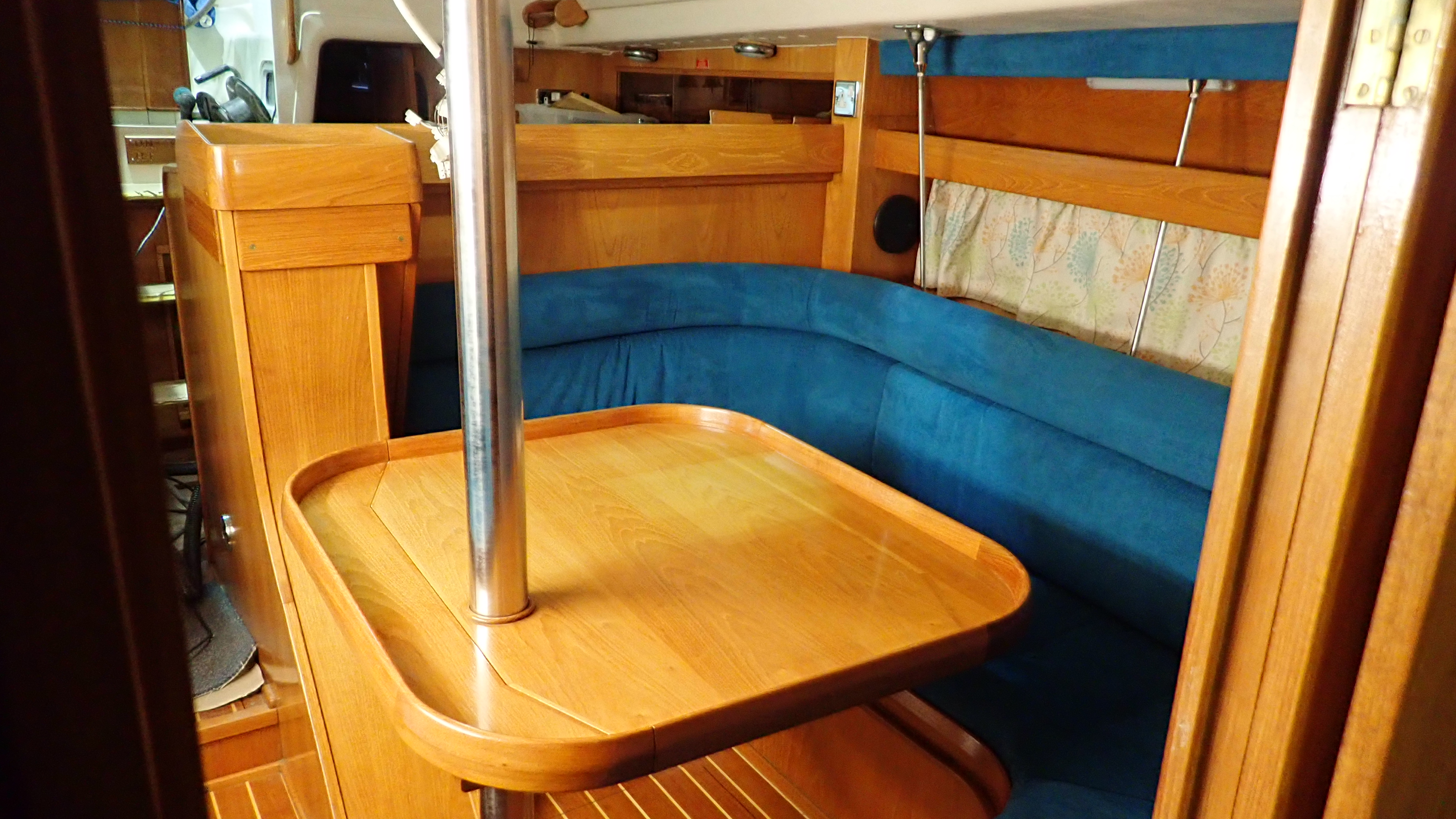
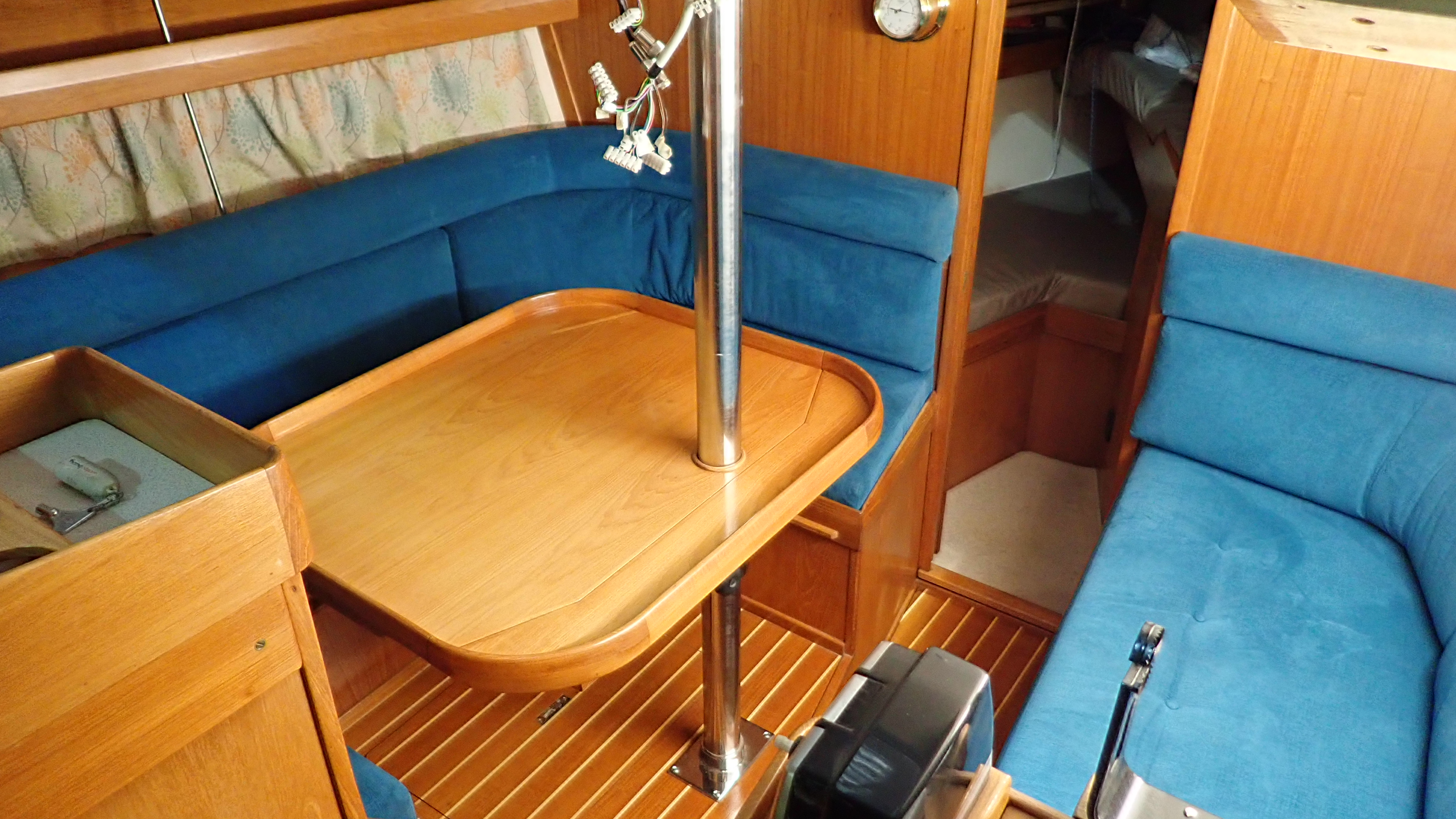
We’re currently working on a Nauticat 33 which having just been sold, is in to remedy issues found on the pre purchase survey and some new owner tlc.
The priority job was to install a compression post as the mast was in danger of becoming keel stepped instead of deck stepped.
I covered installation of a compression post on a Seamaster 925 in an earlier article and the solution was very similar.
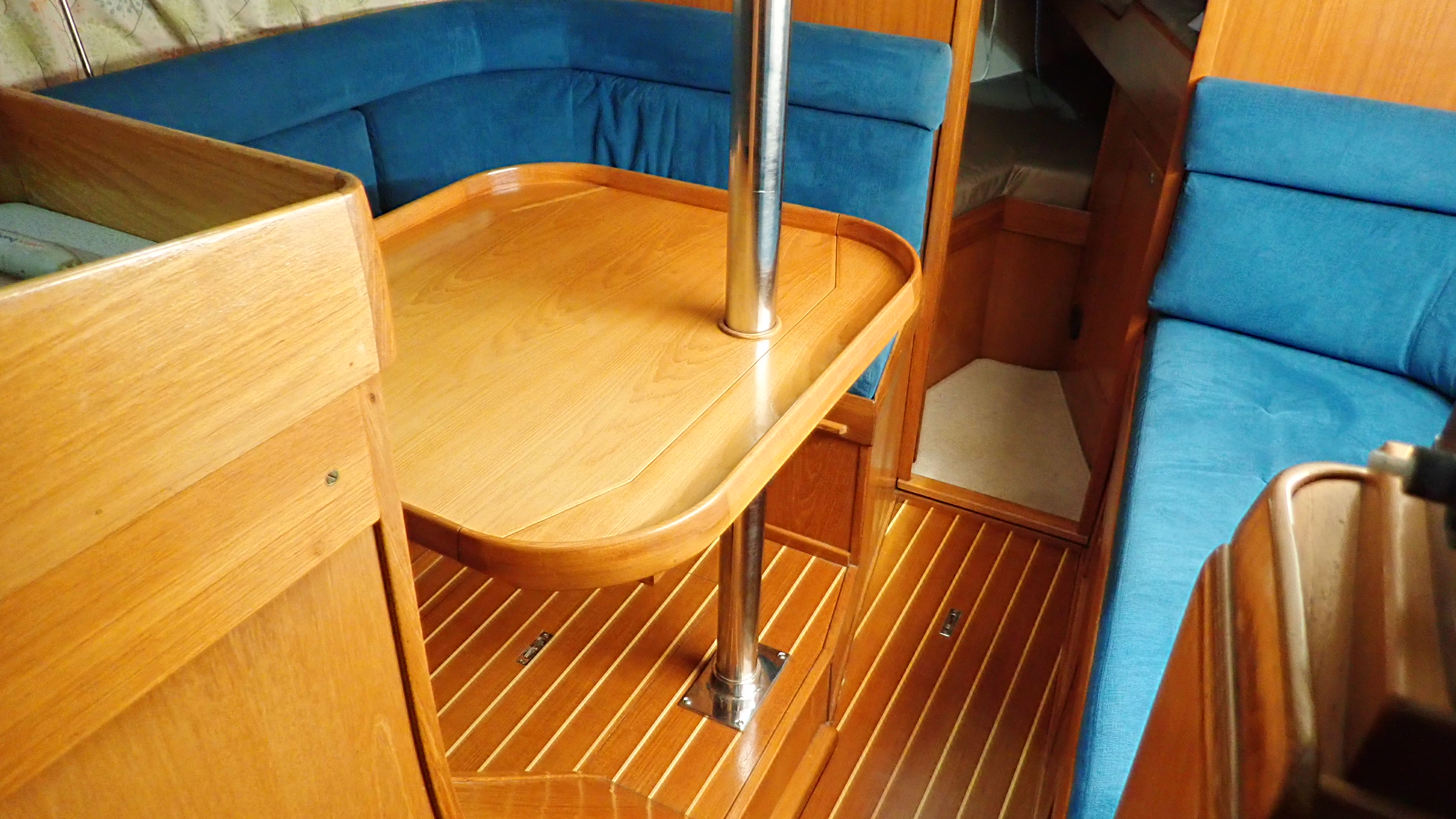
However we did have to change the soleboard layout on the Nauticat, especially in the heads which also doubled as a shower.
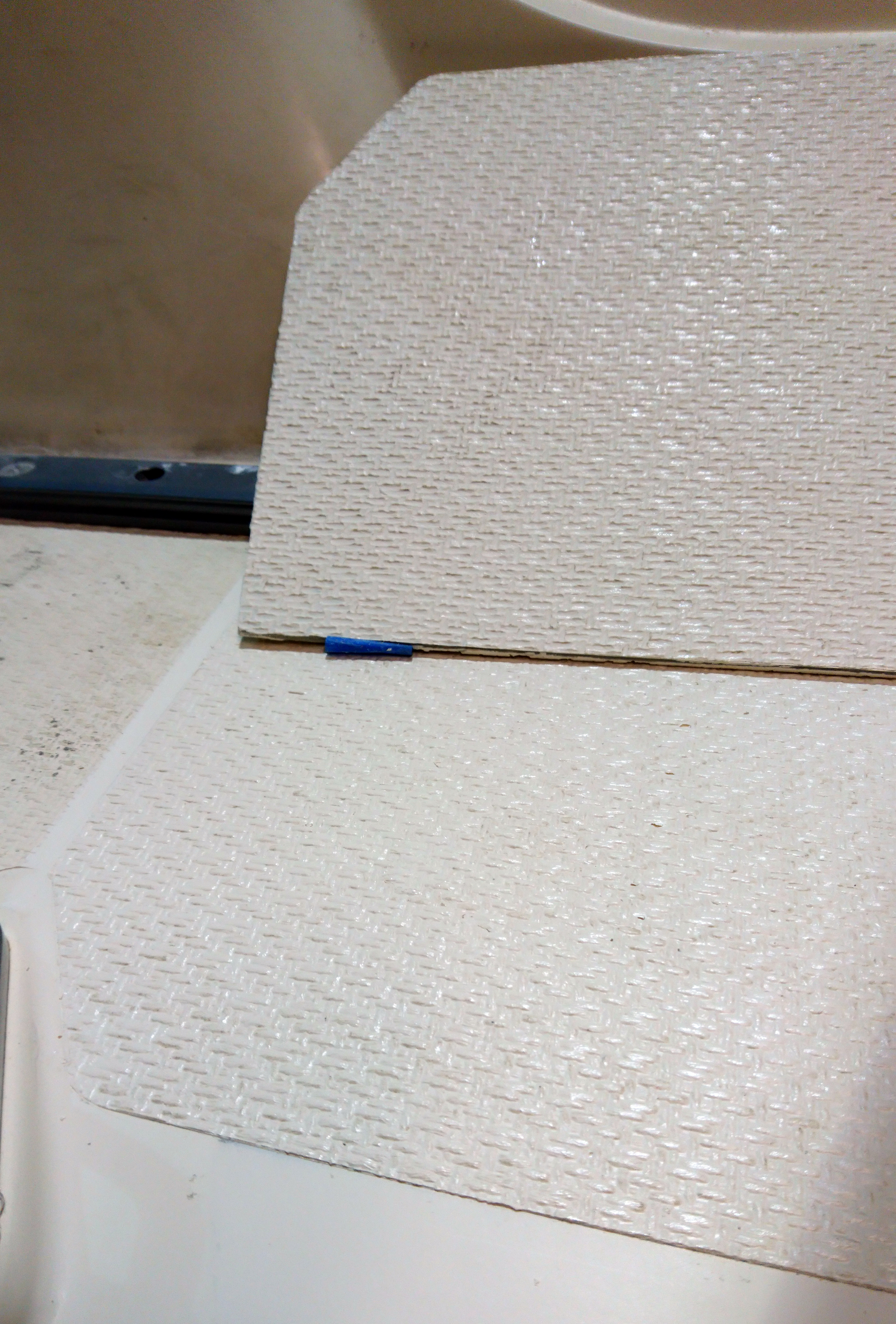
The original was plywood with a grp sheathe and gelcoat finish on top.
Unfortunately the underside was not treated and was merrily rotting away and as we had to cut a new shape board to accommodate the new stainless compression post we took the opportunity to make a new shower base.
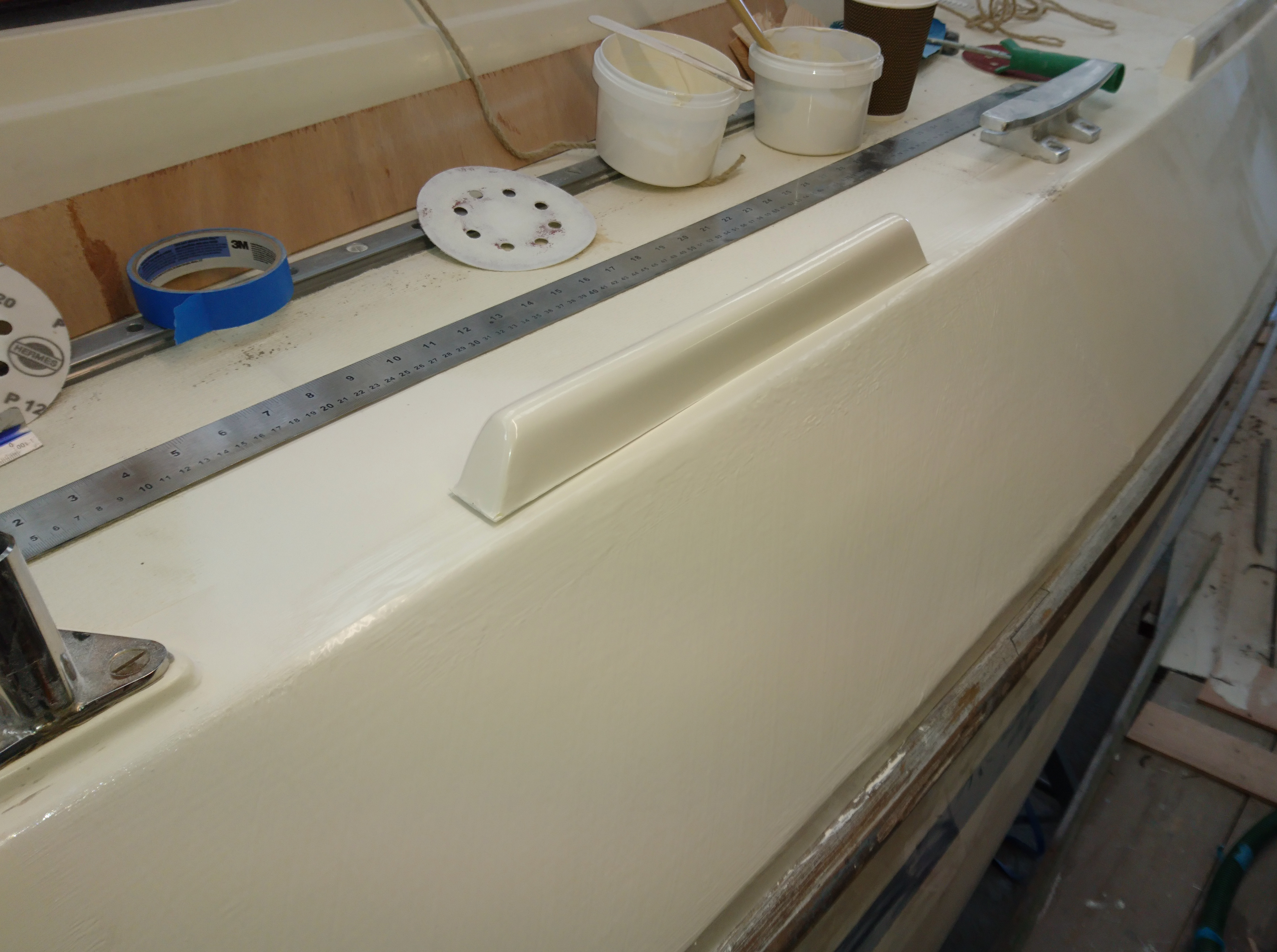
The base is to be made so it can be easily removed.
I personally do not like to make any areas of the hull inaccessible so whilst the current vogue is to have a permanent, nicely molded shower trays, this is not compatible with easy access to the inside of the hull.
The base itself is a strange shape so the first job was to create a template using 2″ strips of hardboard and a glue gun.
Using the template the 19mm marine ply can then be cut out and once a decision on the position of the drain plug has been made work can be carried out to make the flat surface somewhat less flat.
We used a small orbital sander and 40 grit pads and got creative.
Its hard to get grp to go round tight external turns such as edges and corners so as this base was to sheathed all the edges and corners have to be rounded off.
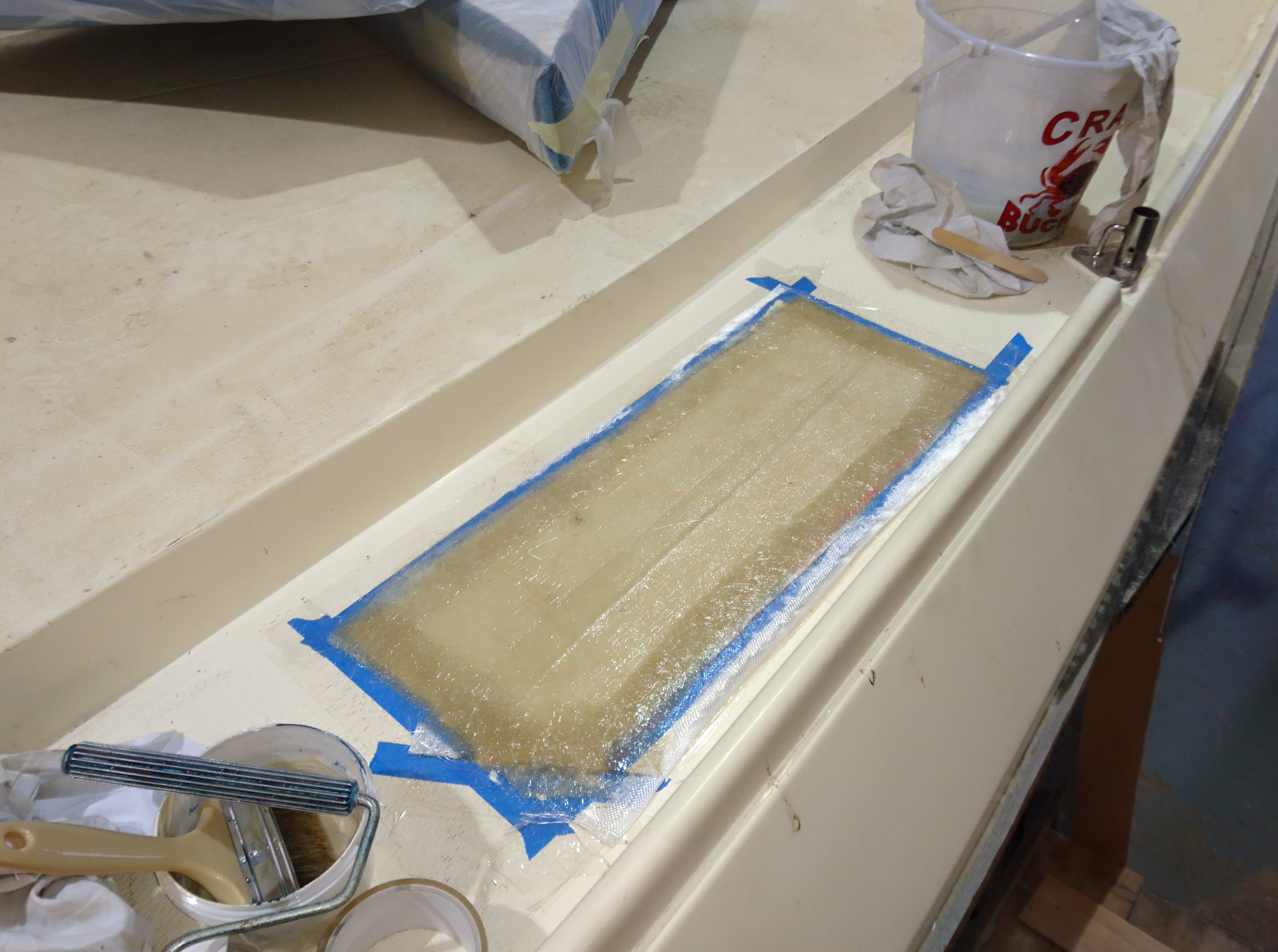
We were using polyester resin and to ensure getting a good bond between the ply and the glass I tend to use chopped strand mat (CSM) for the first layer as this in my experience has a far higher bond with a plywood surface than woven cloth.
We start the sheathing process on the bottom face of the base.
First coat the plywood with resin using a brush.
Paint it on, don’t ladle it on or pour it on and spread it about like you see on some you-tube videos.
All you need to do is wet out the surface before laying on a layer of precut 250gm csm.
Then using a brush add another light coat of resin before consolidating the layer with a roller.
If you have any dry areas add a little more resin but the trick is to use as little resin as possible.
Resin has very little strength in itself and using too much might speed up the wetting out process but the laminate will be resin rich and as a result will be weaker, brittle and less likely to bond well to the plywood.
Another reason for using just enough resin is cleanliness.
Some folk seem to get grp everywhere and end up with a huge mess and much of this comes down to the uncontrolled sloshing of resin which when you come to consolidation rolling will spray around in every direction.
Using polyester you have a great deal of control on cure times compared to using epoxy systems.
Adding a little more or less catalyst is a bit of an art and I find it hard to explain how much to use at specific times as I just seem to add just enough.
You have no such flexibility with epoxy systems such as West.
One sure fire way to speed things up though is to use a UV heat lamp which can allow me to get a workable cure in an hour or so.
Where epoxy wins though is in bonding strength to a substrate such as plywood.
However to mitigate this using polyester resin, creating a dust free, well scored surface helps immensely.
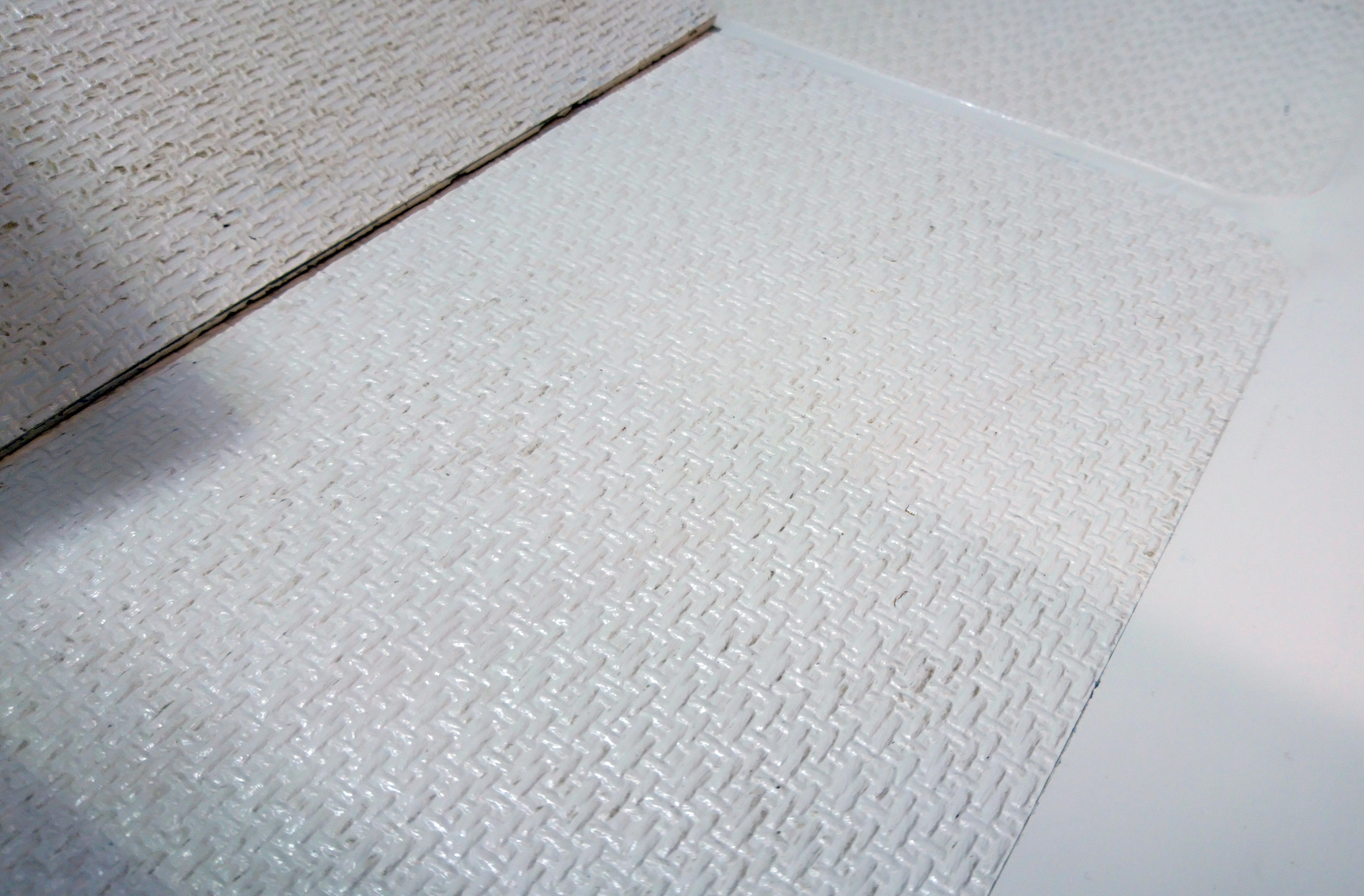
When sheathing the top surface we followed up the layer of csm with a layer of 300gm bi-axial woven cloth.
Again a light coating of resin and a good roll will pull up any surplus resin from the lower layer.
Using a slightly more resin on the edges to help the cloth round the corners and stay stuck down during the cure.
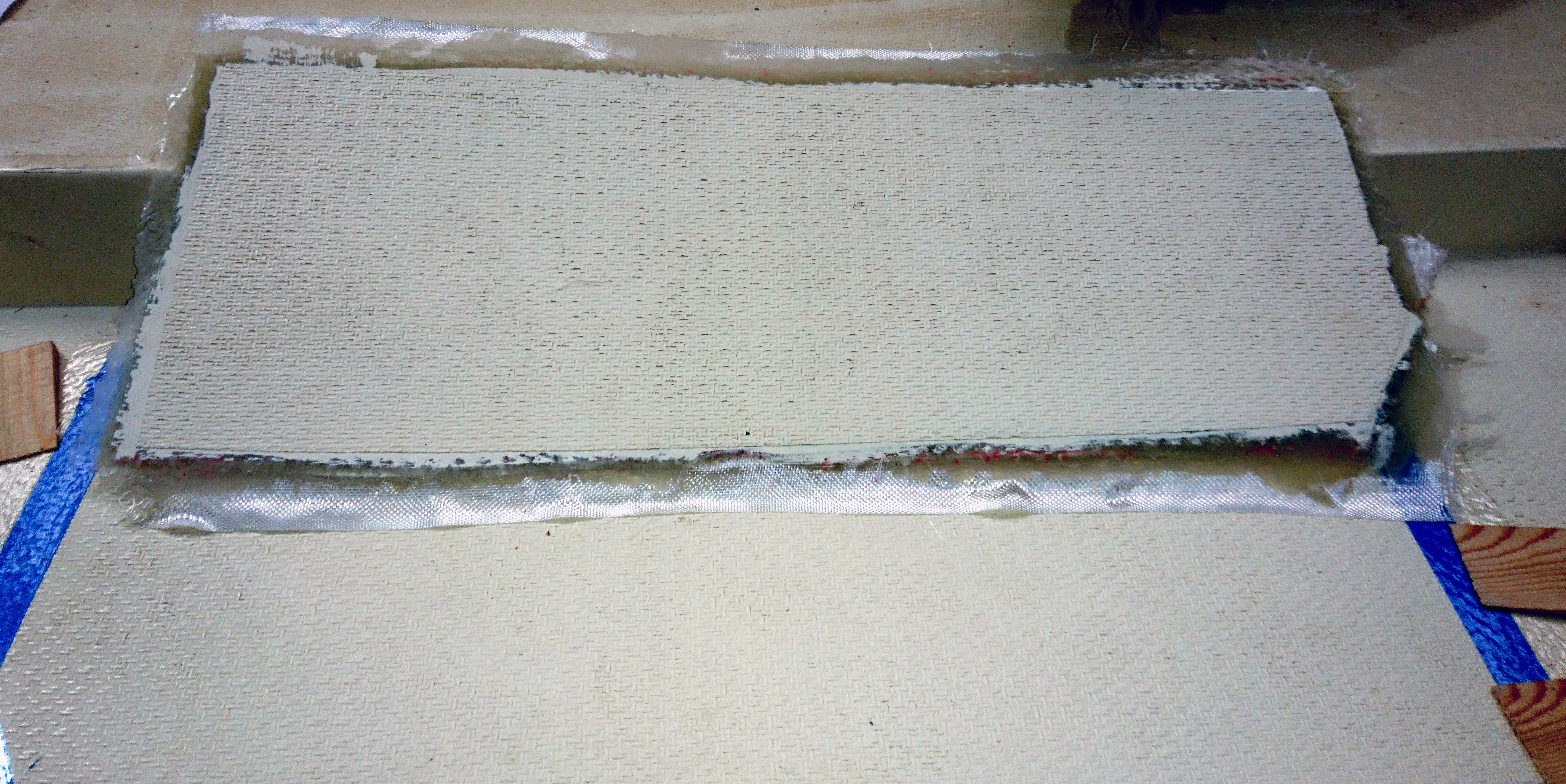
After trimming and a quick sand using 100grit paper round the edges its time to add 100mm wide glass tape round the edges.
Applying just the right amount of tension you can usually get the tape to lay nice and flat without too many creases.
The tape is thin, flexible and needs very little resin to wet out.
In this case I was adding the edge tape on a Friday afternoon so I added a little white pigment so that on my return the following week I would remember exactly where I’d got too.
The whole base was then rough sanded with 100 grit washed and dried.
Essentially the sheathing was complete and now was time to add the gel-coat.
Surface coating using gel-coat has one big issue and that is air bubbles.
You add air during the stirring process and then again during application with a brush, roller or spray.
Gelcoat is thick and its very tempting and perfectly possible to add two or three mm of gelcoat at one time and after an initial cure will look pretty good.
Until that is, you start to sand and then cut/polish the surface and then you will see lots of tiny holes in the surface.
Sanding or cutting further might remove these initial holes only for others to emerge underneath.
The way round this is to apply multiple thin layers.
I like to use four layers and then a top layer with added wax in styrene. (also known as topcoat or flowcoat)
The wax comes to the surface and seals off the gelcoat from the surround air and allows it to cure, otherwise it will always remain tacky.
Once cured the area can be sanded flat using 100grit paper which removes any major bumps and hollows and provides a key for the finish layers of gel.
The radius edges needed to be squared off so a wood frame was put together.
A resin proof tape that looks similar to sellotape was applied to the surfaces of the wood so that it would not stick to the gel coat.
Further layers of gel was then applied and the edges filled.
Once cured the frame is simply removed leaving a square edge.
The final process is marking, sanding, marking and more sanding until you’re happy with the surface fairness, followed by cutting with a suitable cutting compound.
Most fast cut cutting compounds will remove scratches made by 1000 grit wet and dry paper and you will get a pretty good surface finish.
I like to go a couple of stages further with 1500 and 2000 grit paper before cutting with a fine cut compound as the finish is in my eyes superior and seems to stay cleaner much longer.
The decision on level of finish usually comes down to customer preference as the 1500/2000/cut/polish would be another hours work.
Though to be honest I quite often do it anyway for my own piece of mind and keep it under my hat, oops.
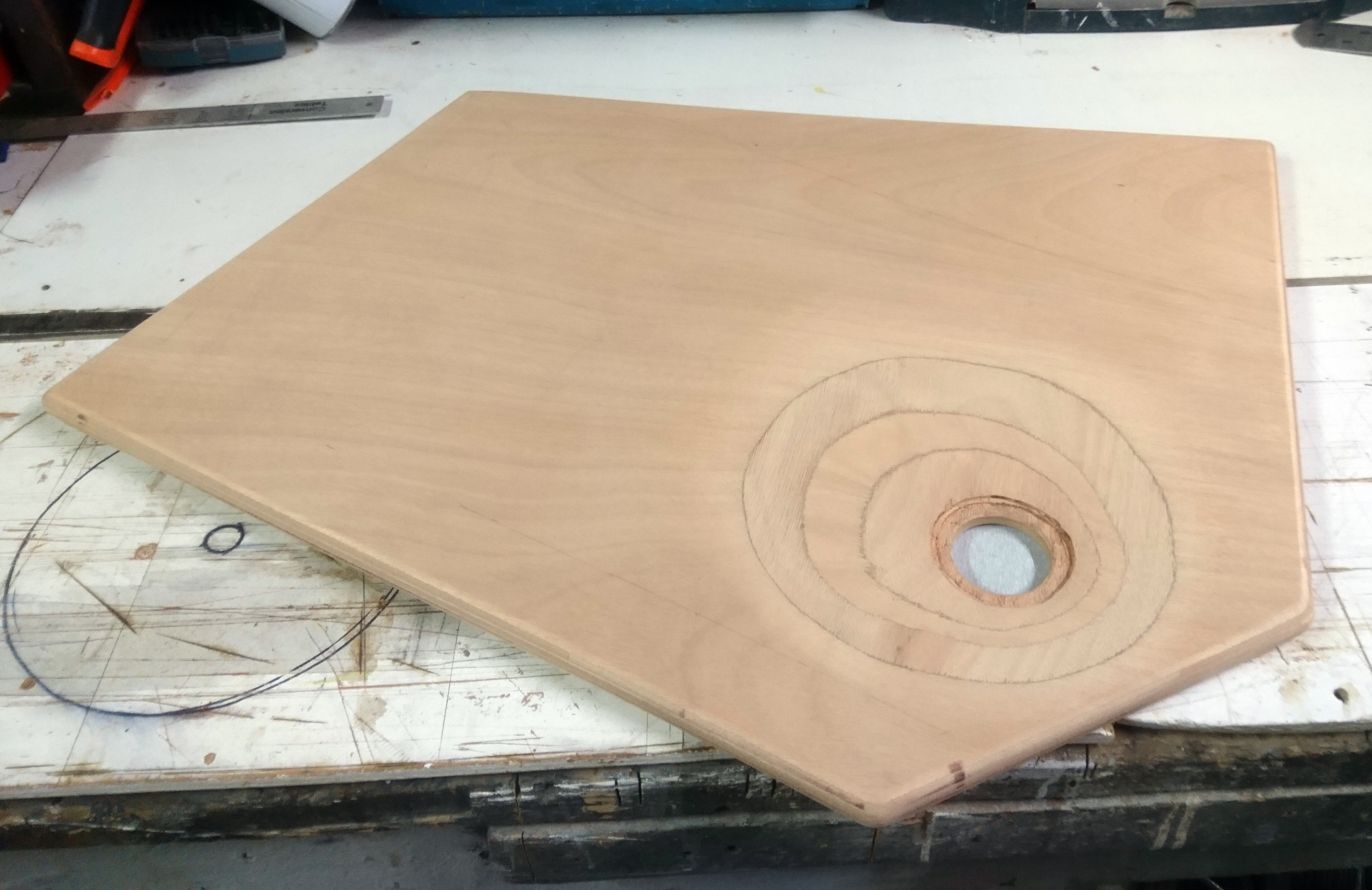
Use a sander to shape the flat board so the base will drain.
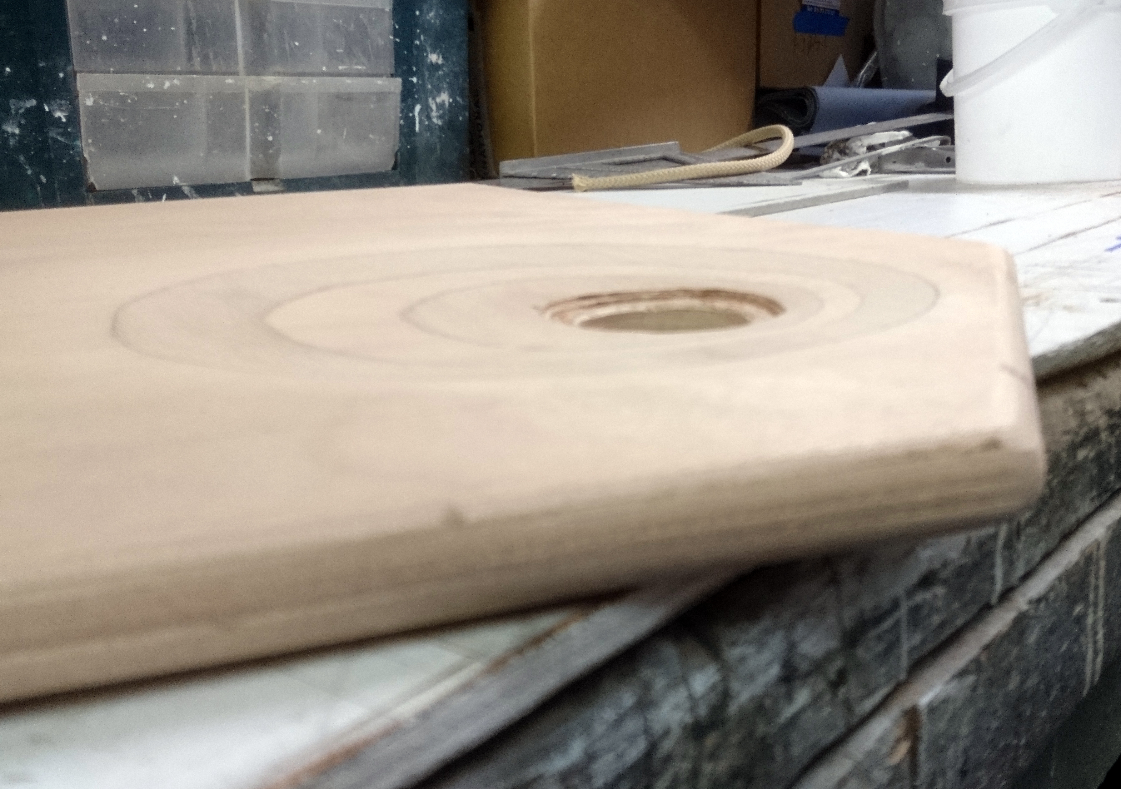
Radius the edges and corners to aid sheathing.
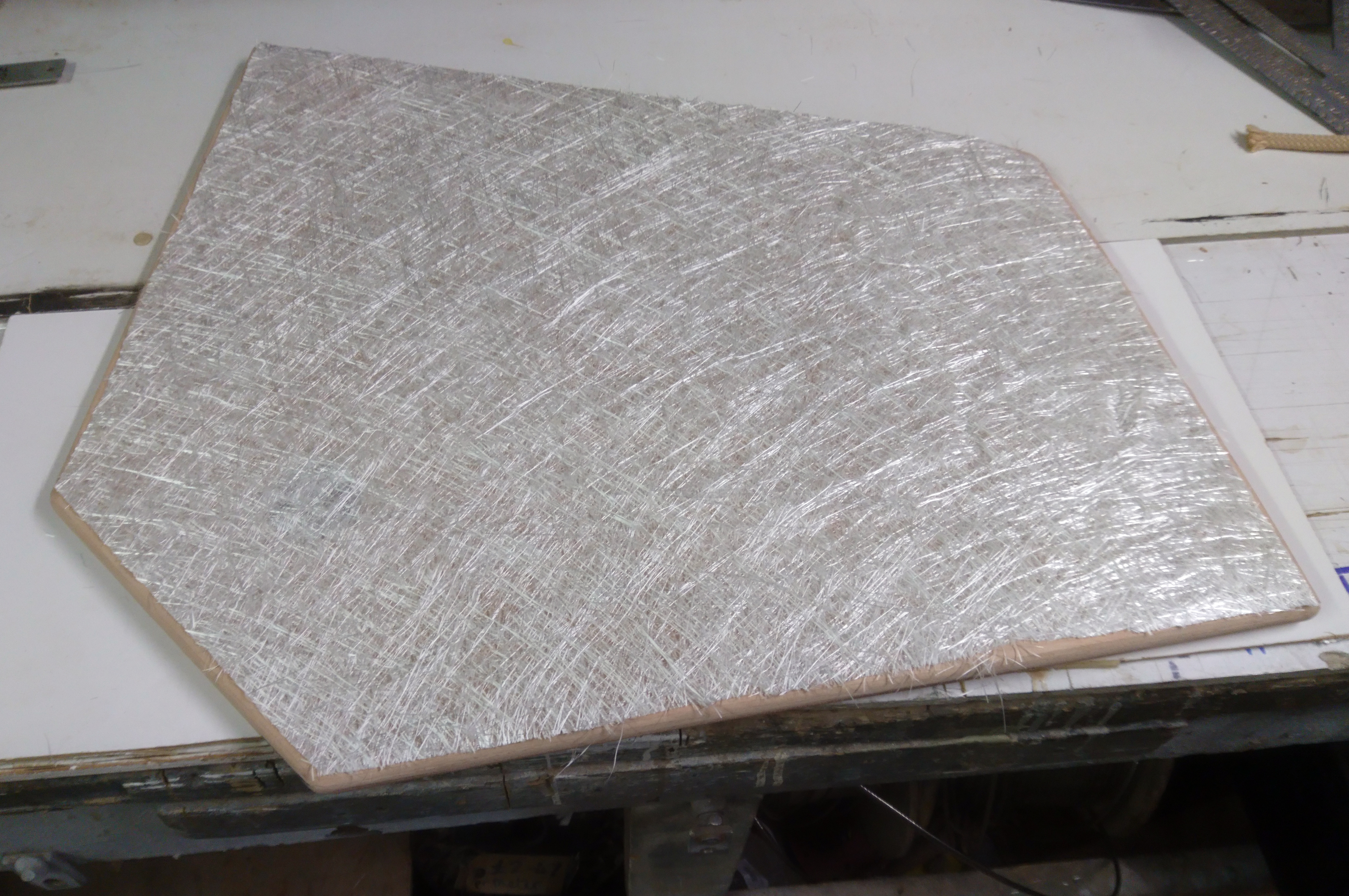
Cut out the glass before you start.
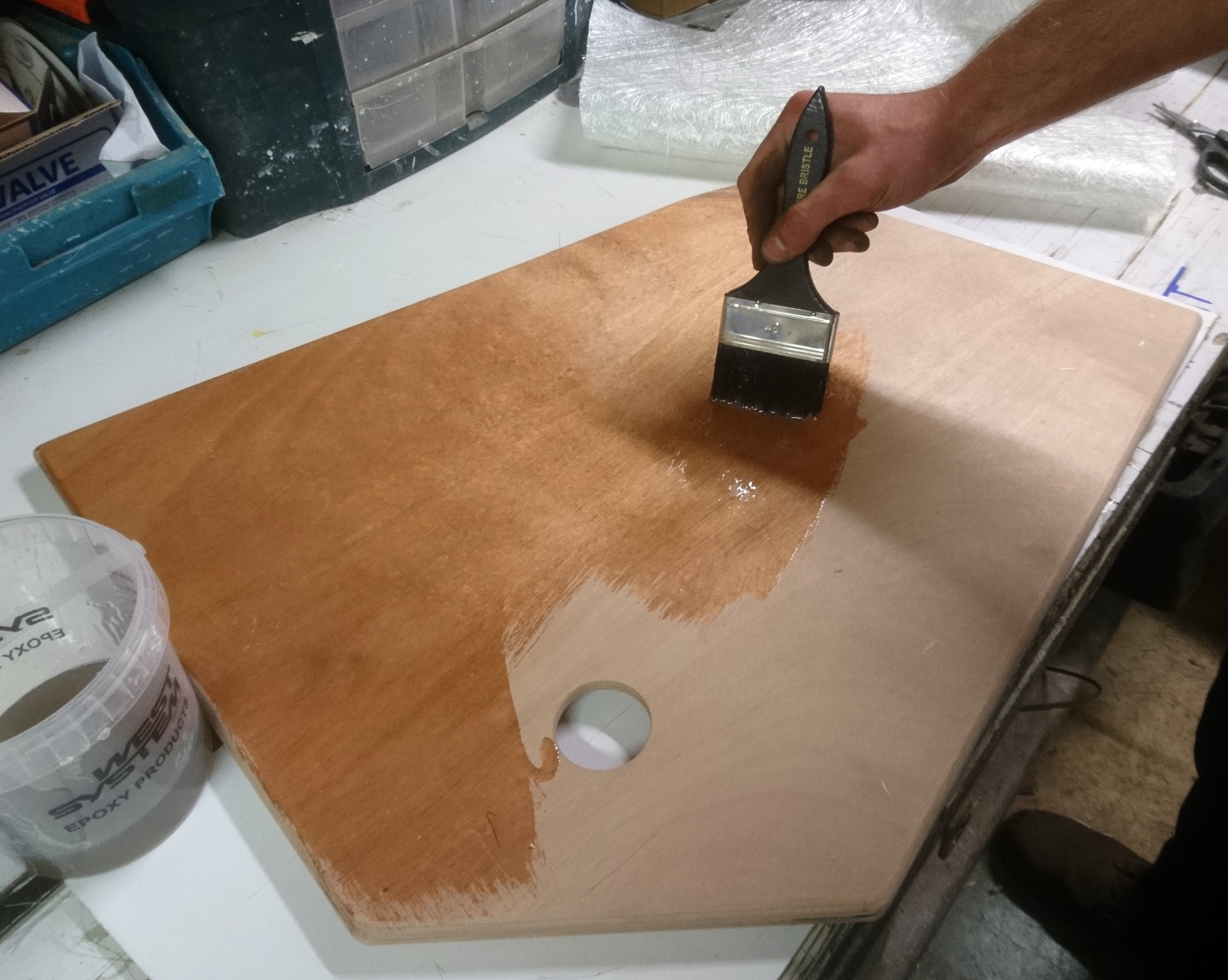
Paint on a coat of resin first.
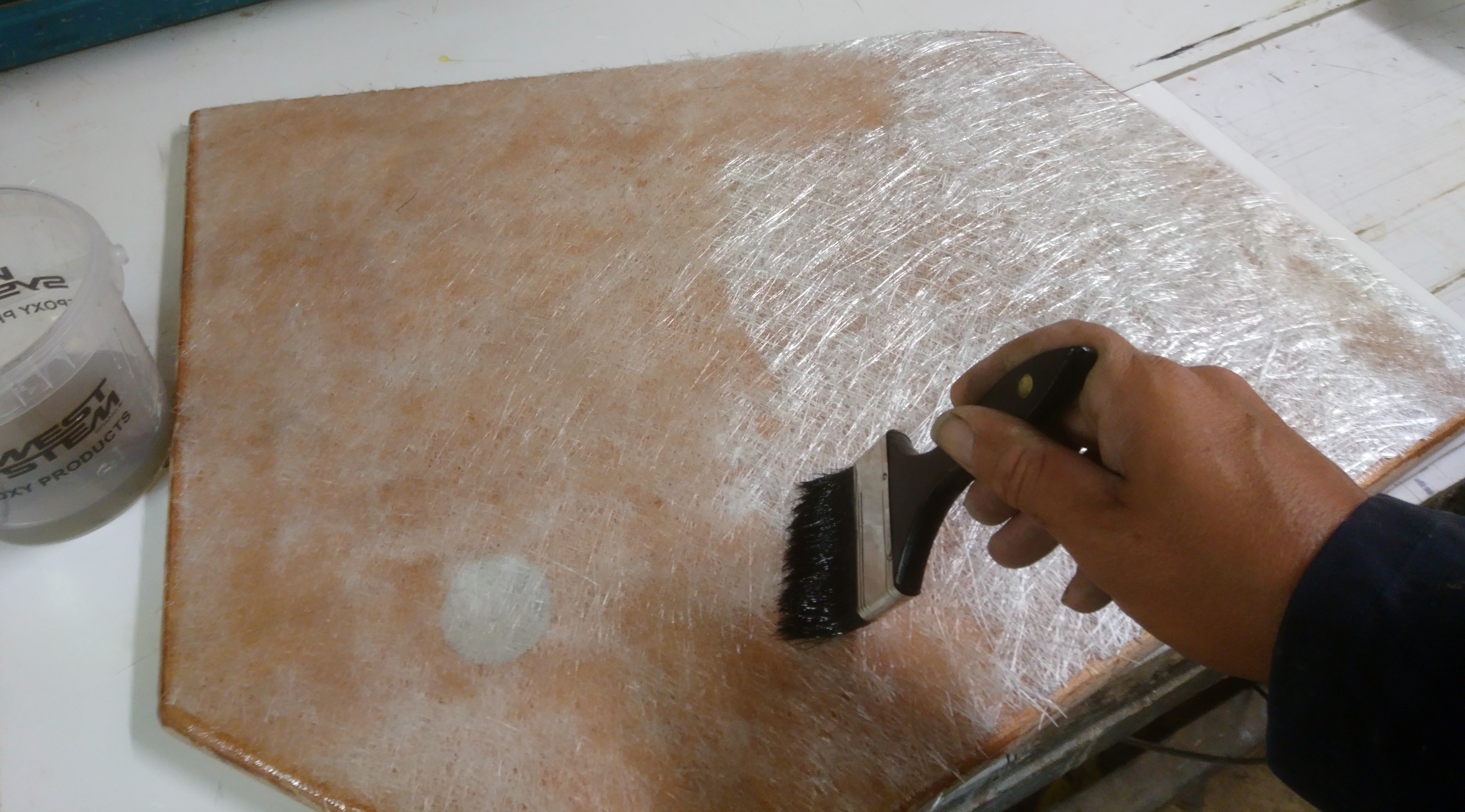
Then lay the first layer of chopped strand mat and wet out with resin.
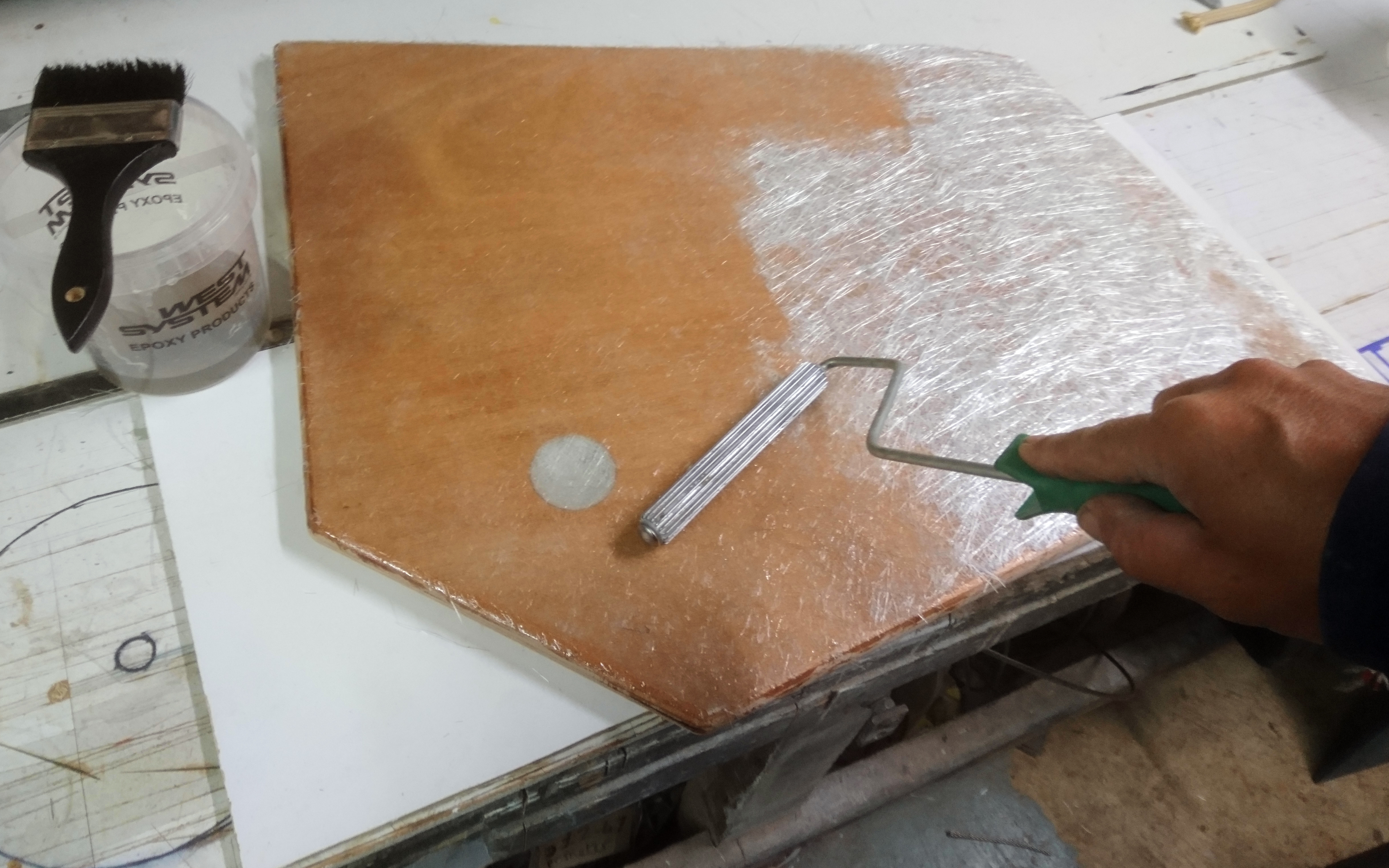
Use a roller to ensure there is no trapped air and is wetted out without using too much resin.
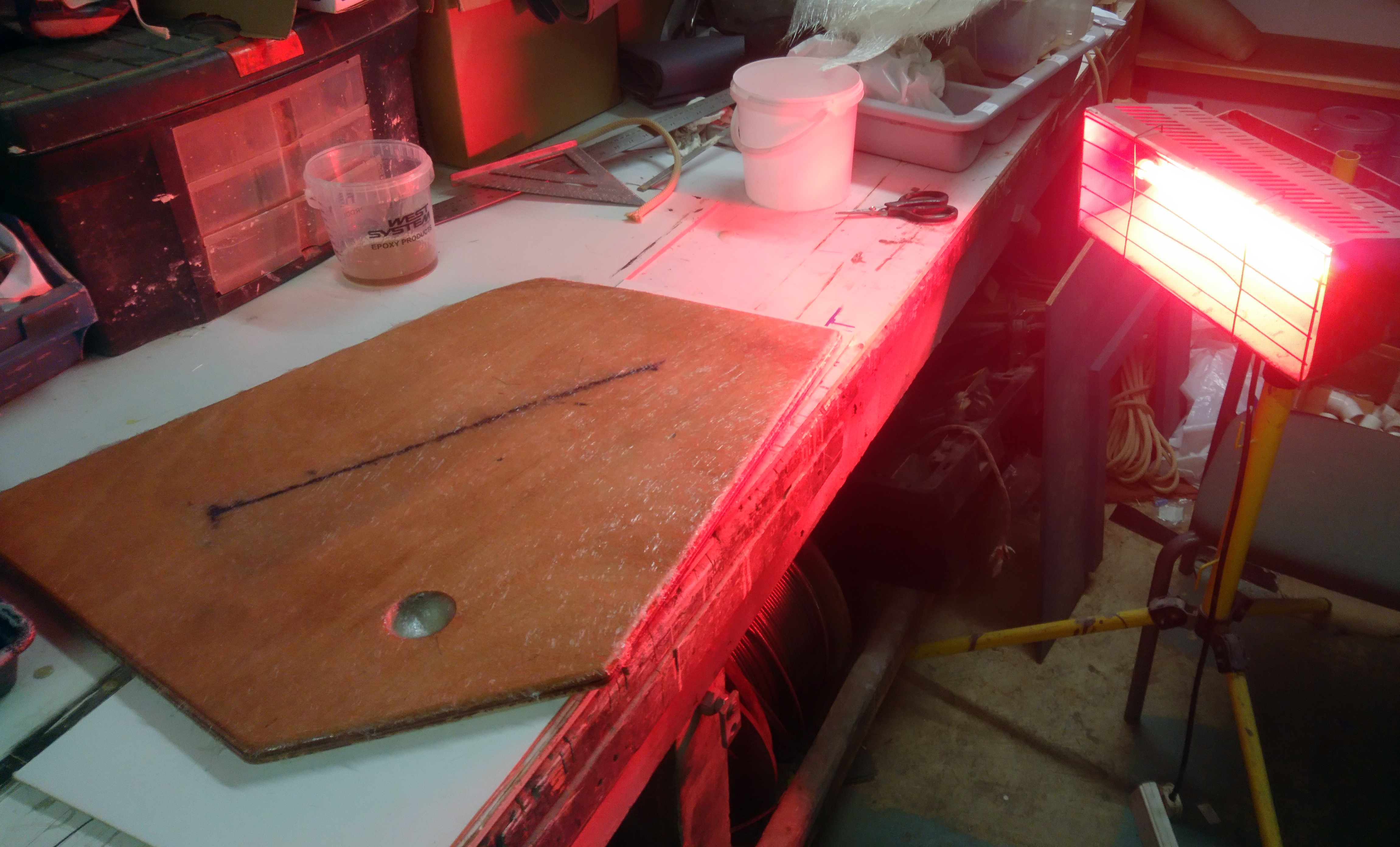
A UV lamp accelerates the curing process
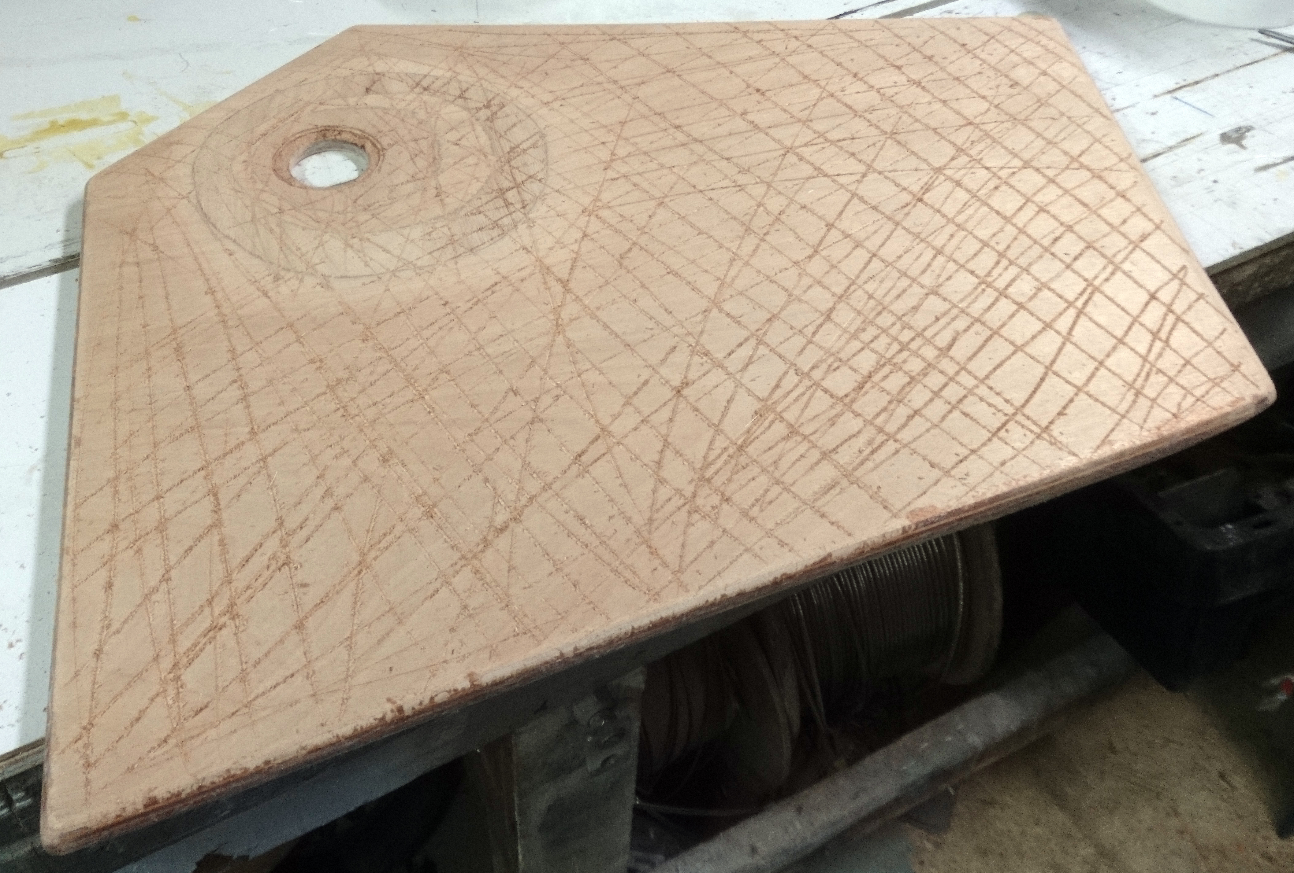
The top surface is heavily scored to increase the bonding strength.
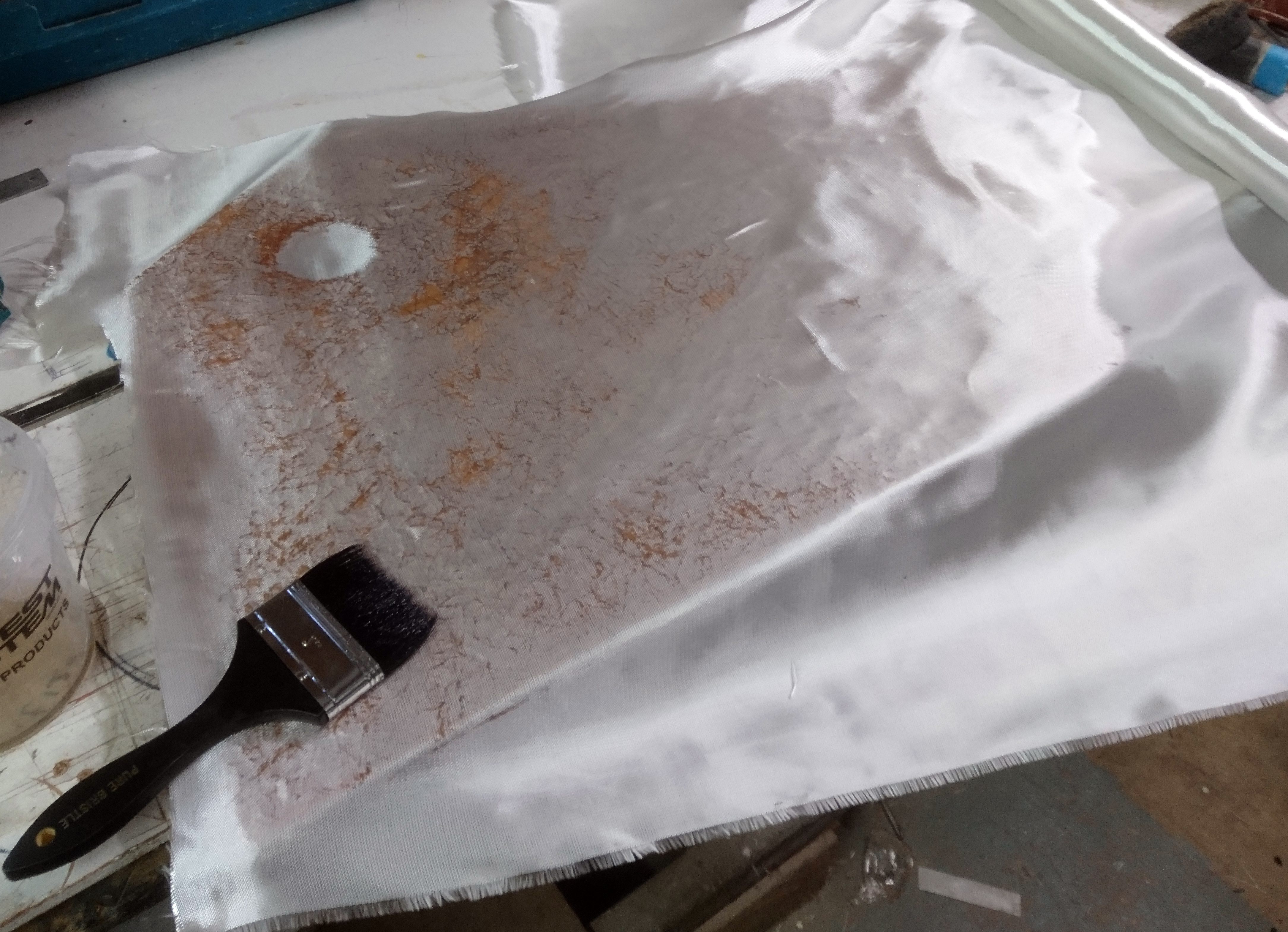
After a layer of CSM a layer of woven cloth can be added.
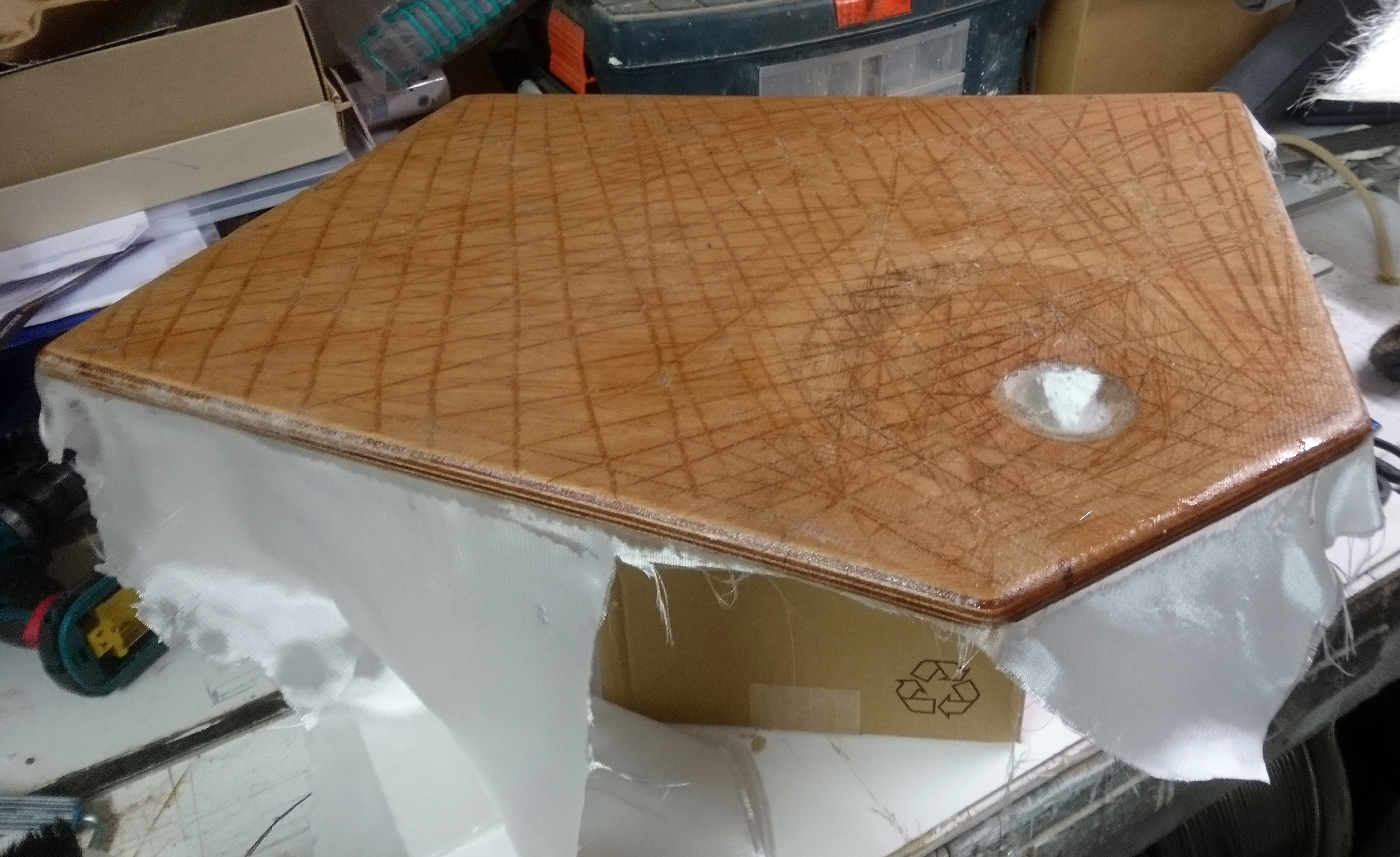
This layer requires less resin as when you use the roller it will pull up surplus resin from the first layer.
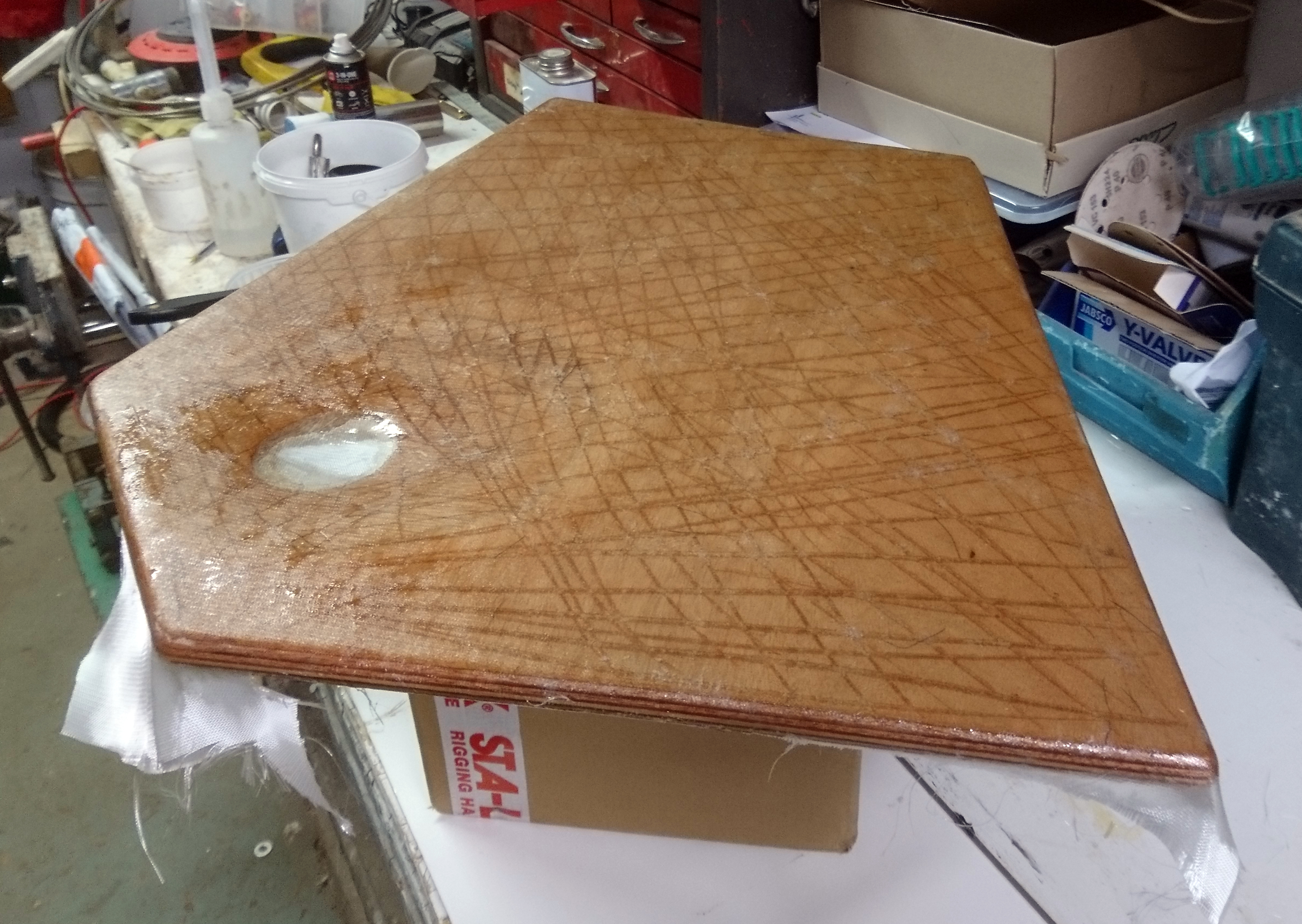
Pulling the cloth down at the edges helps get a good edge seal.
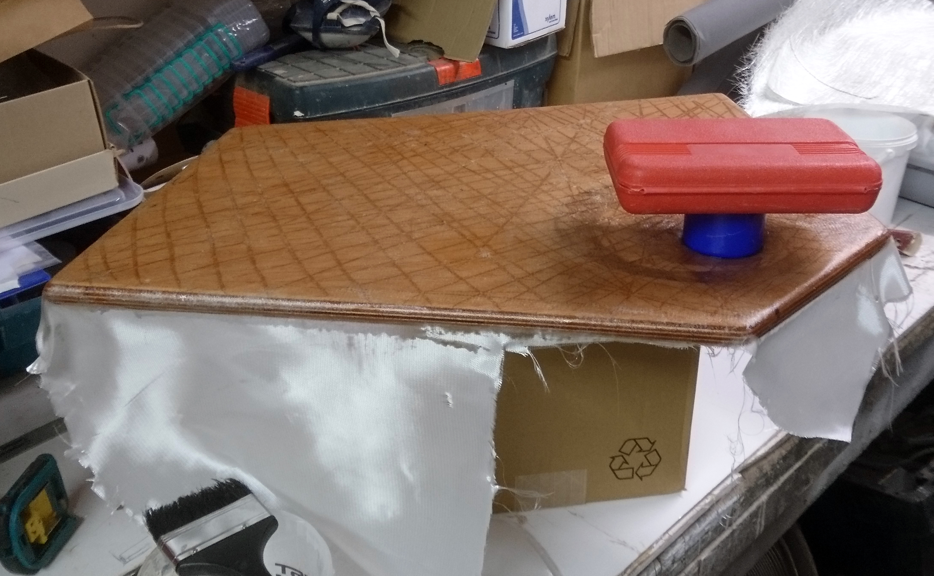
Using a suitable sized “thing” ensures we get a nice clean edge round the drain.
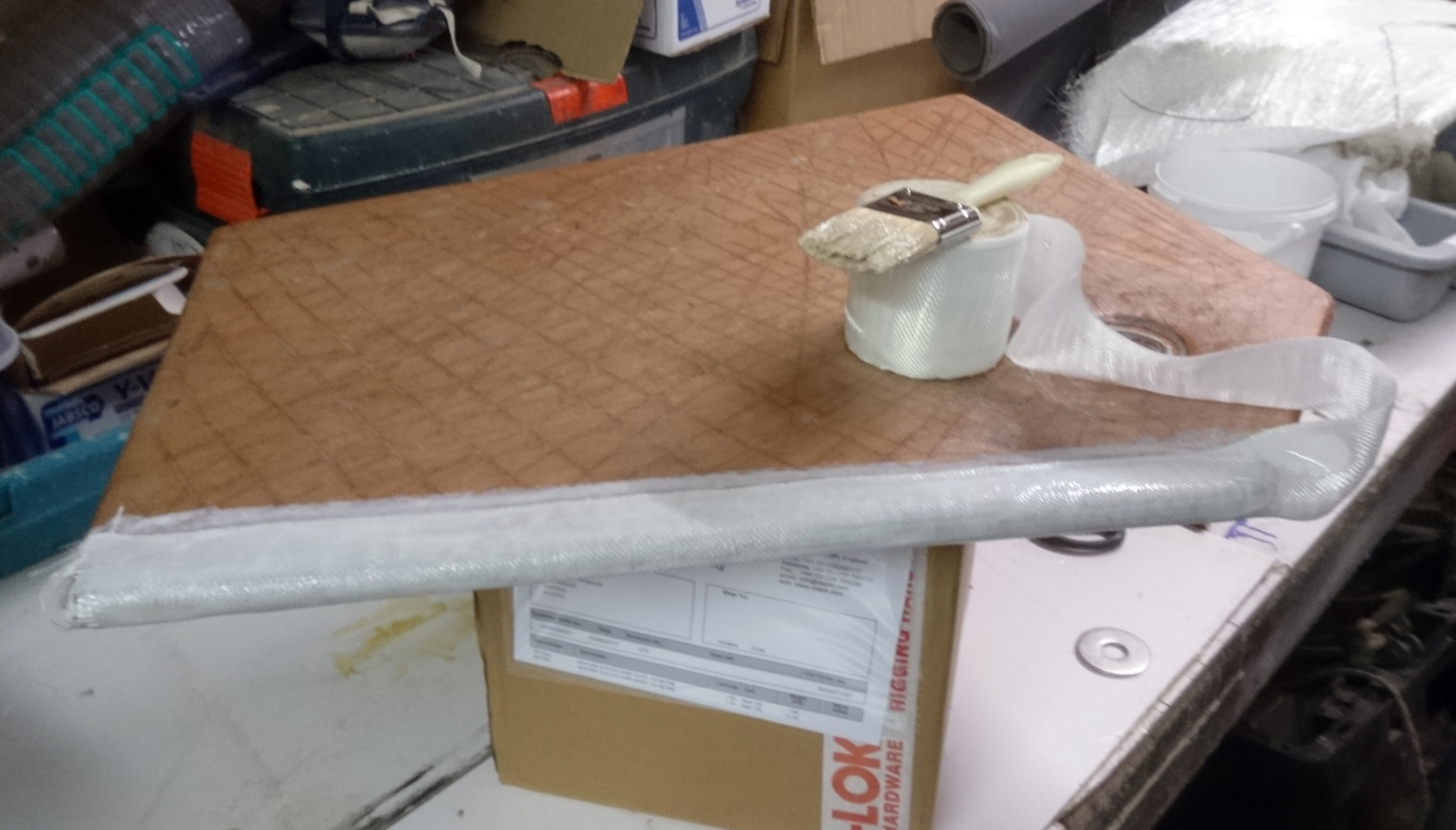
After trimming use 100mm wide tape to seal the edges of the base.
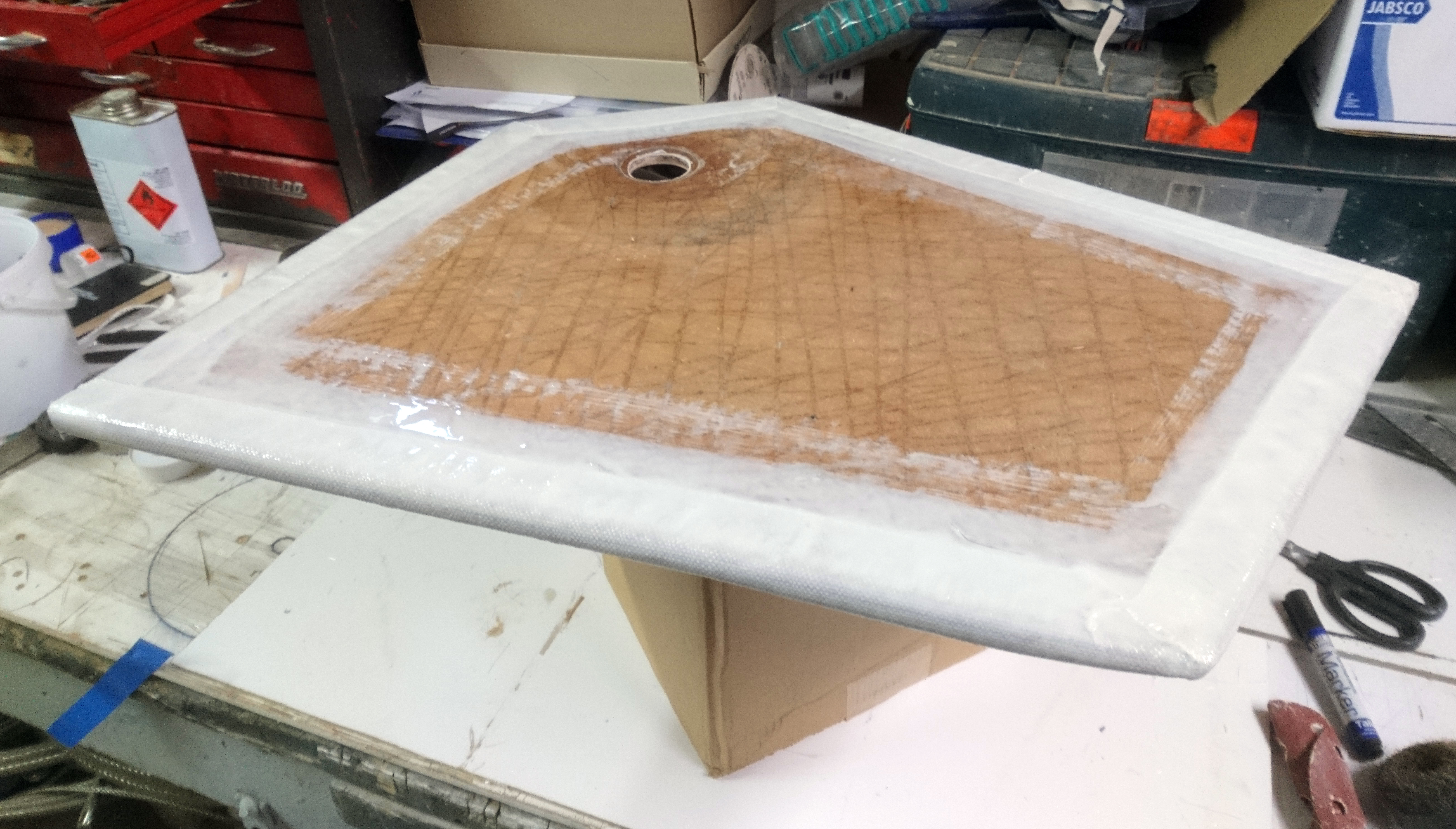
I used slightly pigmented resin for the edges to help distinguish between layers.
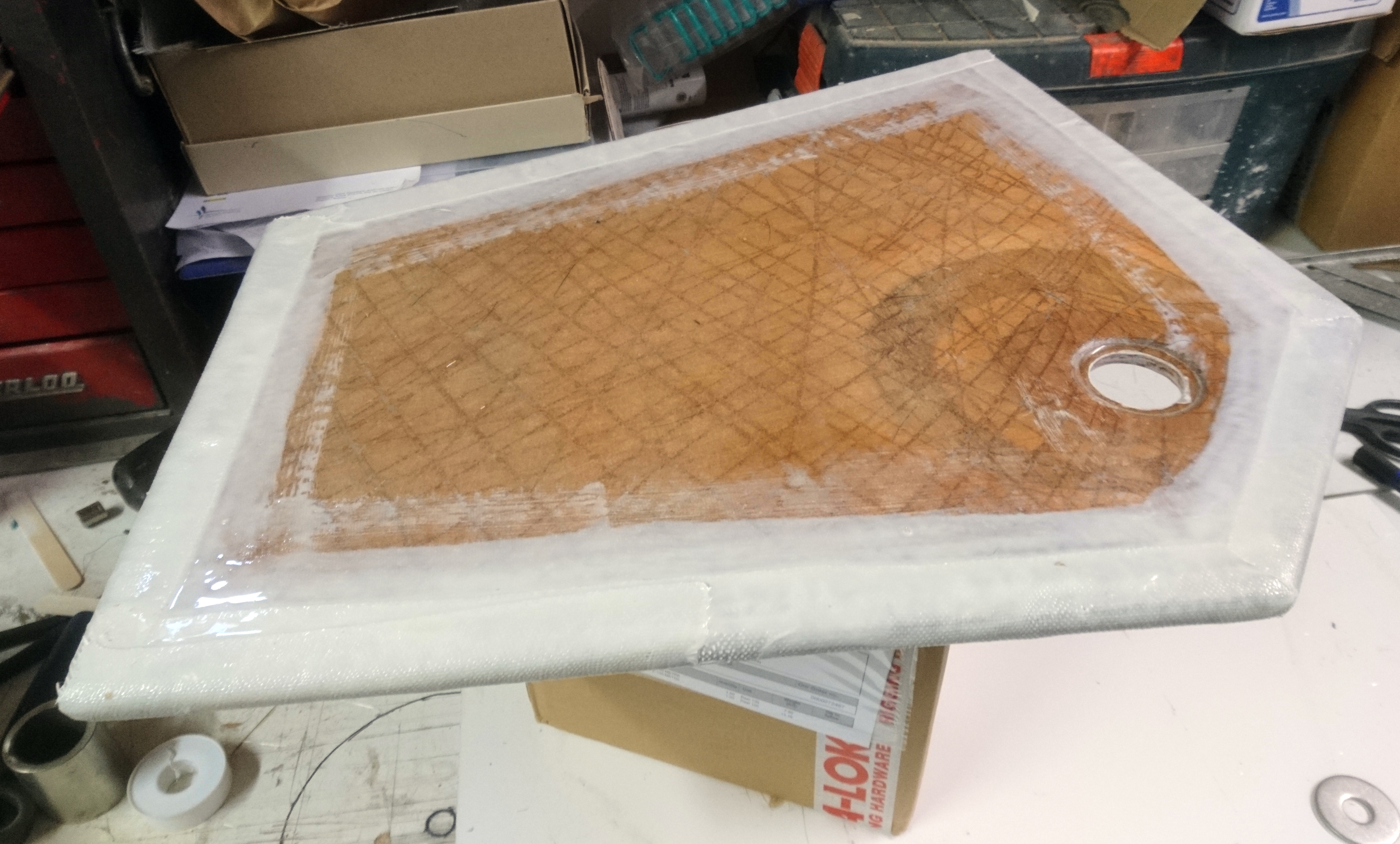
The edges and drain hole are roughly sanded smooth to remove sharp edges and stray fibres.
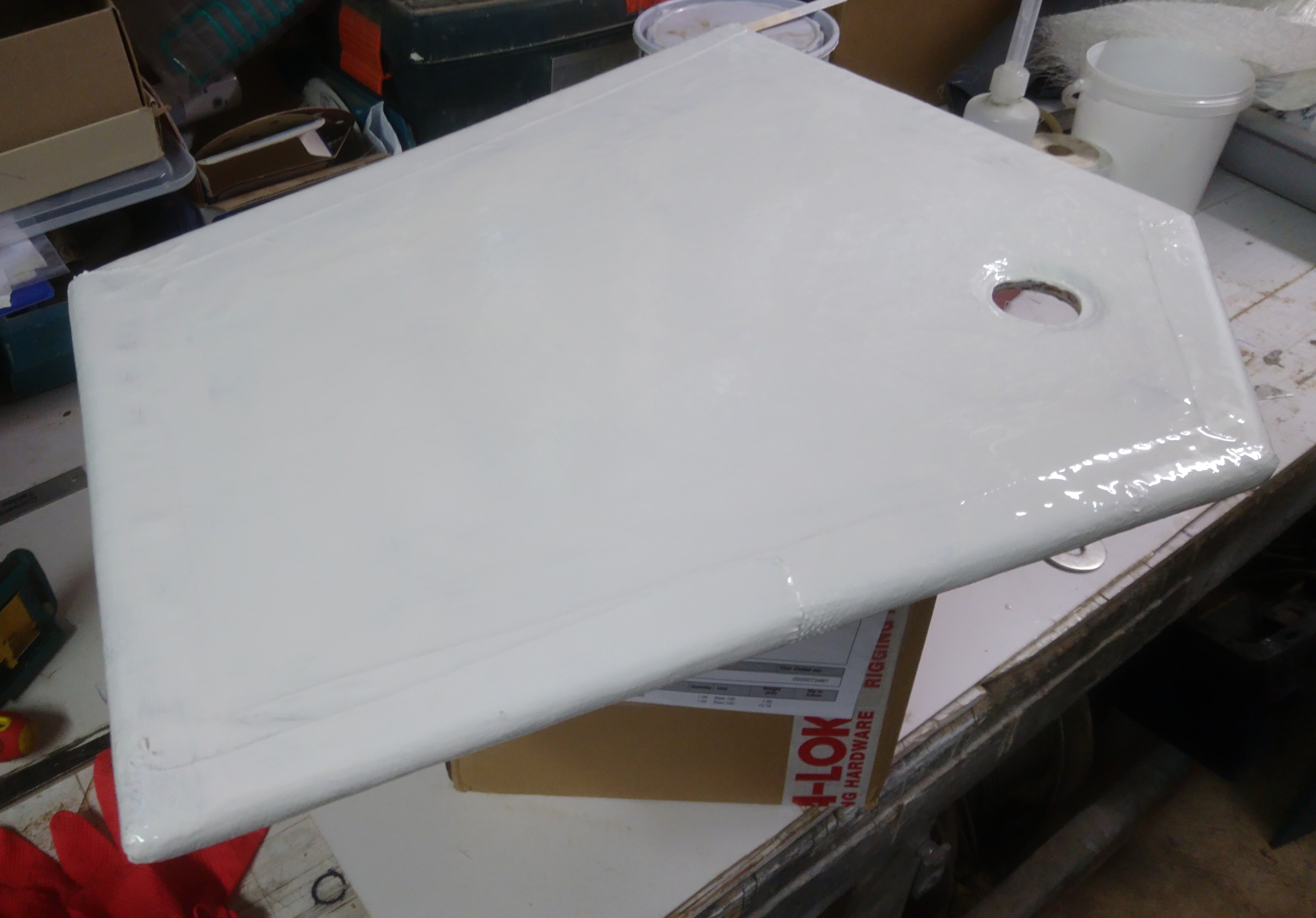
The first of four coats of white gelcoat are applied.
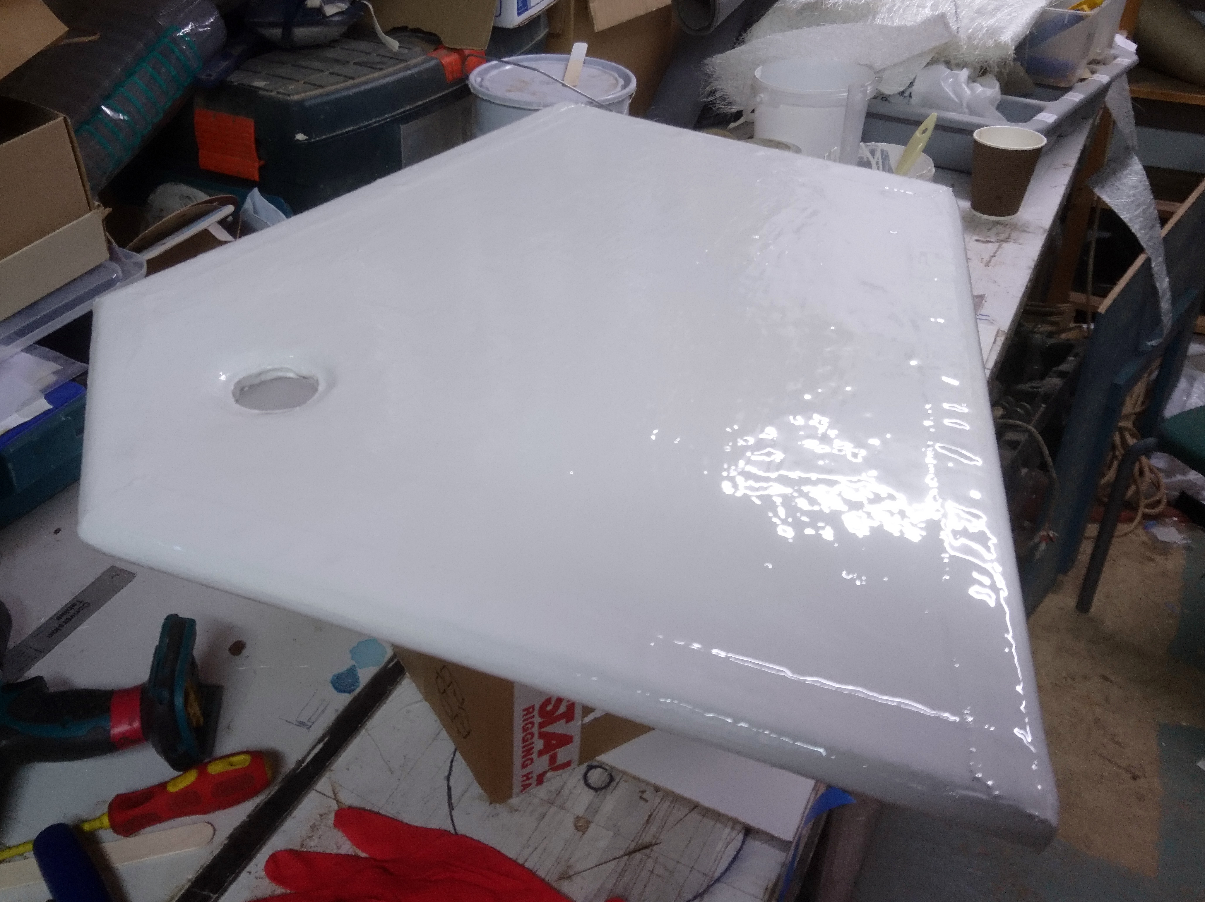
The final coat of gelcoat has wax in styrene added to act as an initial top coat.
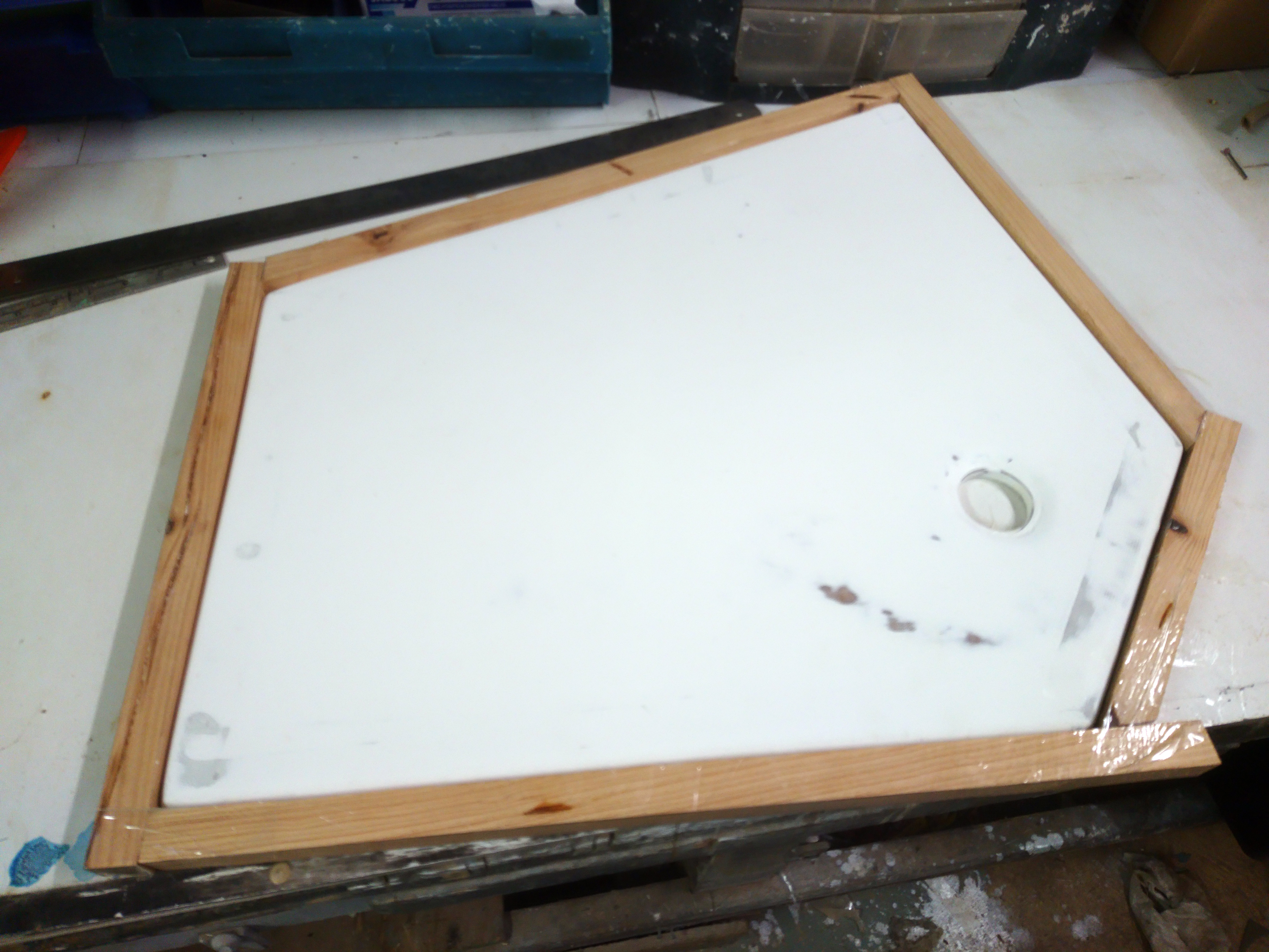
After a good sand with 100grit paper a wood frame with resin proof tape is assembled to allow a sharp edge to be added.
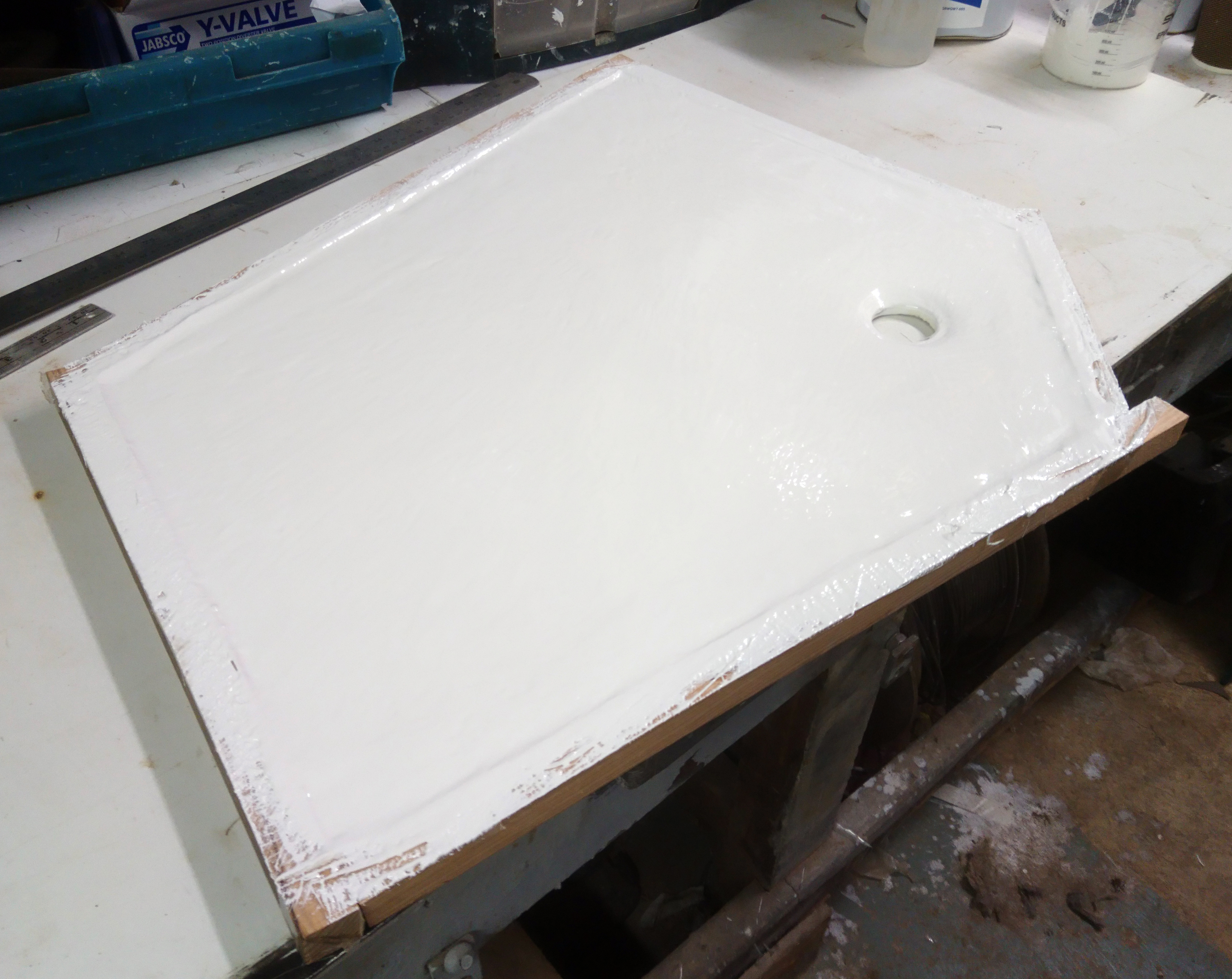
Another three coats of gelcoat followed by another top coat was added.
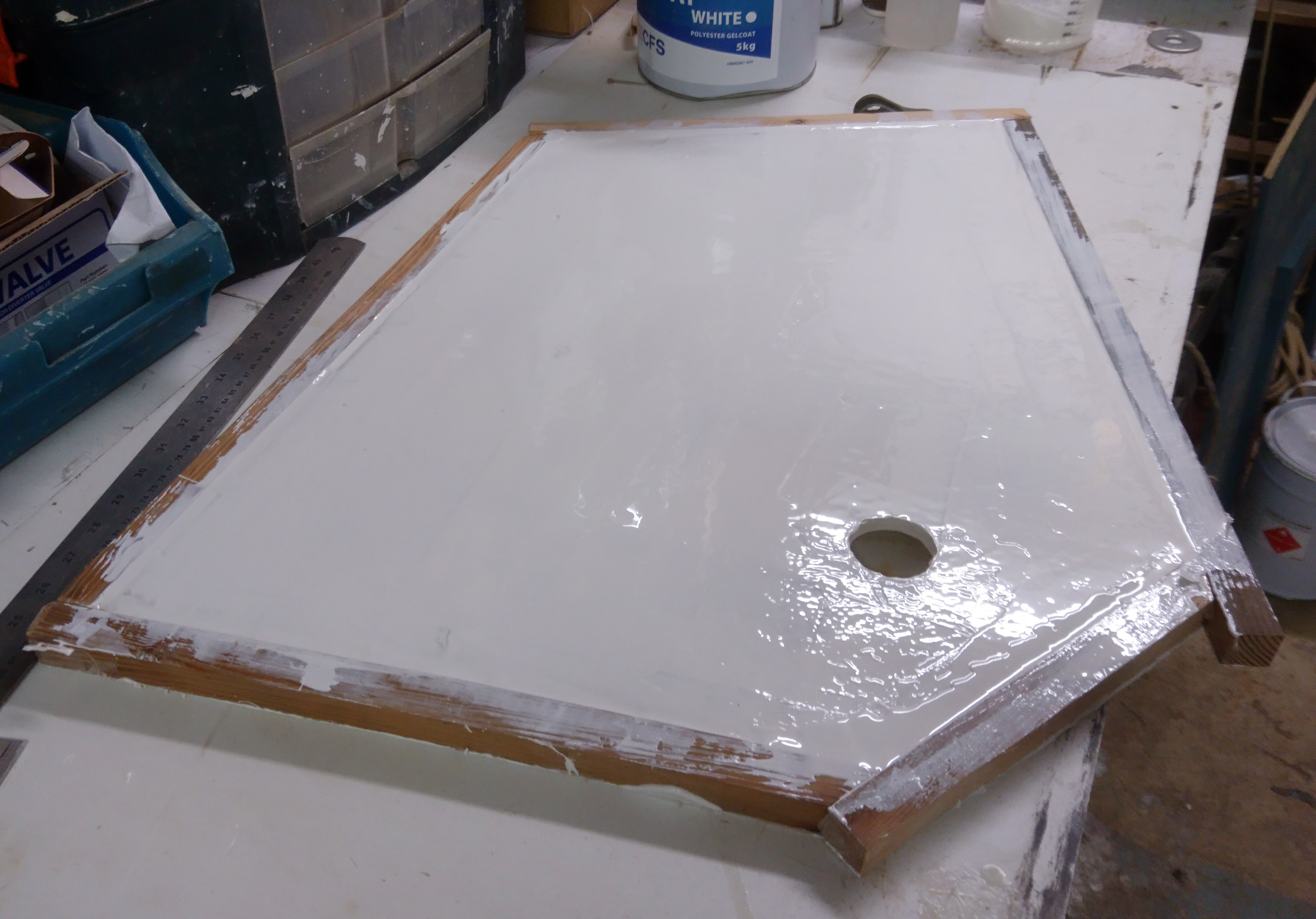
The bottom of the base also had four coats of gel and edges filled.
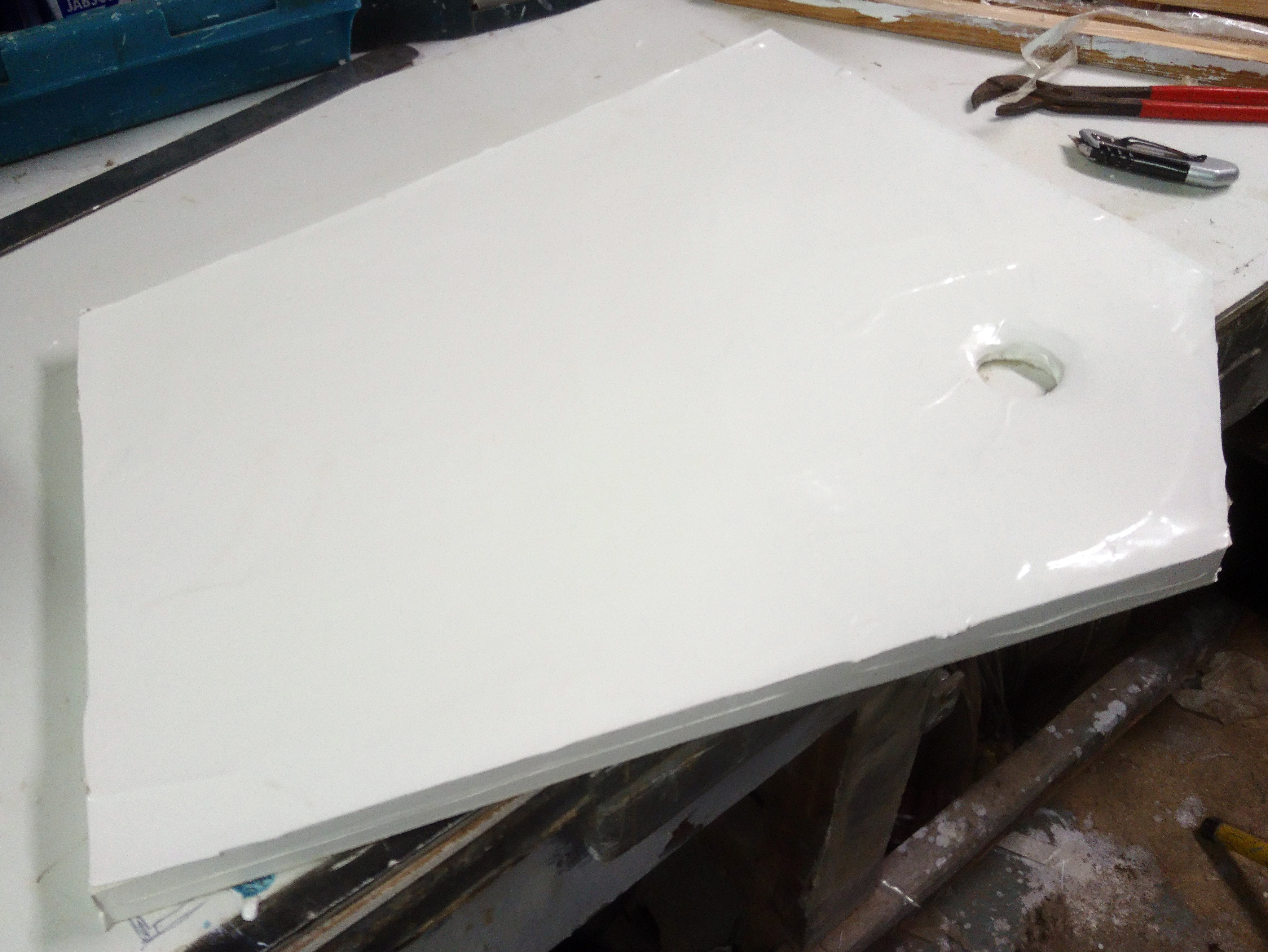
The wooden fram is then removed and the new square edge and be cleaned up as required.
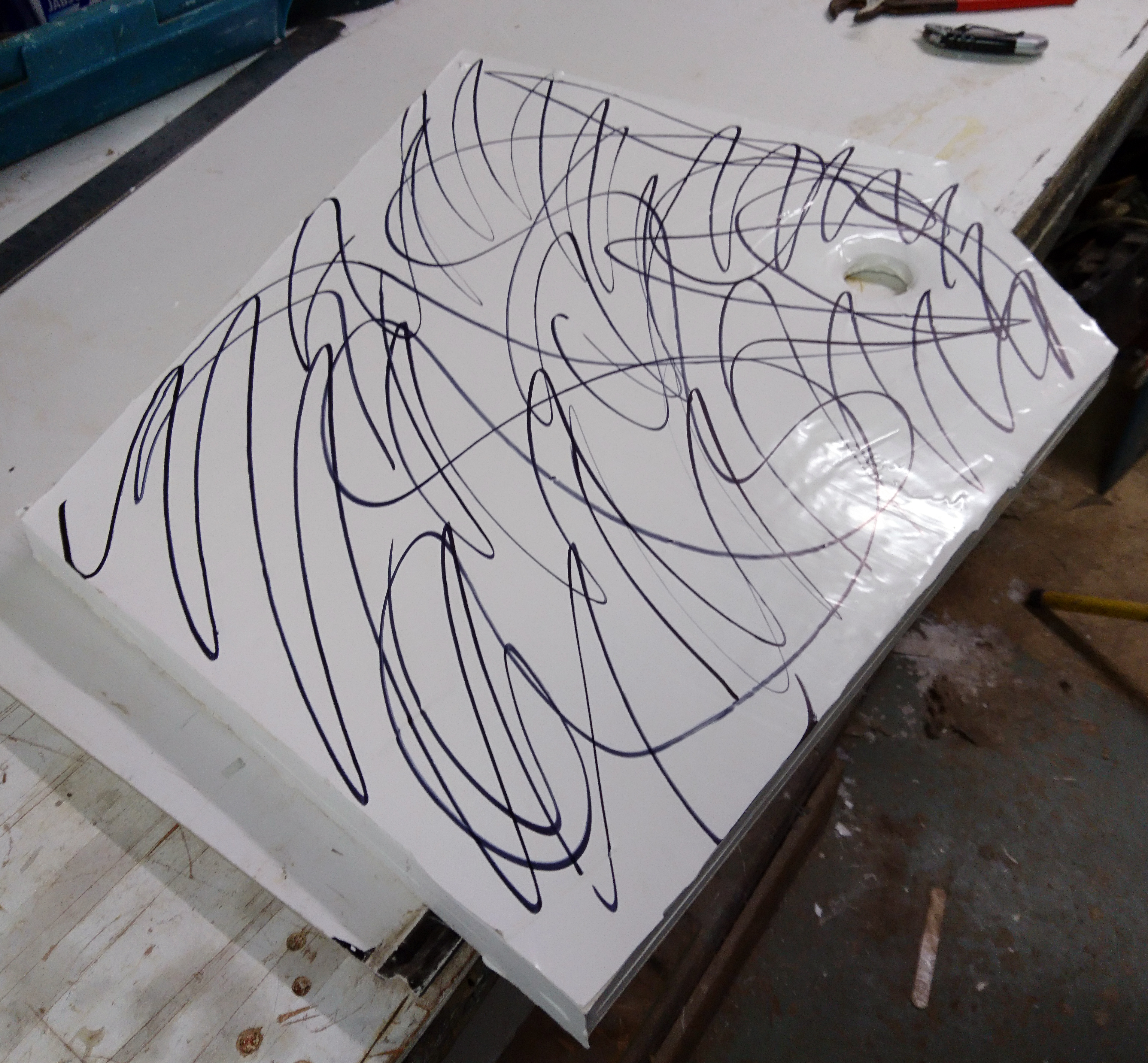
Making the base smooth and shiny starts with 240 grit.
Permanent marker shows low spots during sanding..
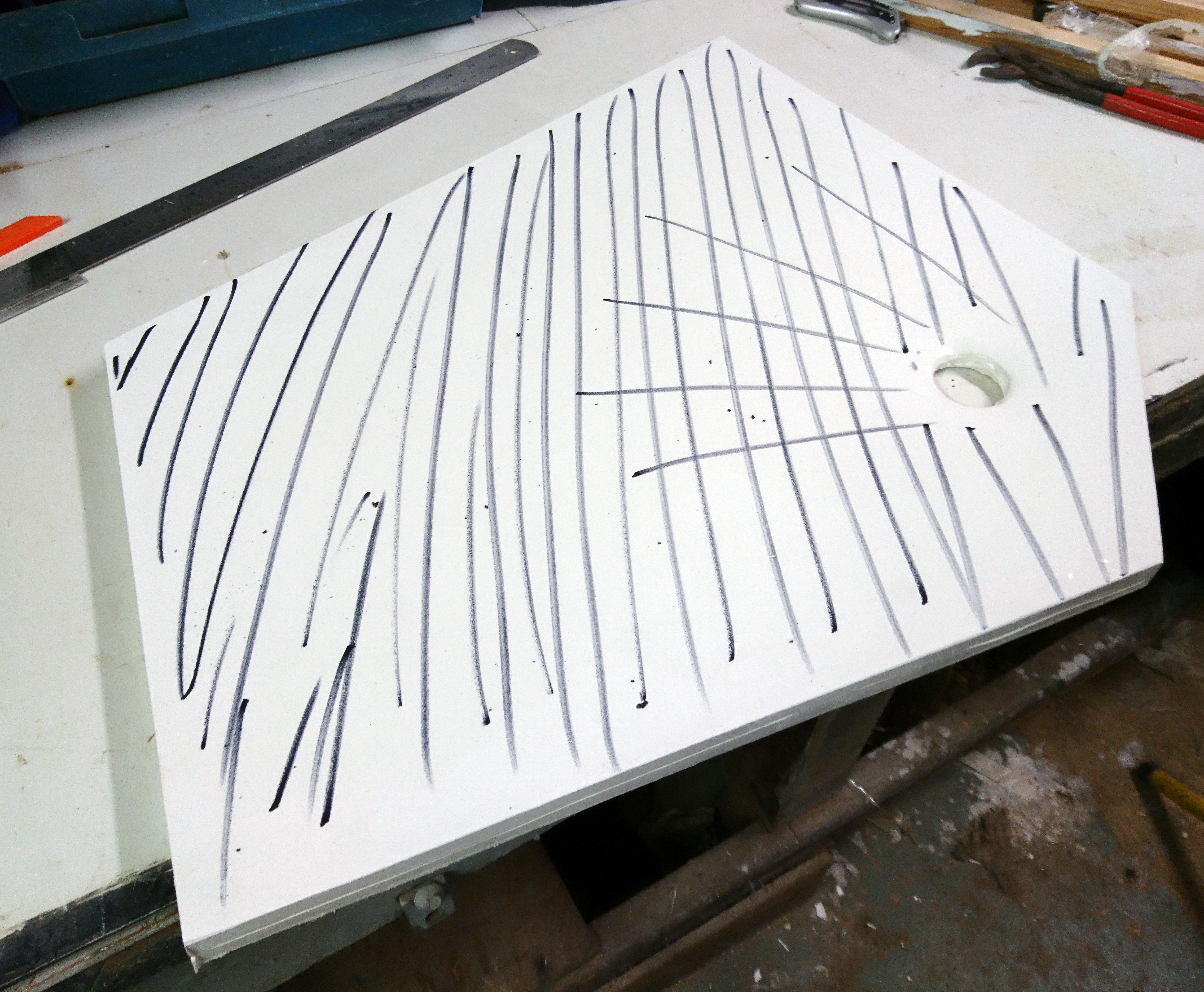
Rinse and repeat through 600, 1000, 1500 and 2000 grit and finish with cutting compound.
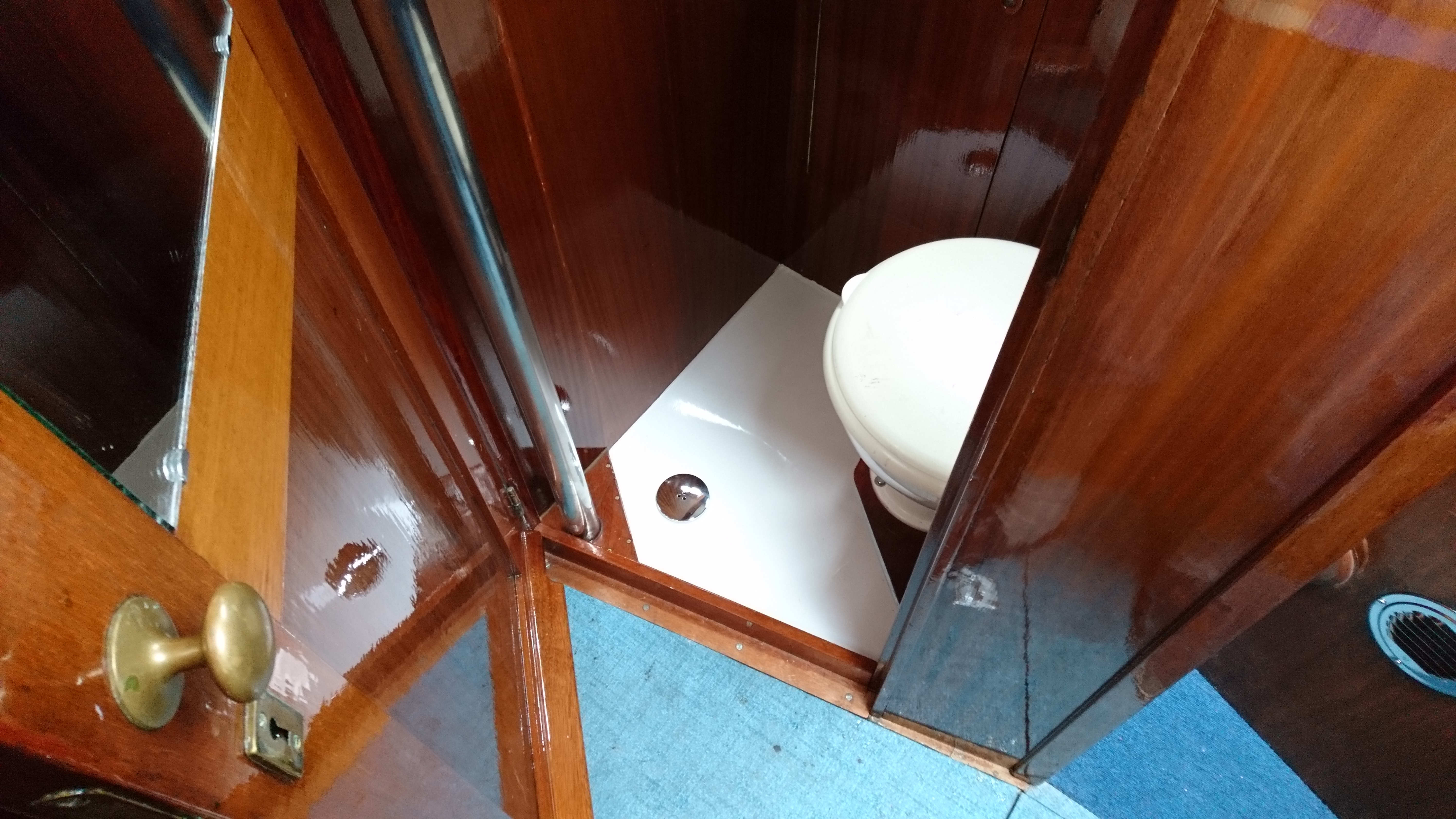
Shower base in position, plumbed in and looking very shiny.