You’ve heard the story before when a guy goes to the doctor for simple pain in the chest that he’s sure is indigestion and ends up with a heart transplant?
Well this story is a little like that and frankly could have ended up just as deadly if no action had been taken.
Firstly I need to apologise for the quality of some of the photos.
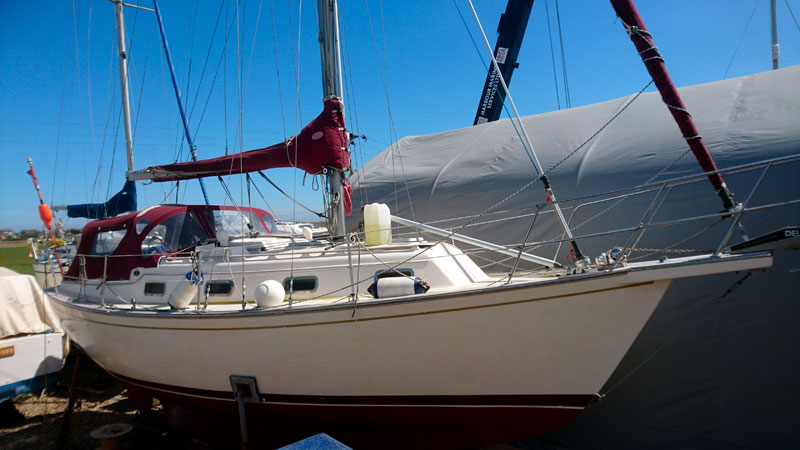
Most were taken down a very dark hole, in the deepest recesses of a Island Packet 29.
A yacht that I had previously held in high esteem, as a “a quality product that won’t let you down, sir”.
From this point on I will not be as generous with my praise about this class.
Anyway the owner had noticed a rumble when under power and we decided that it sounded like the cutlass bearing was on its way out.
We said we’d check it out when the boat gets lifted.
So out she came and sure enough the shaft was wobbling about.
A new cutlass was ordered and an apprentice was instructed to take the prop off, undo the lock screws and pull the cutlass bearing out of the tube.
After a short time the apprentice sought me out saying that one of the locking grub screws wouldn’t come out and “Should the stern tube be wobbling about?”
Now if you happen to own a IP29 and are of a sensitive nature I urge you to grab a stiff drink.
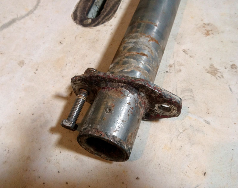
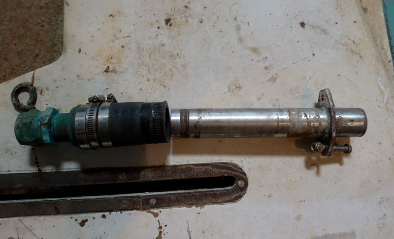
The reason the tube was indeed wobbling about was because there were just two bolts, threaded all the way I might add, with nylock nuts.
No washers, no backing plates.
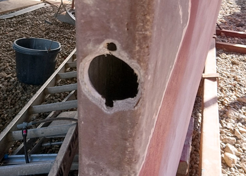
The hollow grp keel through which it was bolted was only 12mm thick, however where the nuts had been tightened they had compressed the grp to such an extent that the lower hole had compressed to nothing.
Not only that but there was no other internal support for the tube, even at the stern gland.
Keep in mind that the 1” dia shaft runs around 5’ between the skeg and the engine coupling.
Having no internal support for the prop shaft tube or shaft is asking for trouble.
In our view, catastrophic failure was only a question of time.
The first indication of trouble would be water in the bilge, which given her design, it would have been quite difficult to trace.
If this were a car, we’d be demanding an immediate recall or at the very least, an immediate inspection.
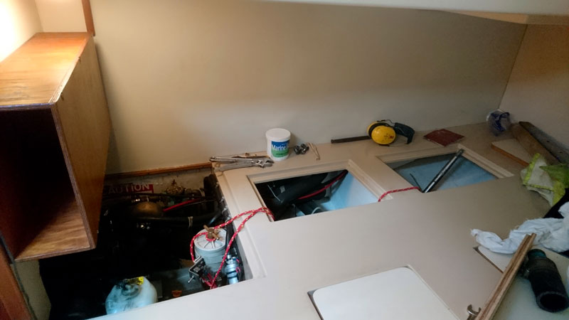
Internal access is achieved through the aft 2 holes under the double Quarter berth.
The forward big inspection hatch allows access to the rear of the engine and gearbox coupling.
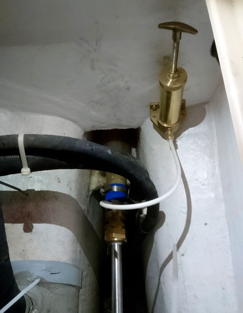
The middle hatch allows acces to the stern gland and greaser.
The aft hatch allows acces to the aft of the keel and the exit of the propshaft tube.
You can’t remove the propshaft from the boat aft as the rudder is in the way.
There is also no room to take it forward as you can’t get it past the engine.
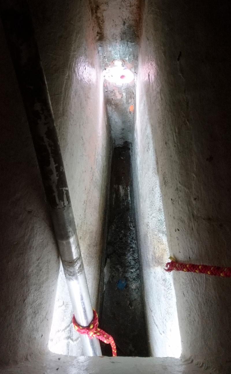
We did find that we could manoeuvre one end down into the bilge and the other end poking out of the aft hole.
The red rope is there to hold the propshaft in place whilst we effect the repairs.
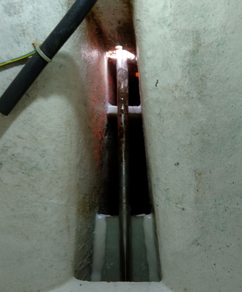
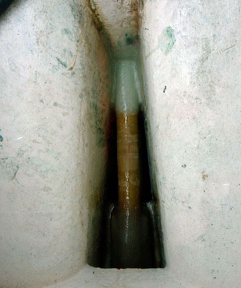
The next image was taken looking down and aft.
The keel is around an arms length deep and no more than 3” wide at the bottom.
You can see there is no support or even any localised strengthening around the propshaft exit hole.
An update to now worried/relieved owner, a bit of head scratching and we arrived at a plan.
One of the first jobs was to clean all the crud and mud from at the bottom of the keel, now where did that apprentice go…..
I decided to make a dam at the back of the keel up to 10mm below the exit hole and around 200mm forward.
Obviously this will live in the bilge so whatever we put down there would need not to rot, so plywood was ruled out.
Even sheathed ply will rot given the slightest hole in the sheathing.
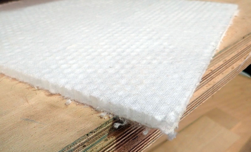
So I used my favourite core material.
Nidaplast is a plastic honeycomb with a bonded scrim on each side.
It comes in various thicknesses from 5mm to 90mm.
I mainly use 10mm or 15mm as this tends to be the same thickness used for the balsa core in decks.
A couple of layers of 250g woven cloth glassed on each side results in a panel as stiff as plywood at around ¼ of the weight,
with of course the added benefit that it wont rot.
I epoxied a panel vertically into place and a couple of feet forward I epoxied in another Nidaplast panel, which would act as a shelf to take the load of the front of the new shaft tube and stern gland.
Just to make life awkward, we had to relocate the propshaft into its usual orientation, as if dangling upside down, in a small hole, with just enough room for one arm and my head was not hard enough.
You just have to love this job sometimes………
The void aft of the vertical panel was filled with Pro-Set expanding closed cell foam.
This foam is much, much stronger and stiffer than the usual builders merchant expanding foam and it also has very good bonding performance.
Closed cell is again important as it won’t absorb any water.
Once the foam had set hard it was trimmed flat and I applied five layers of 450g woven cloth on top and round and down the front of the panel.
Note I’d taped the propshaft to make it easier to remove any epoxy afterwards.
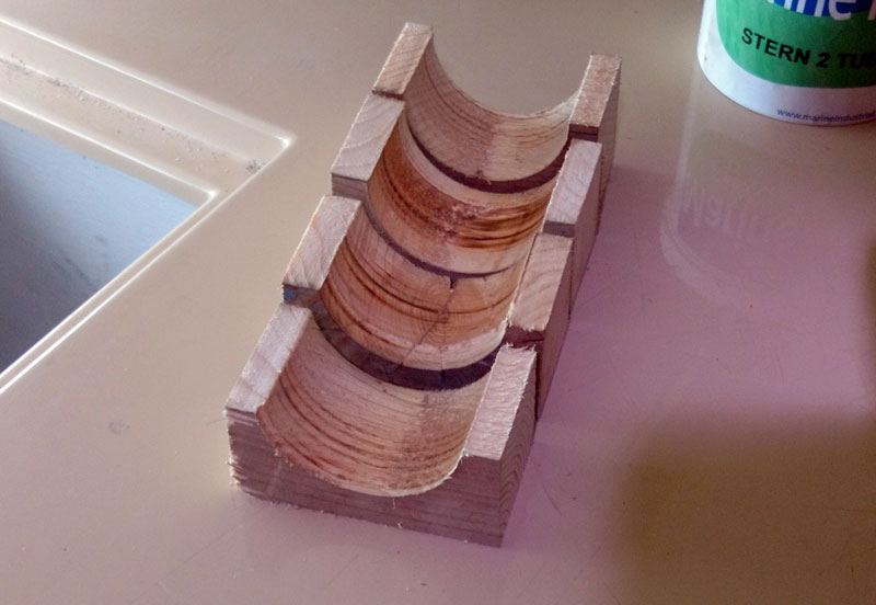
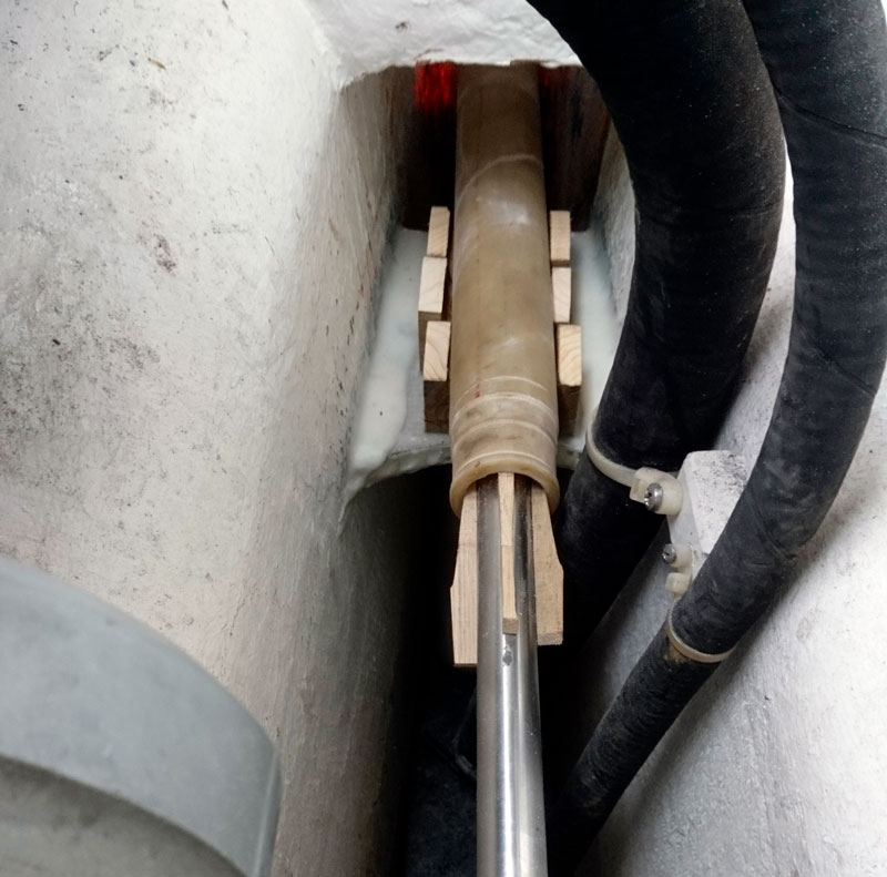
Next we made some tube supports out of softwood with the plan that these would sit on the new shelf and support the new grp propshaft tube.
Note the wooden wedges stuck up the tube to keep the propshaft central to the tube.

It’s at this point its essential to ensure we have perfect alignment.
So the propshaft was re-attached to the gearbox coupling and outside we chocked the propshaft so that it exited the keel exactly central to the exit hole.
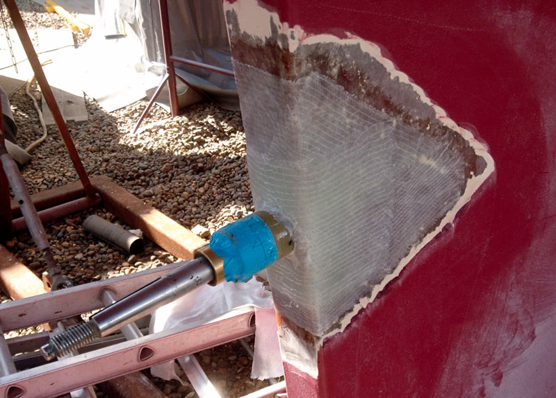
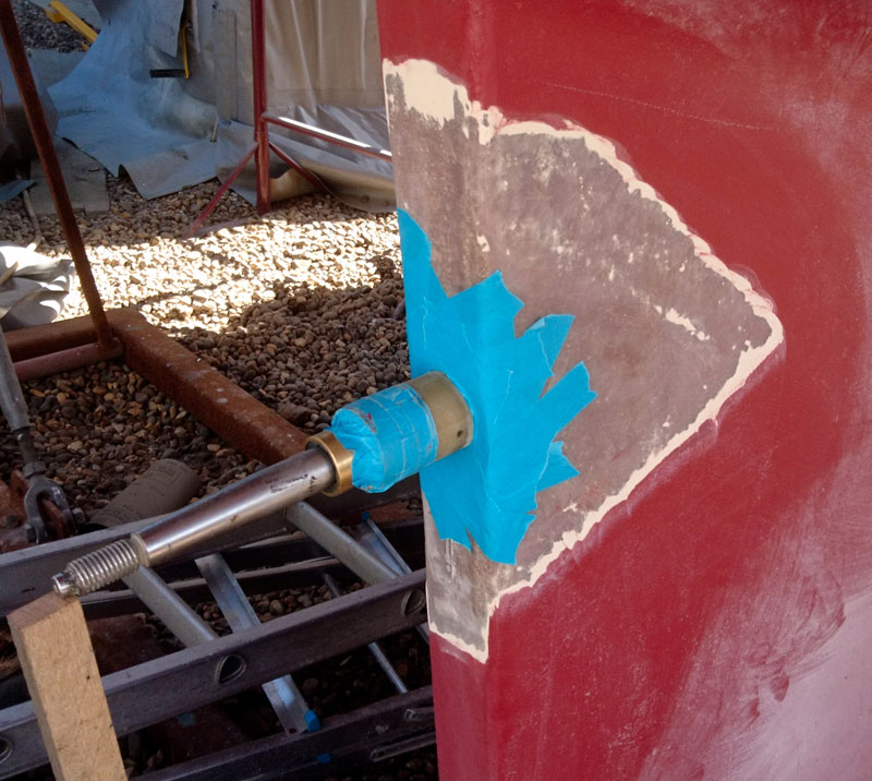
Once this had been achieved and chocked into position I taped up around the sterntube on the outside to stop any glass and resin from the inside leaking out.
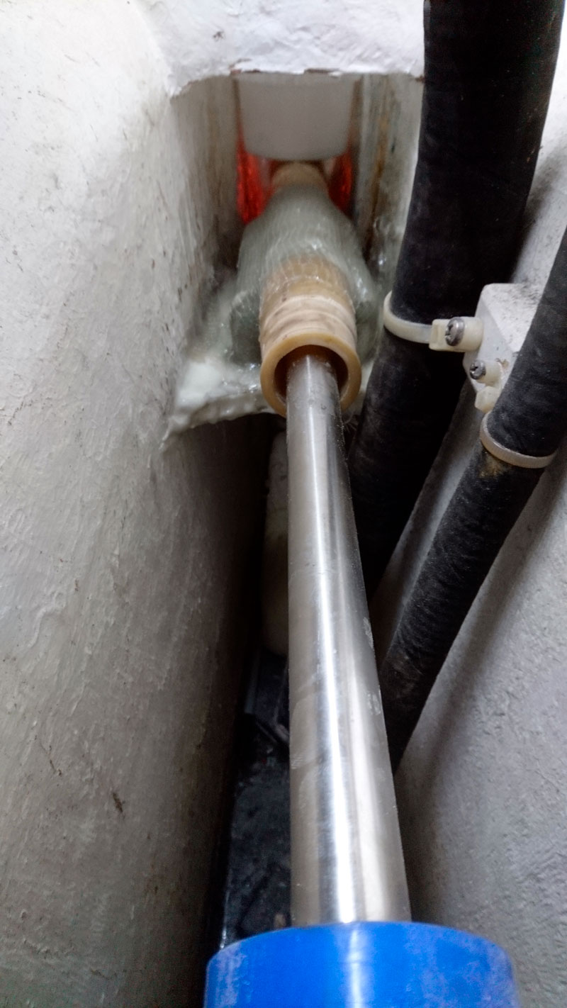
Back in my hole again I injected some thickened epoxy under the tube with a large syringe and then glassed the tube into place, using a mixture of 250g bi-axial and some 450g heavy weave cloth.
After checking the shaft alignment was still ok, I glassed in the front tube supports and sterntube into place.
Again mainly using 250g bi-axial but around the wooden tube supports I applied a couple of layers of 300g powder bound chopped strand mat.
Note that you must only use powder bound csm with epoxy resin as the usual chopped strand mat (csm) is emulsion bound and the styrene in Polyester resin dissolves the emulsion. Epoxy will not dissolve the emulsion in standard csm, so if you use it you can end up with a very sticky mess.
Once the glass had cured we could fit the new sterngland and greaser and thankfully I could exit the hole.
Outside, I’d already ground back the keel and so after a dust off applied five layers of 250g bi-axial cloth.
Once this had cured it was keyed and a couple of coats of epoxy two pack primer was applied followed by a tie coat and then antifoul.
I still shiver at the thought of the owner, sailing out at sea with his youngster not realising he was sailing a sinking timebomb.
