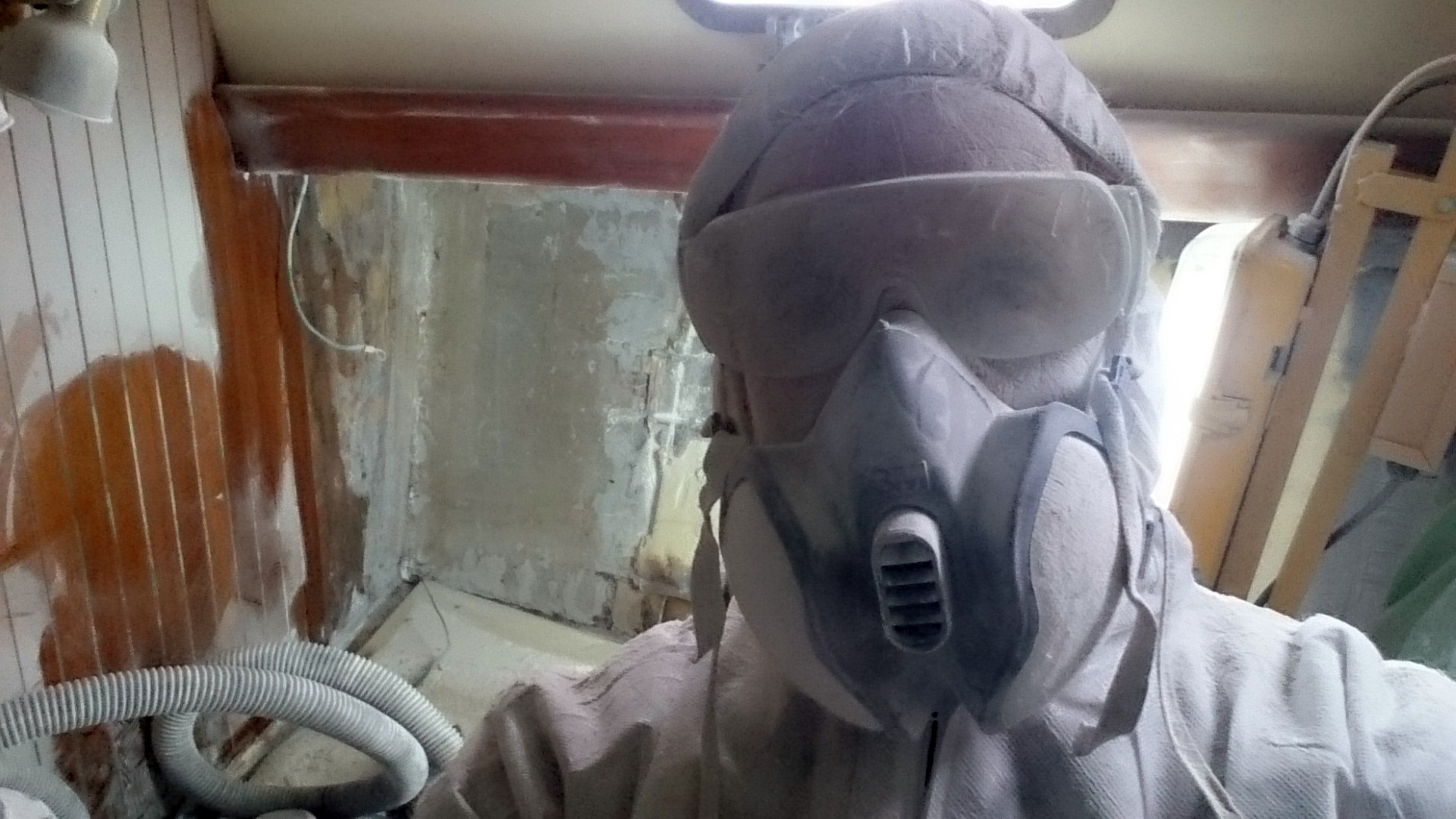
Admin

/Admin

About Admin

This author has not yet filled in any details.
So far Admin has created 19 blog entries.

Compression Post

Compression post repair on a Seamaster 925 – Job Finished –

Whilst doing a little research before starting a new project on a Seamaster 925, I found a quote;
“Holman and Pye design, Seamaster build quality, what more could you ask for?”
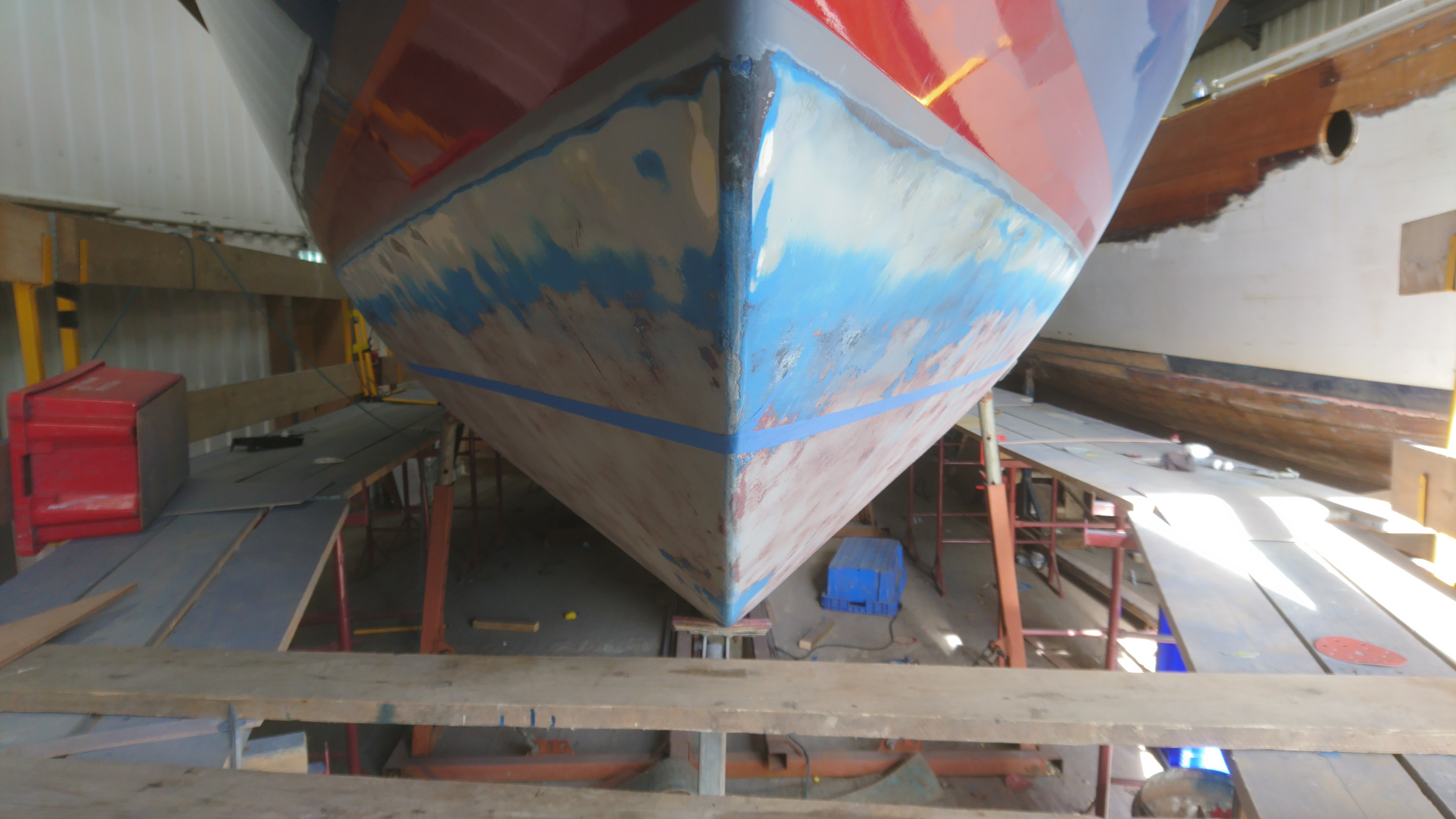
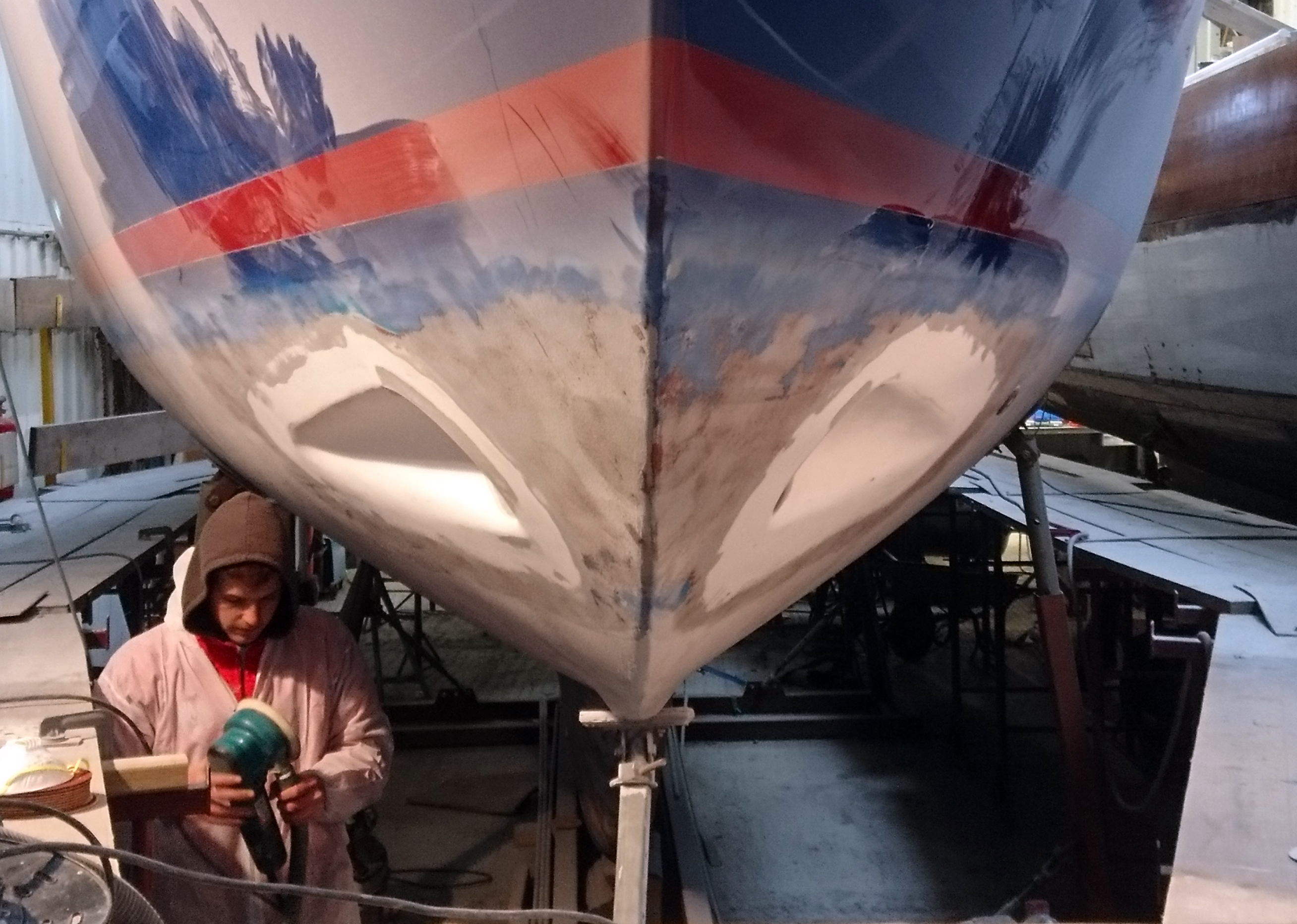
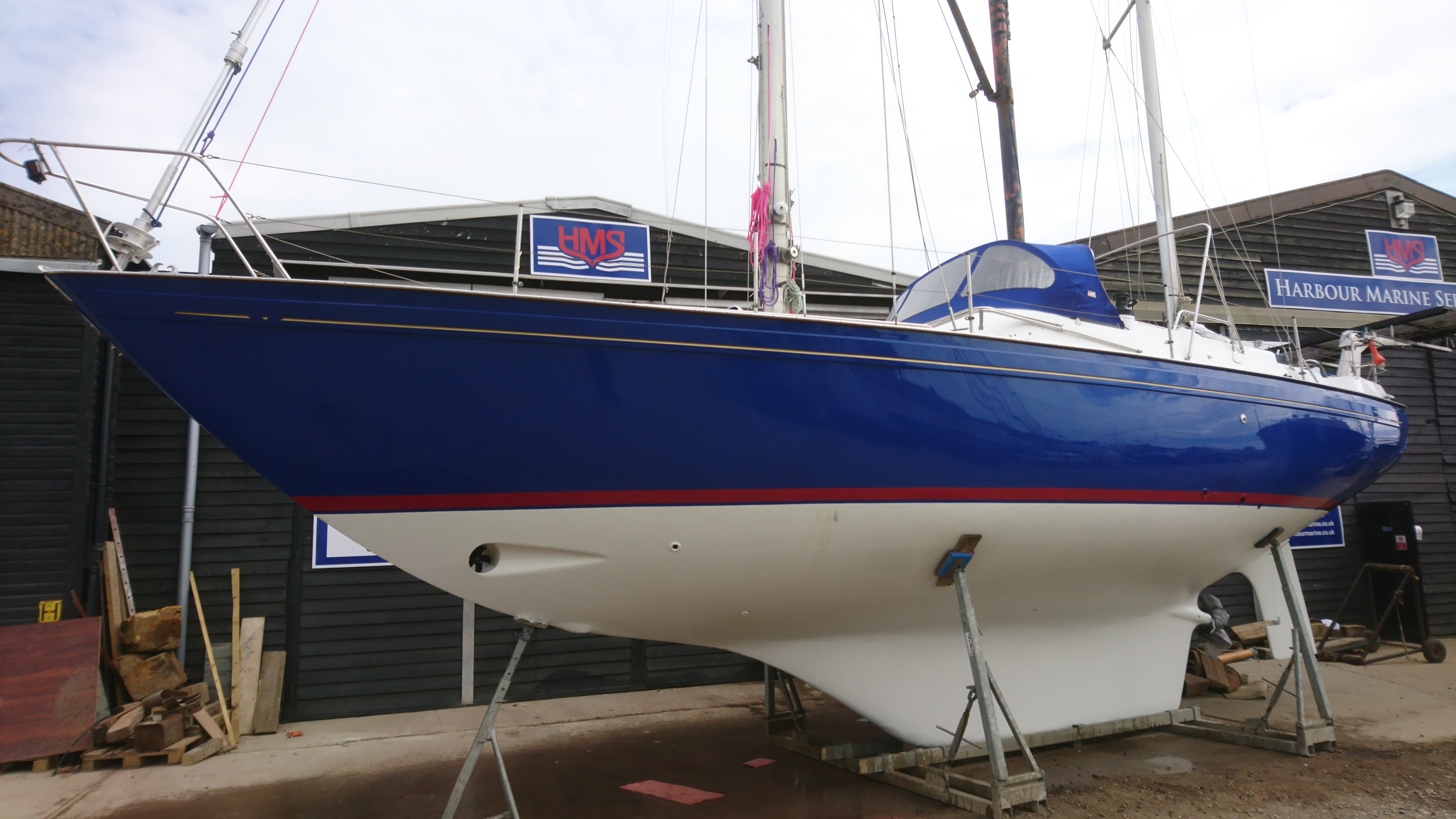
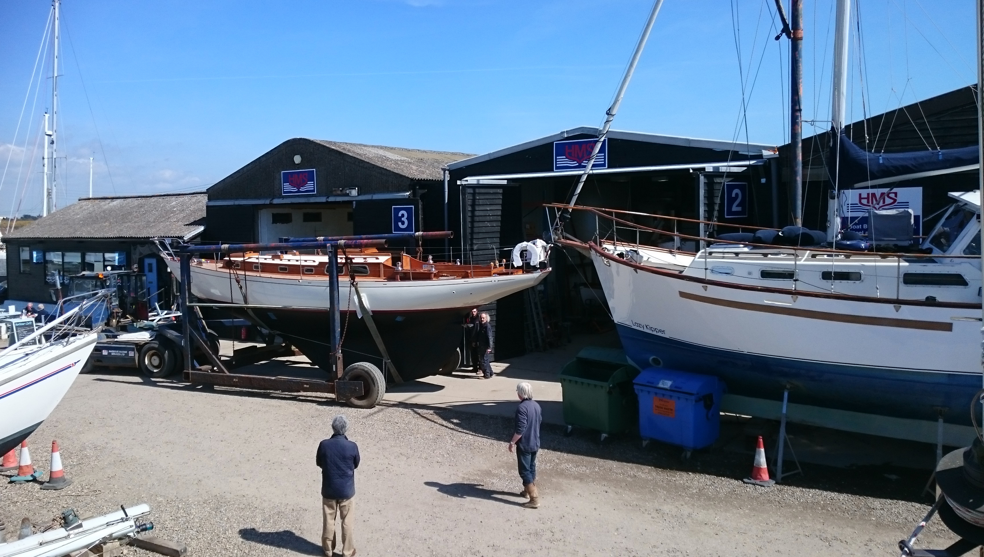
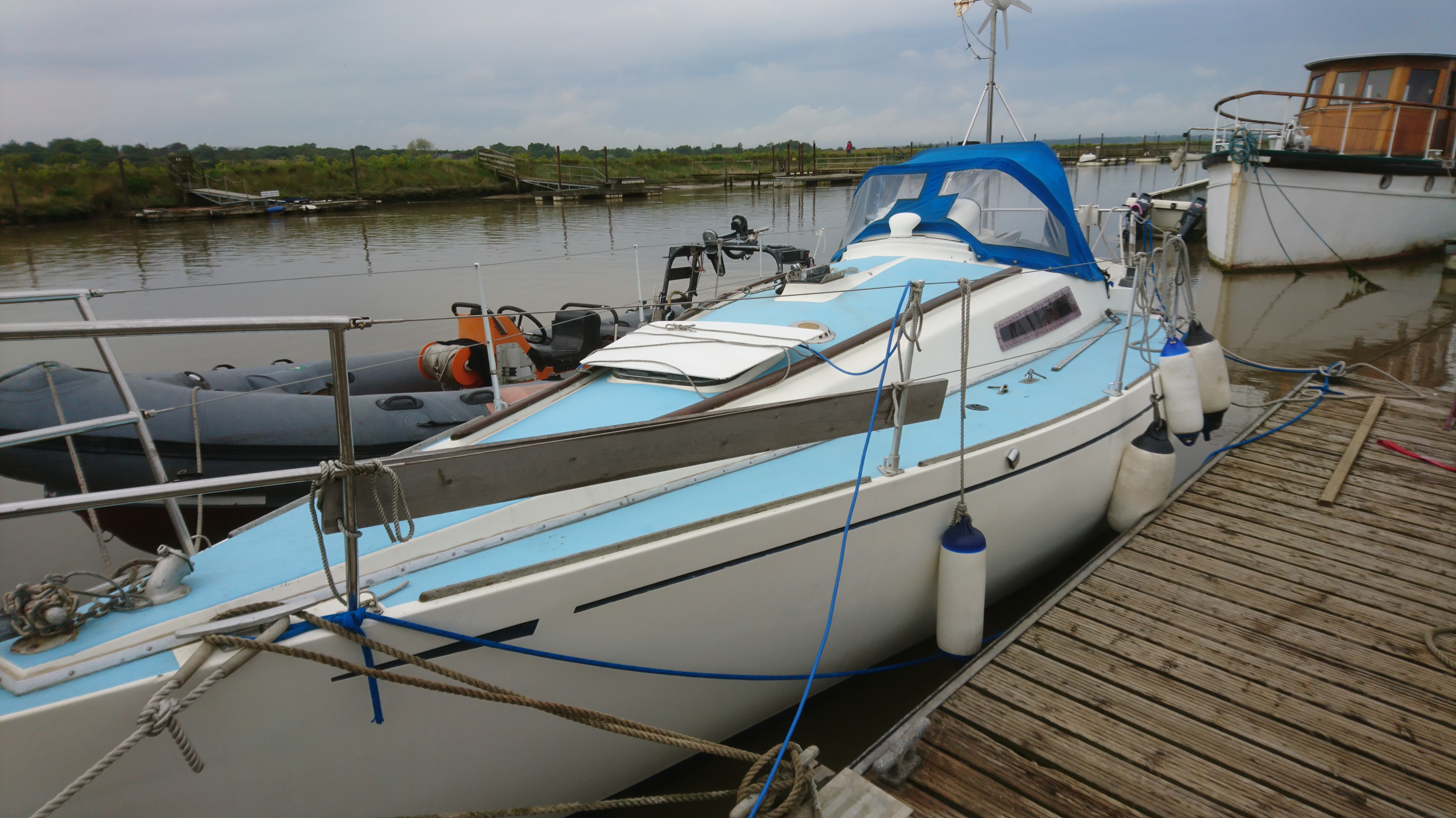
The Seamaster 925 that arrived at the yard looked very pretty with classic late 70’s lines and in allround very good condition.
However whoever designed and fitted the compression post was not having a good day or just wasn’t overly concerned about what would happen a few decades into the future.
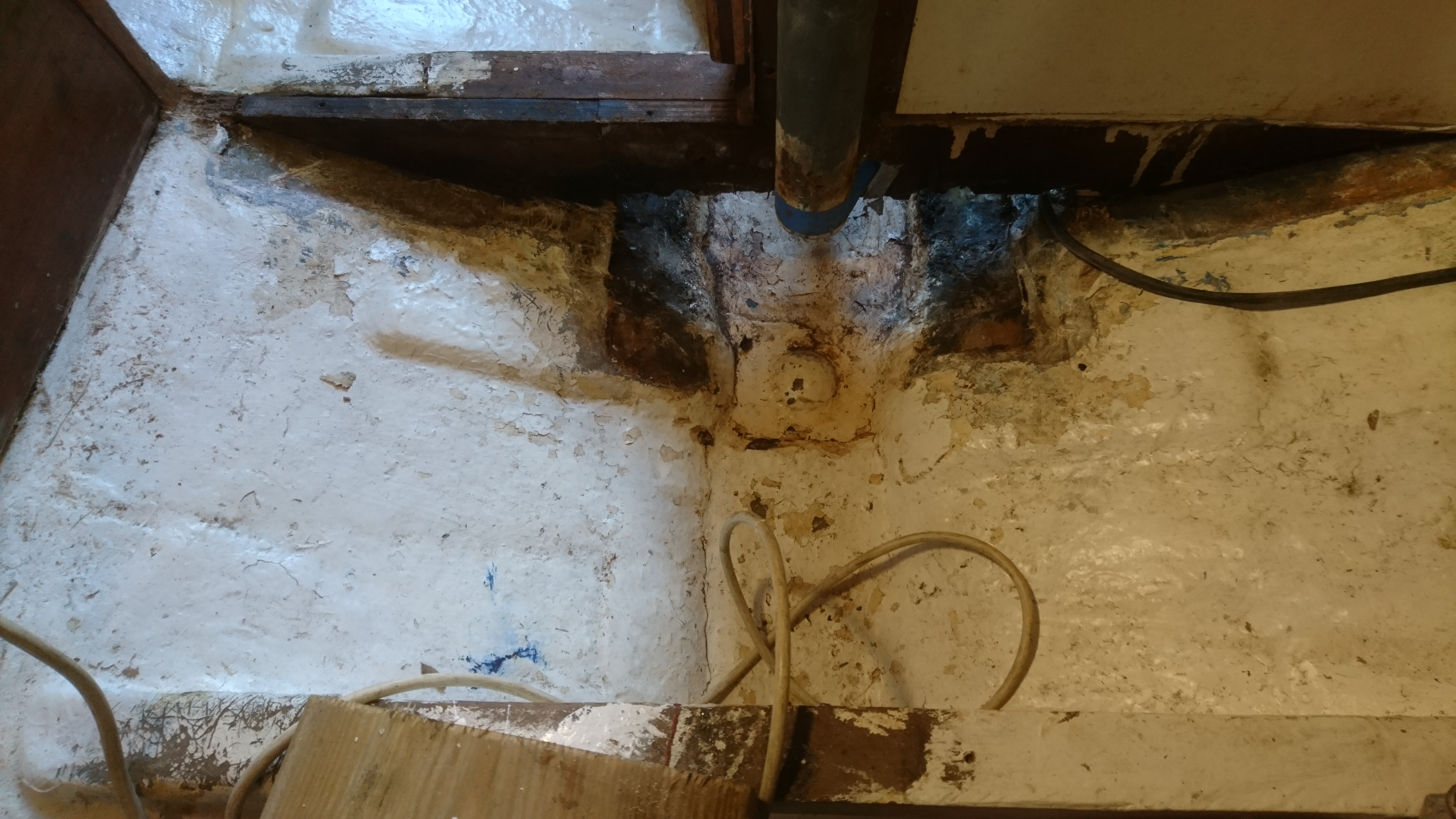
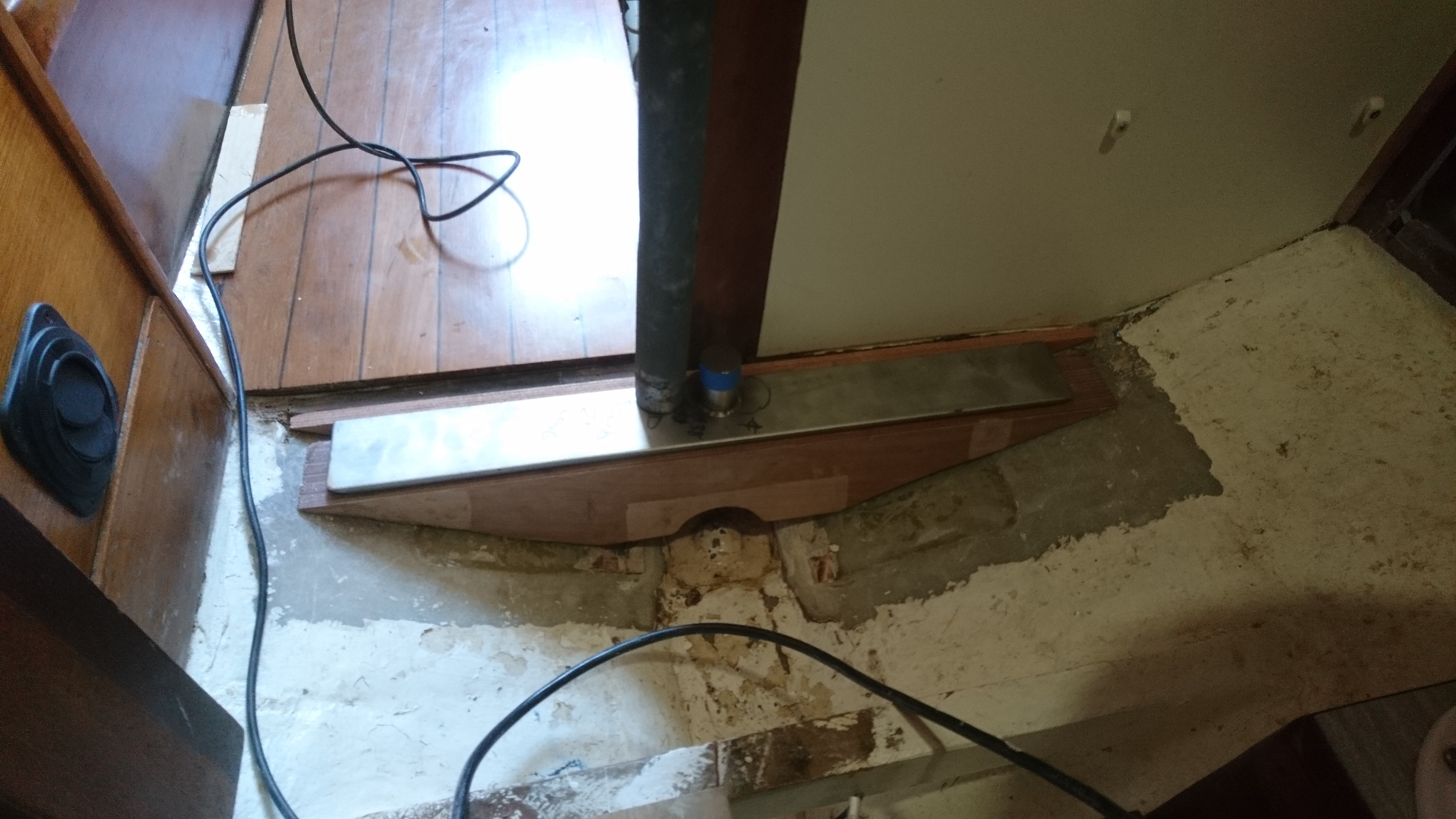
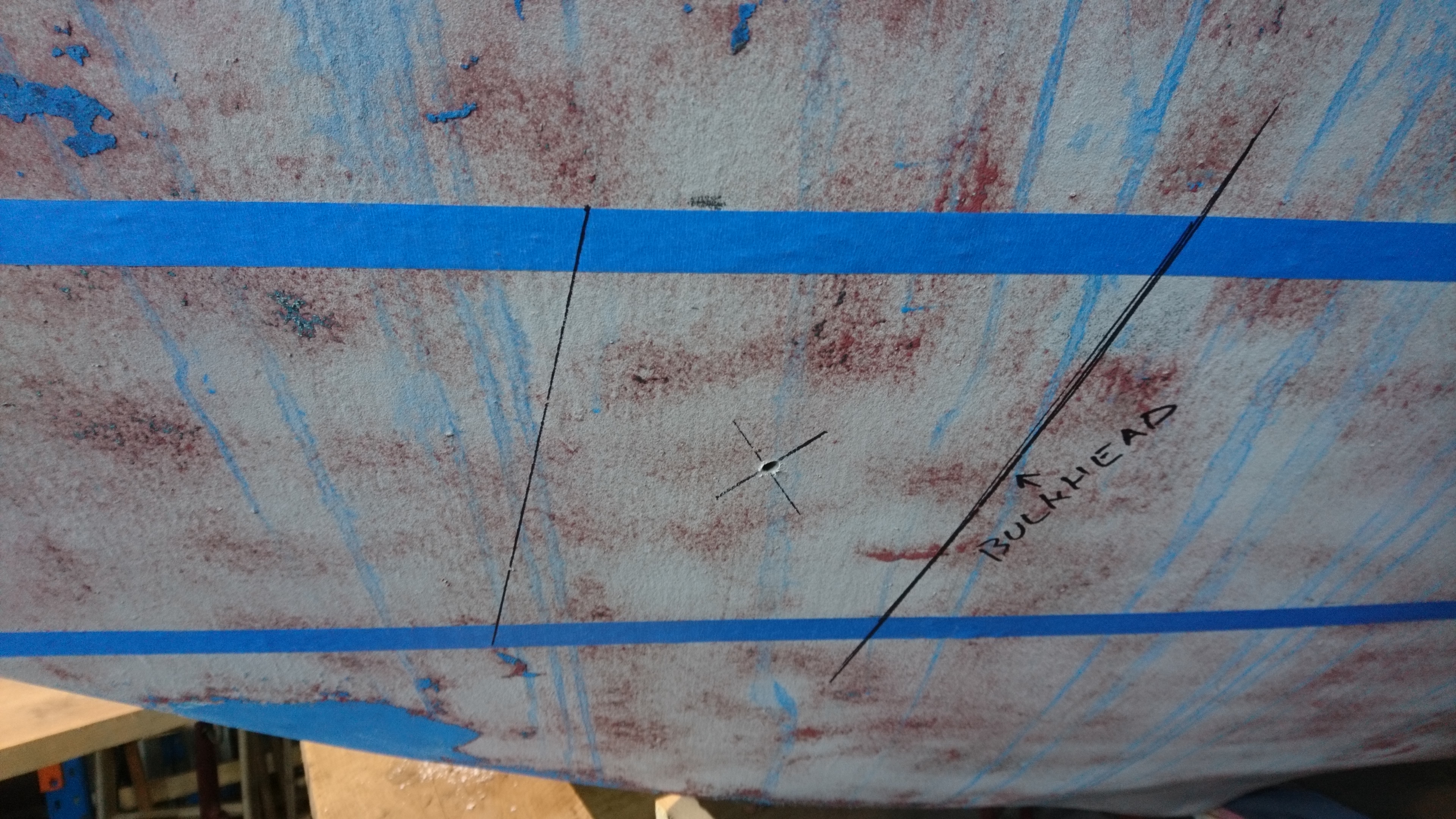
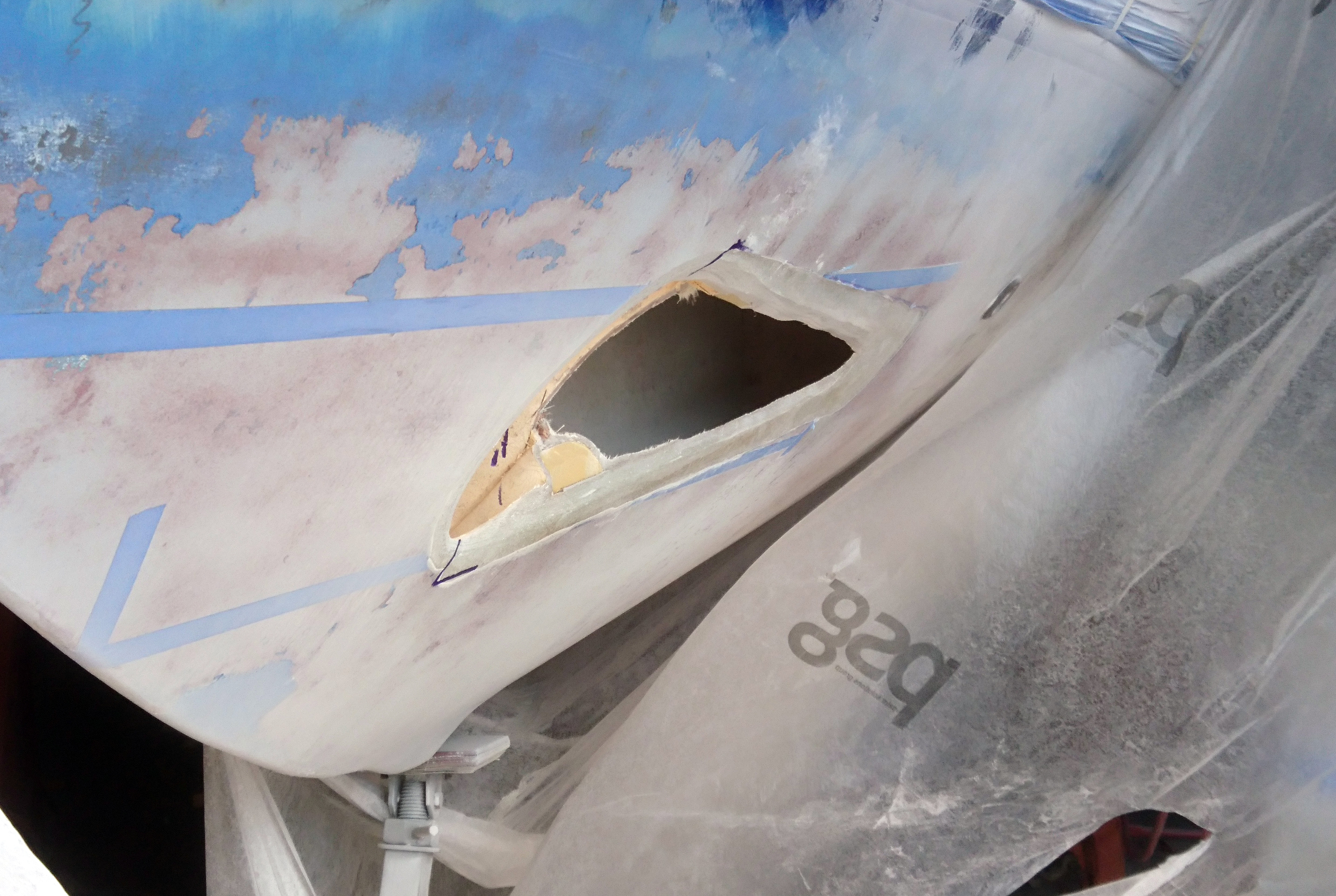
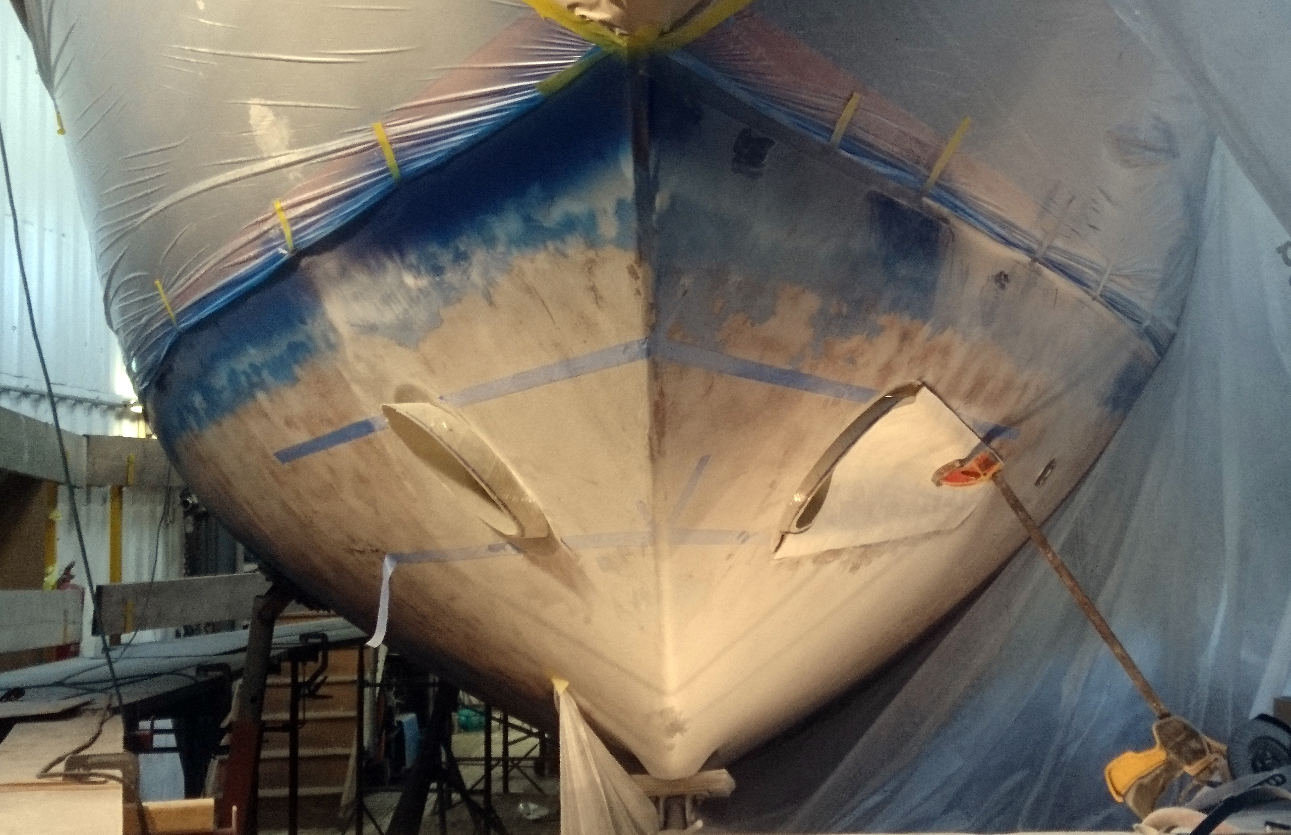
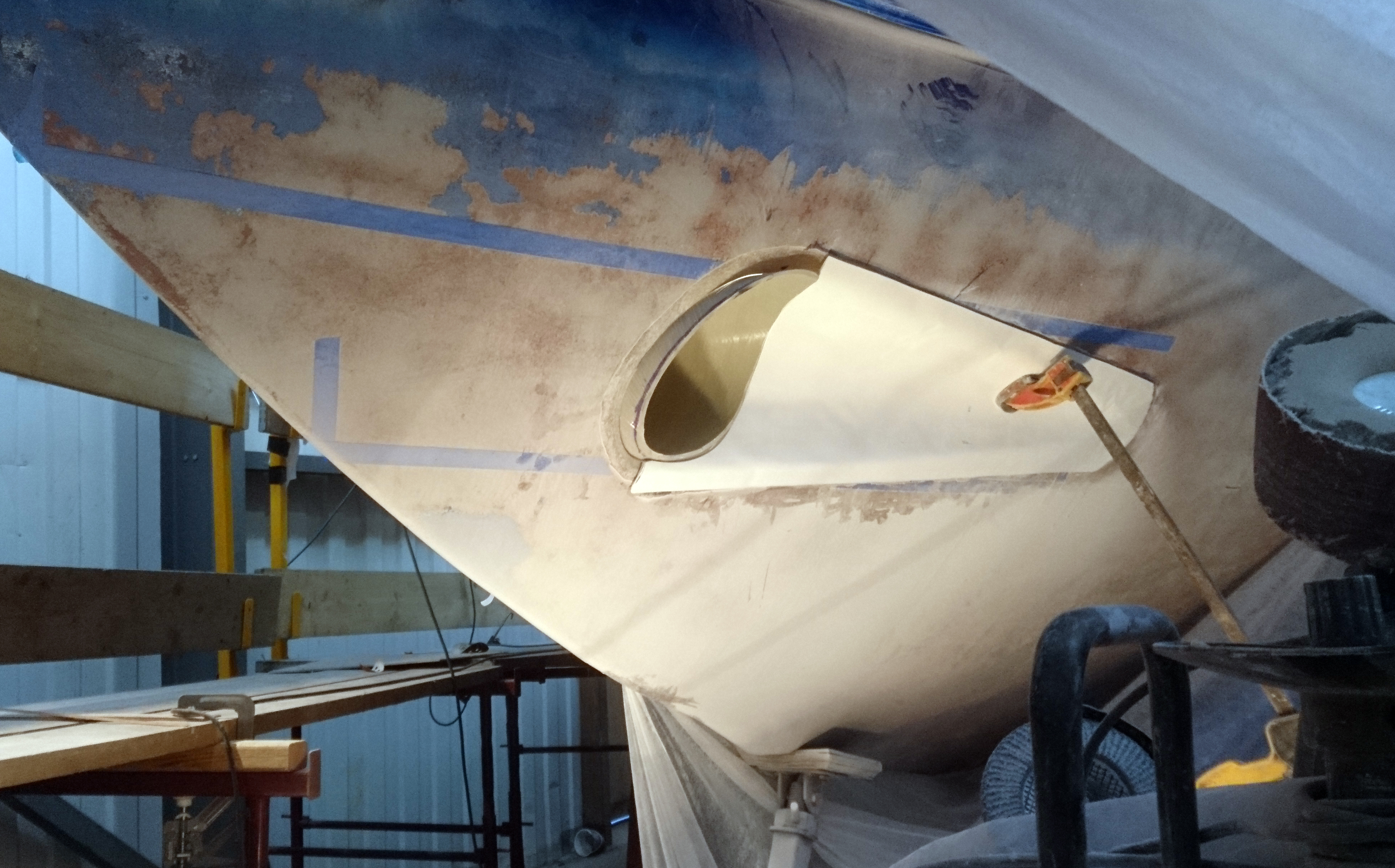
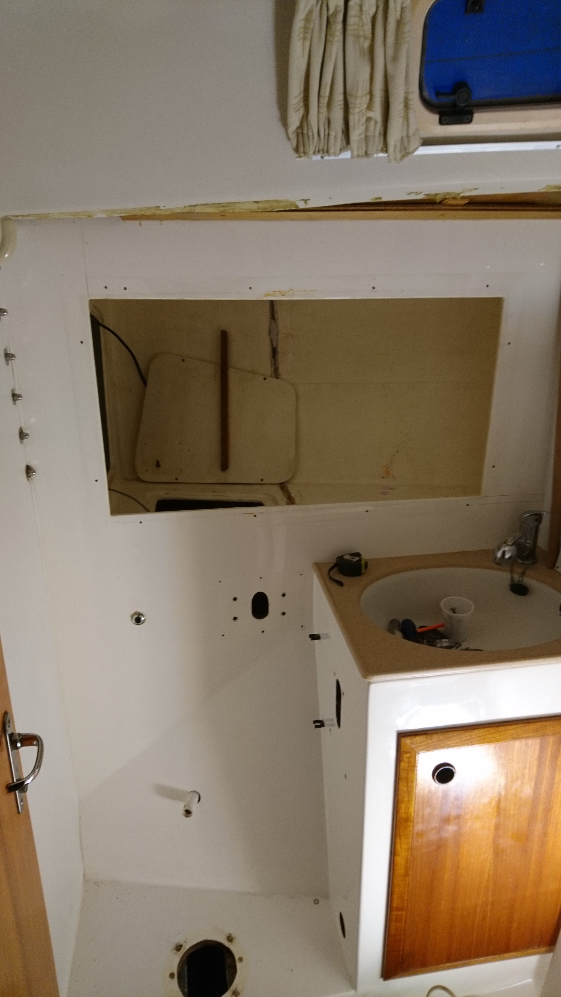
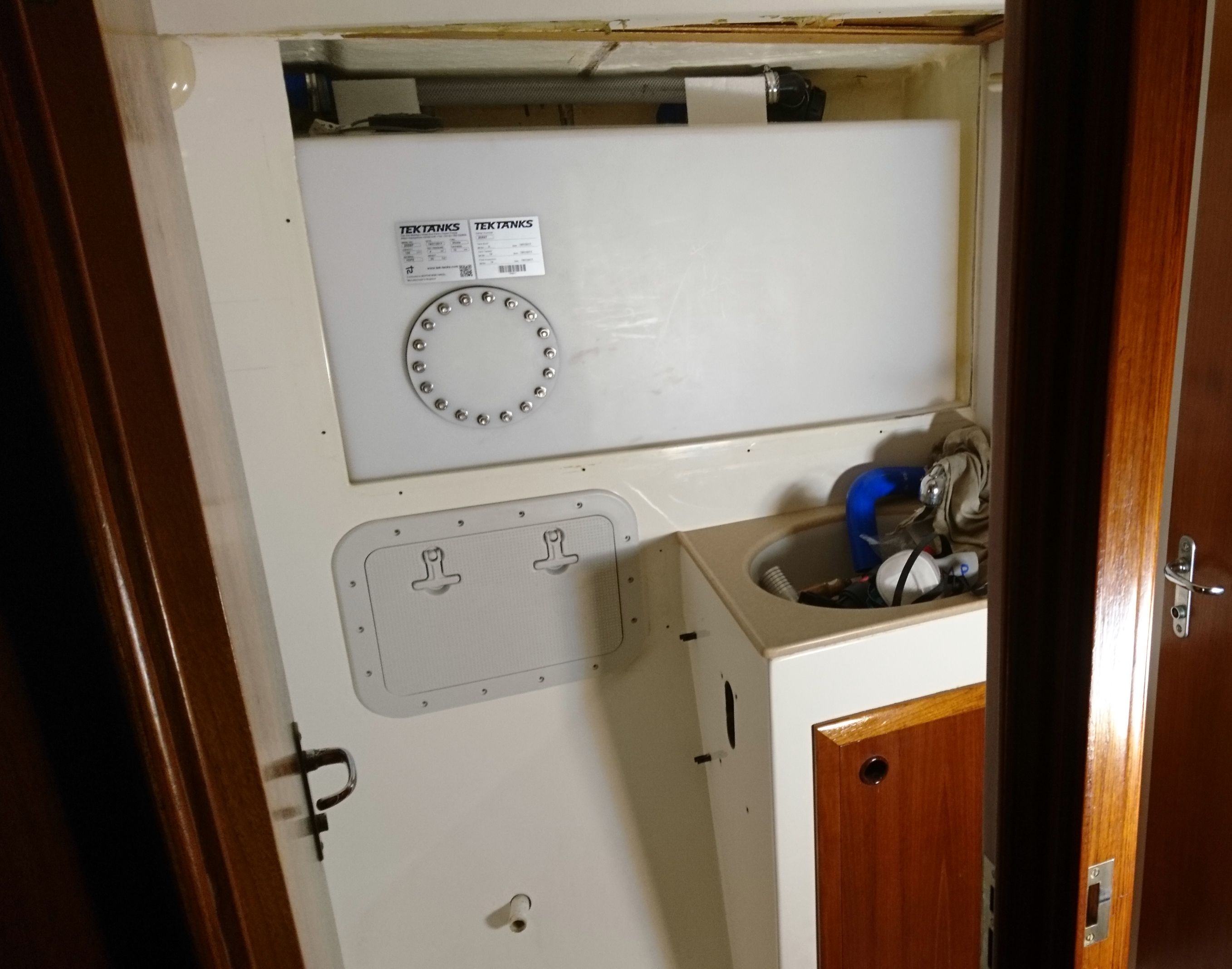
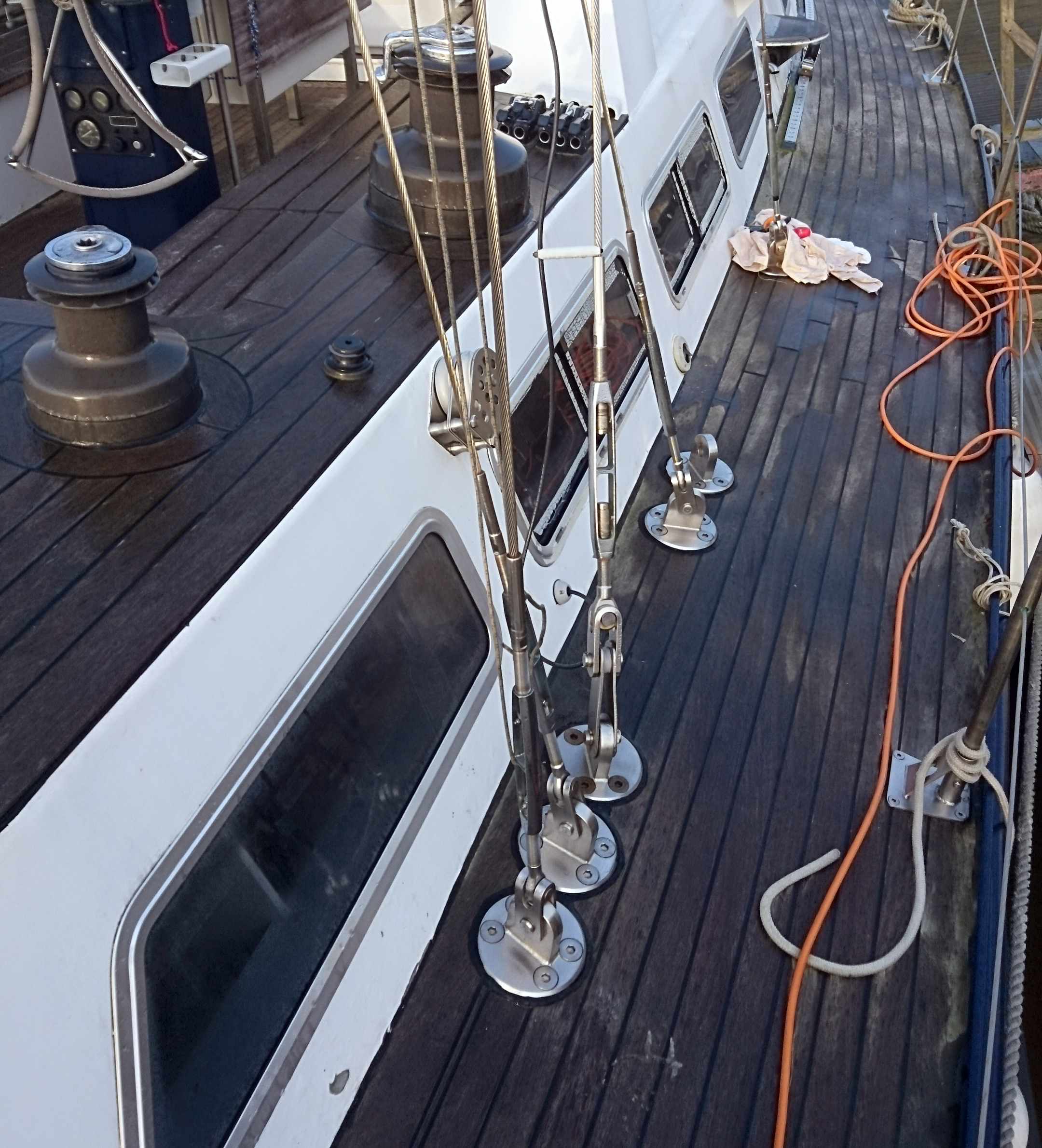
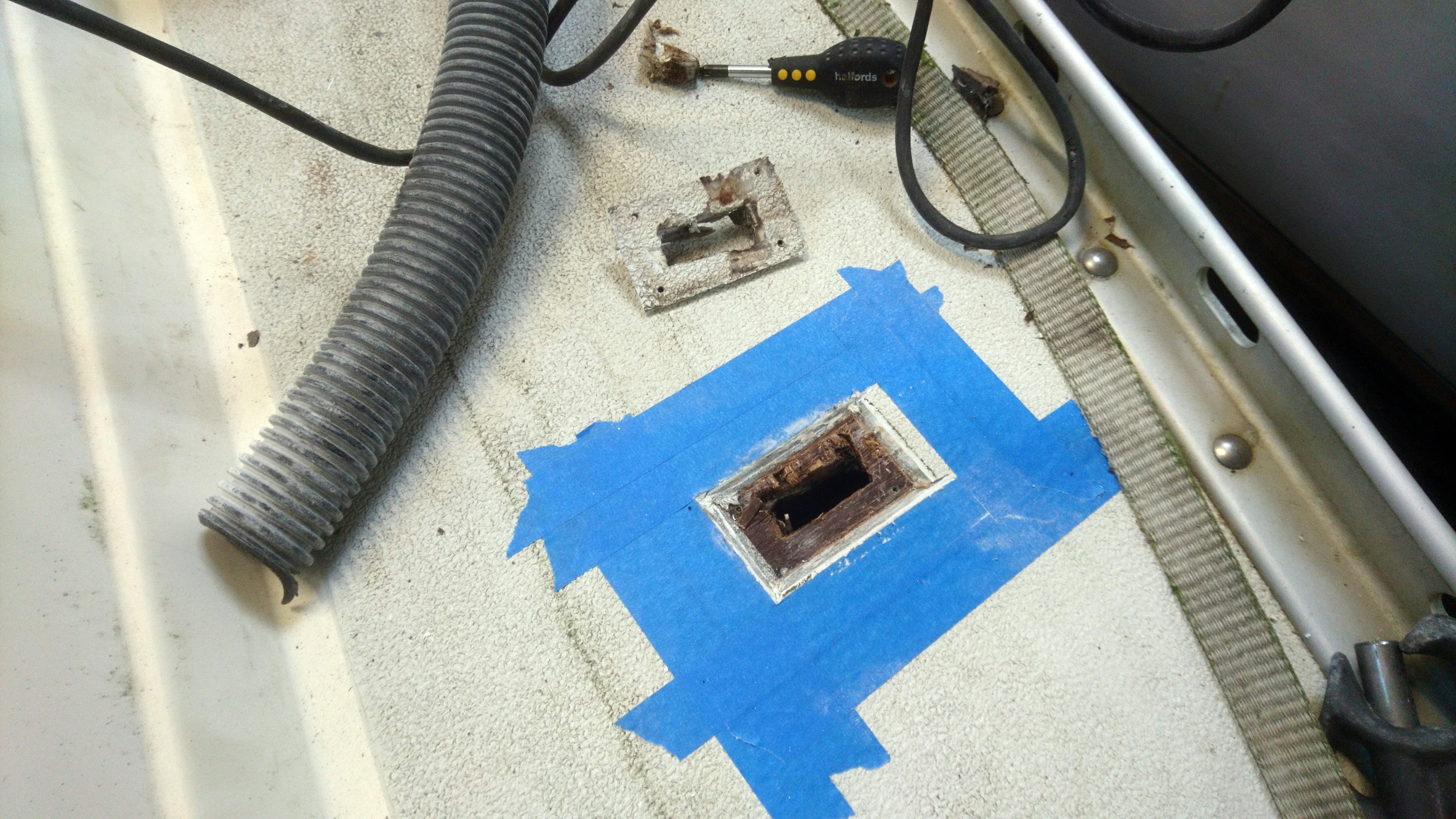
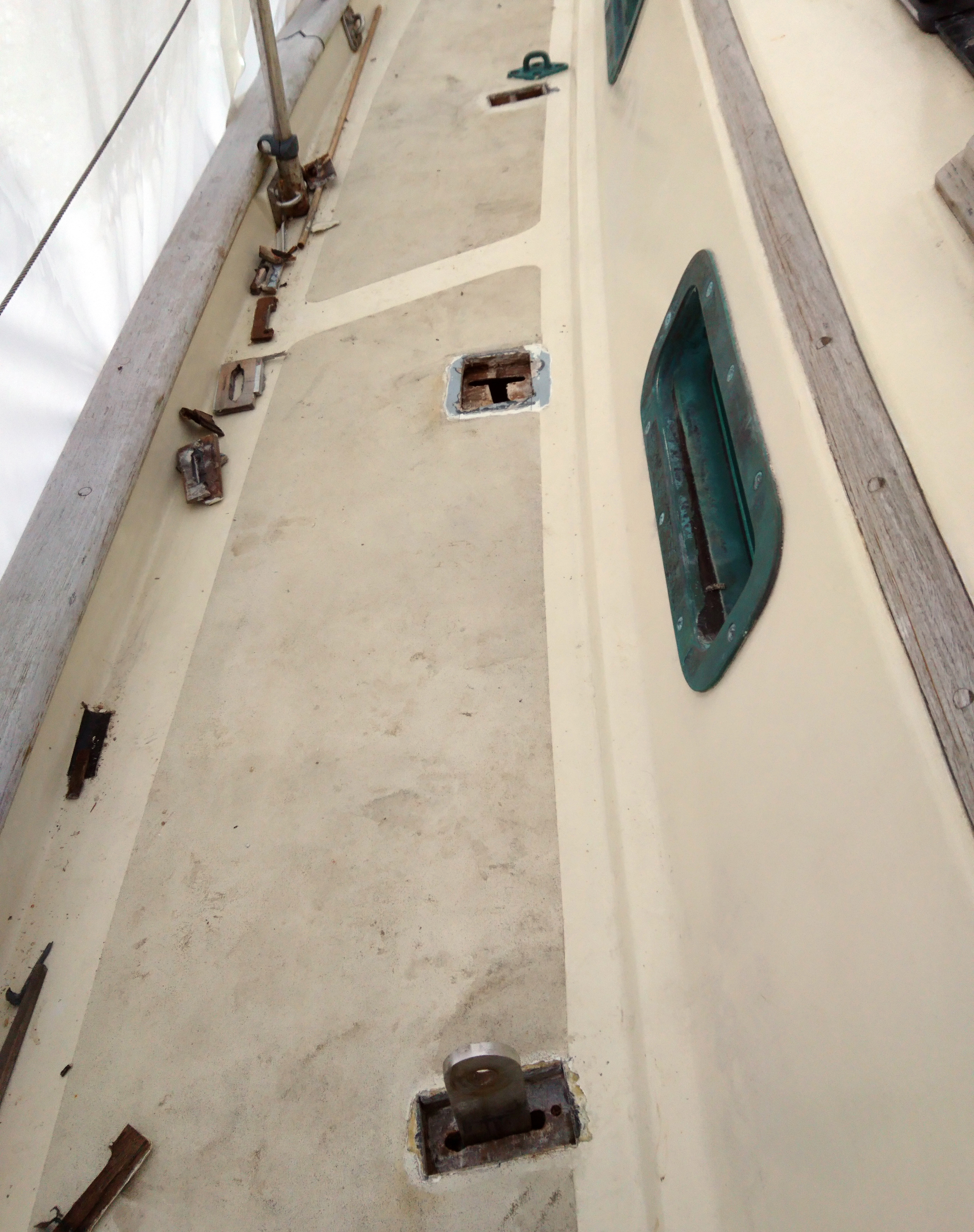
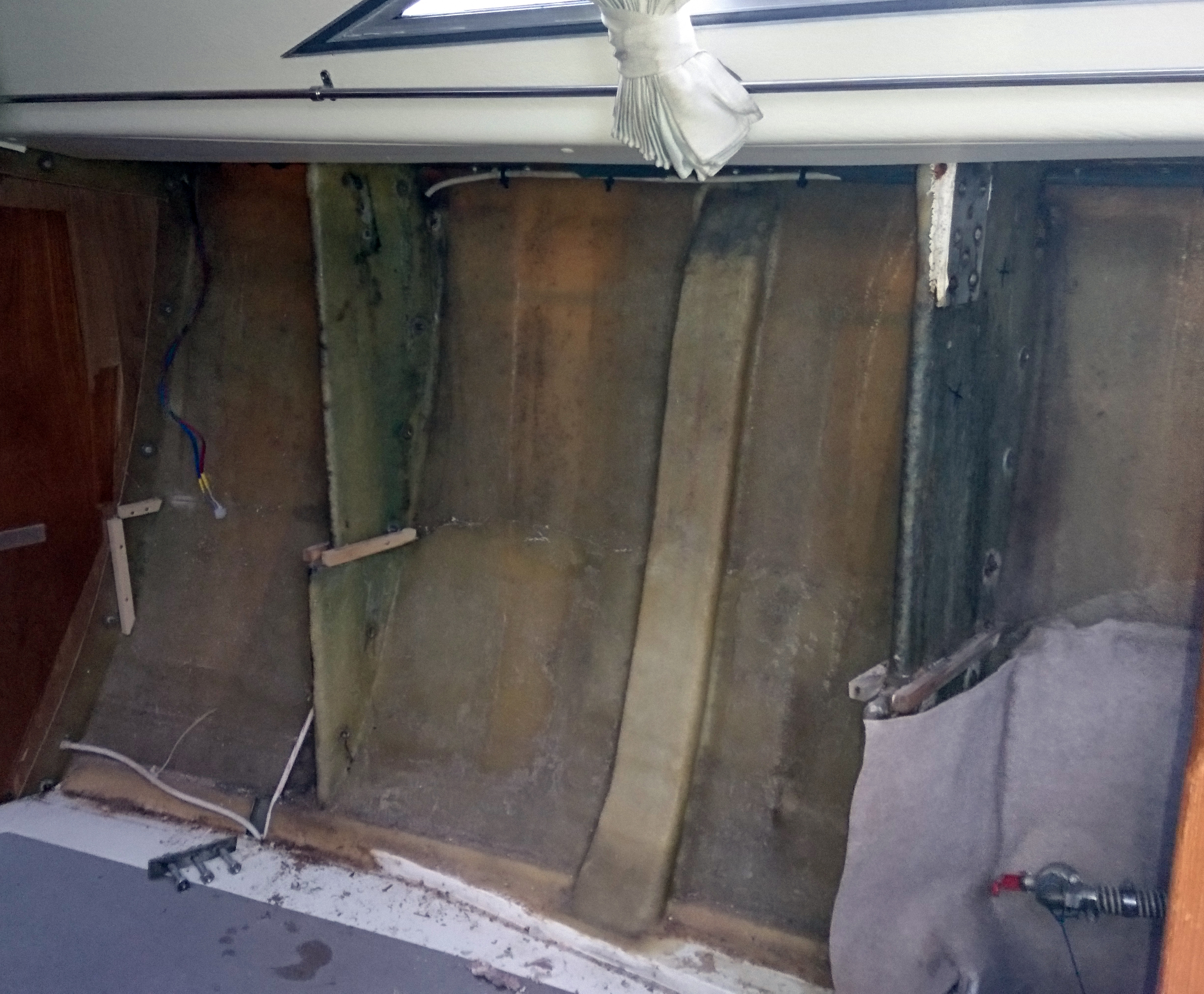
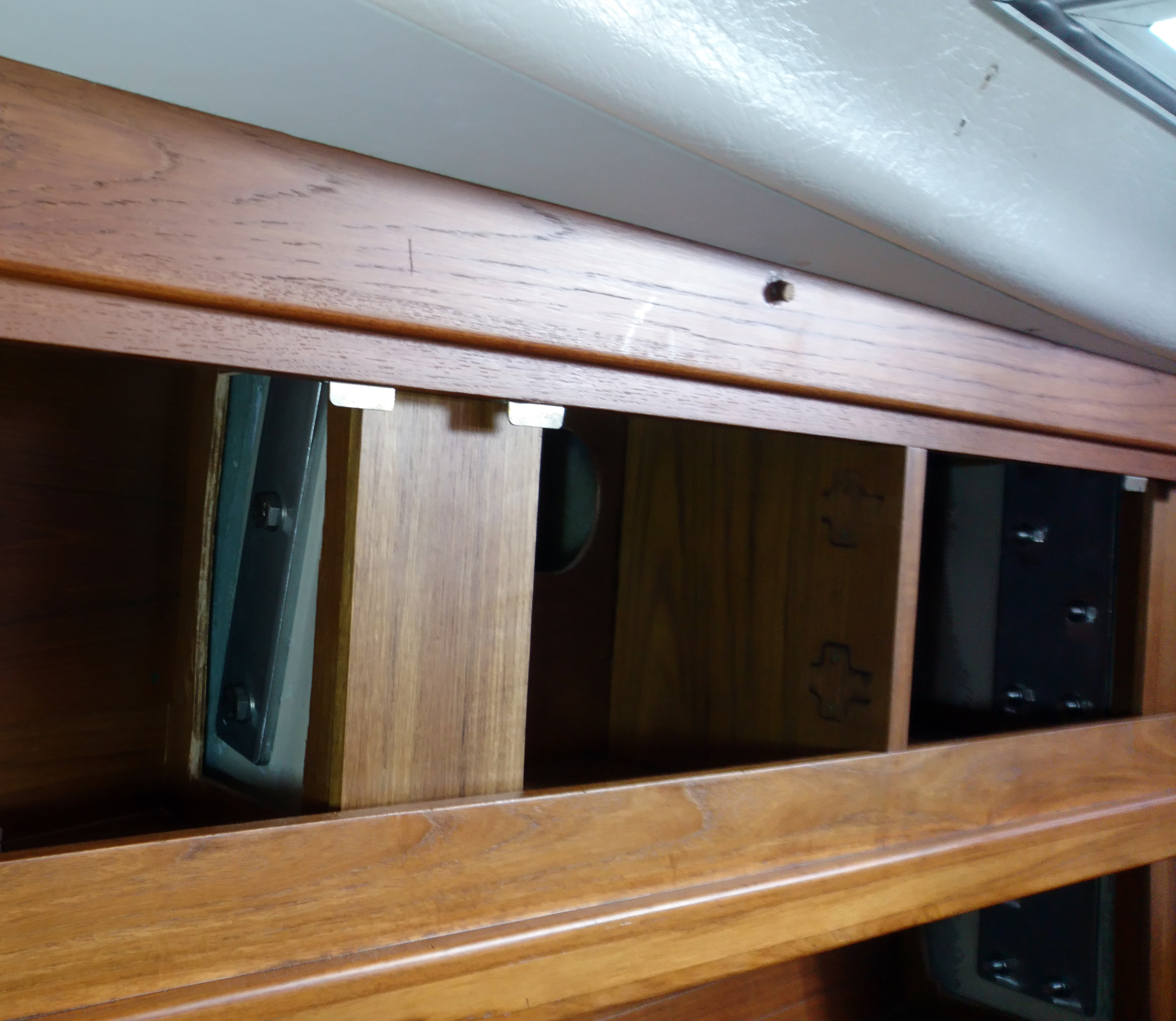
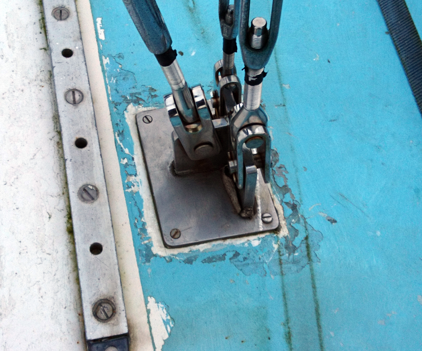
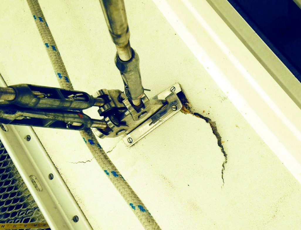
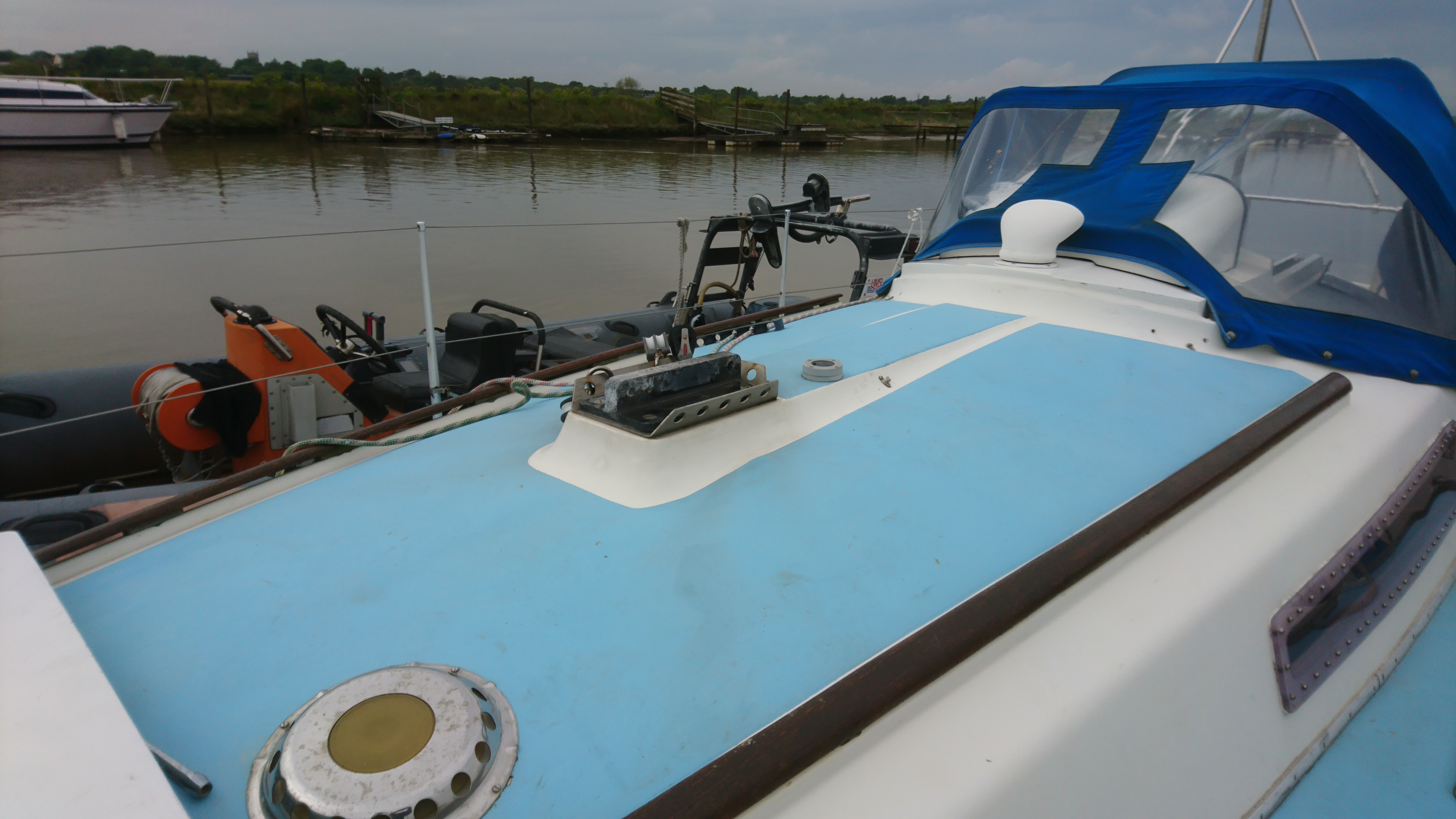
It was obvious something was wrong from outside, as there was a pronounced bump in the deck, next to the mast foot.
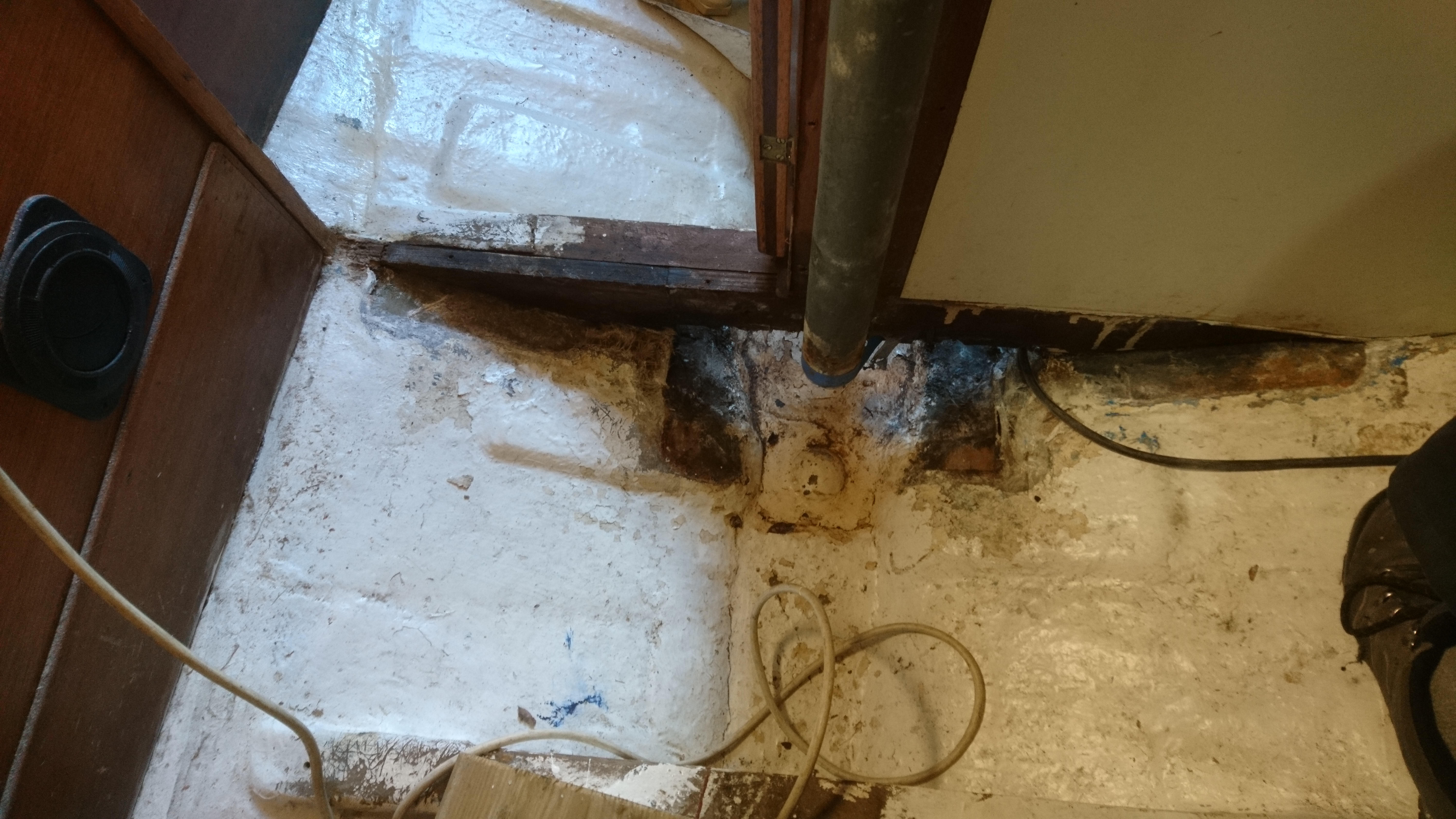
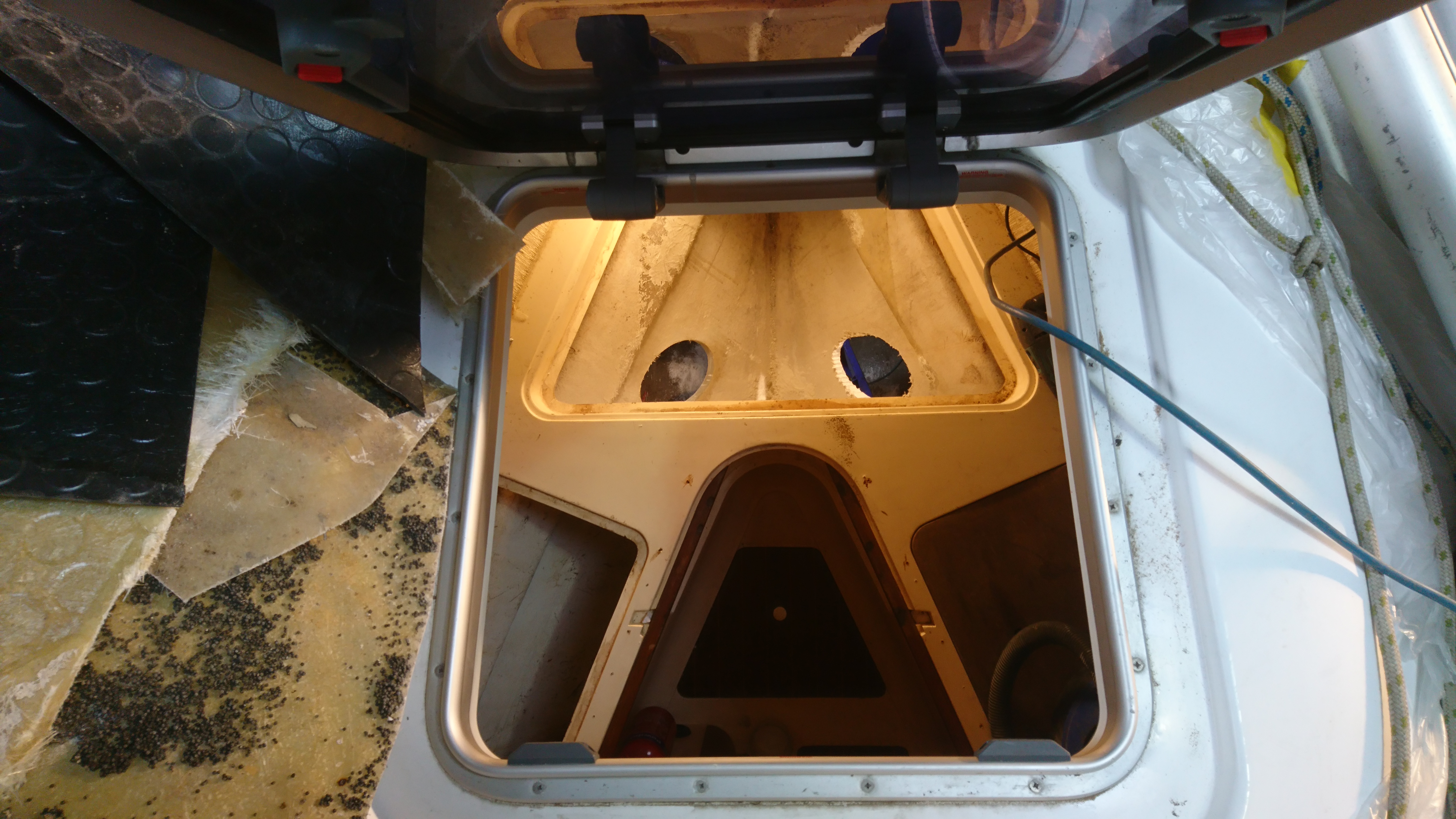
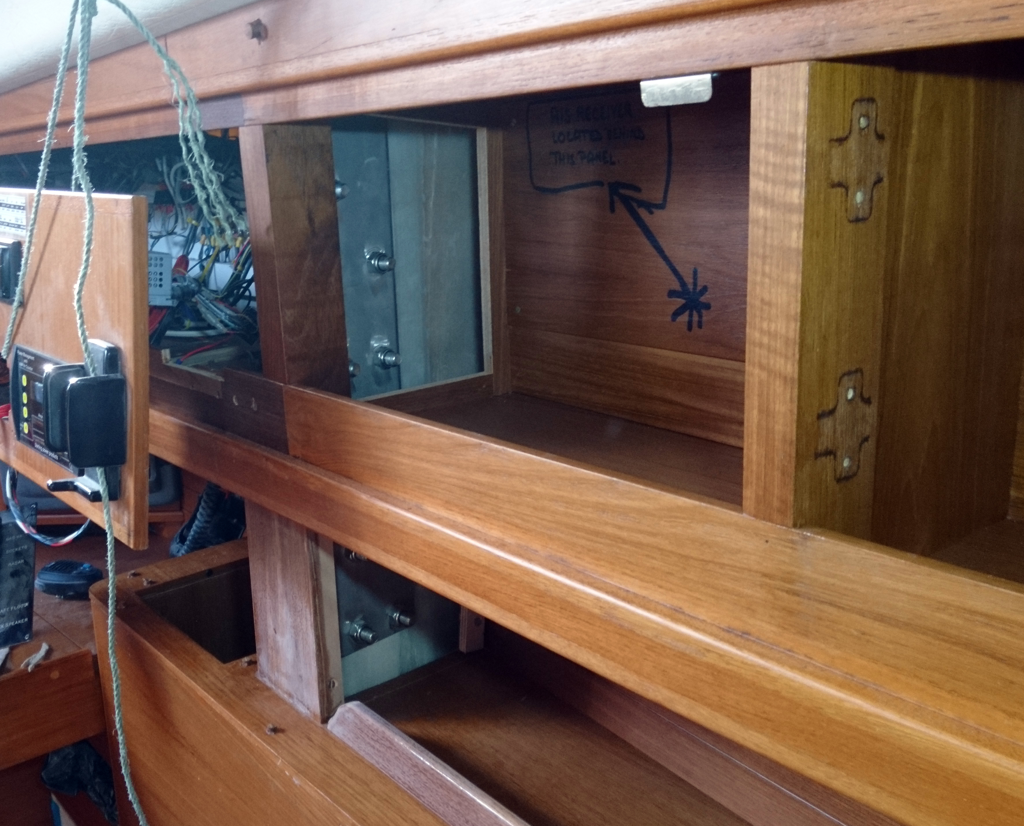
Investigating down below it became obvious what had happened.
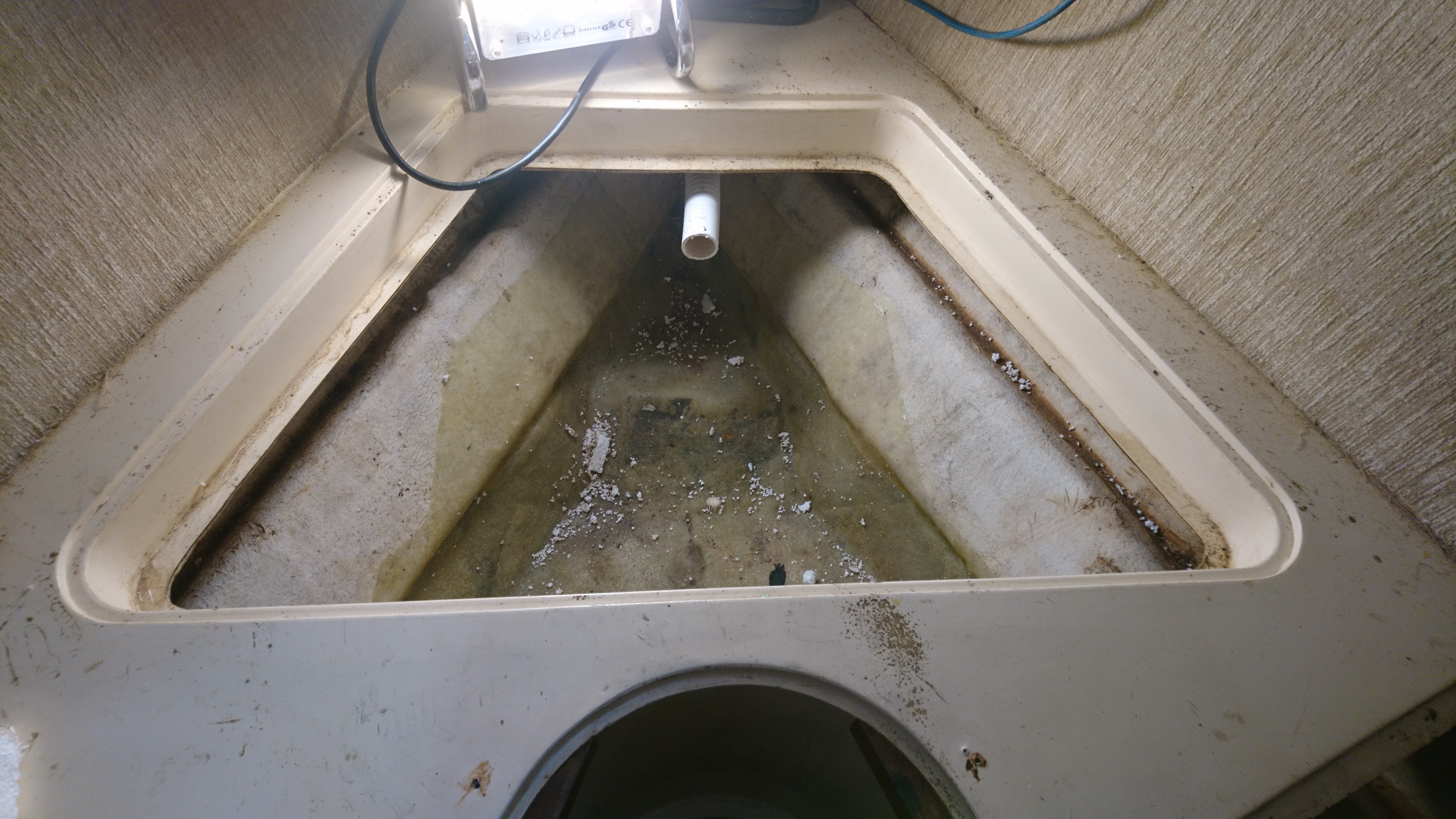
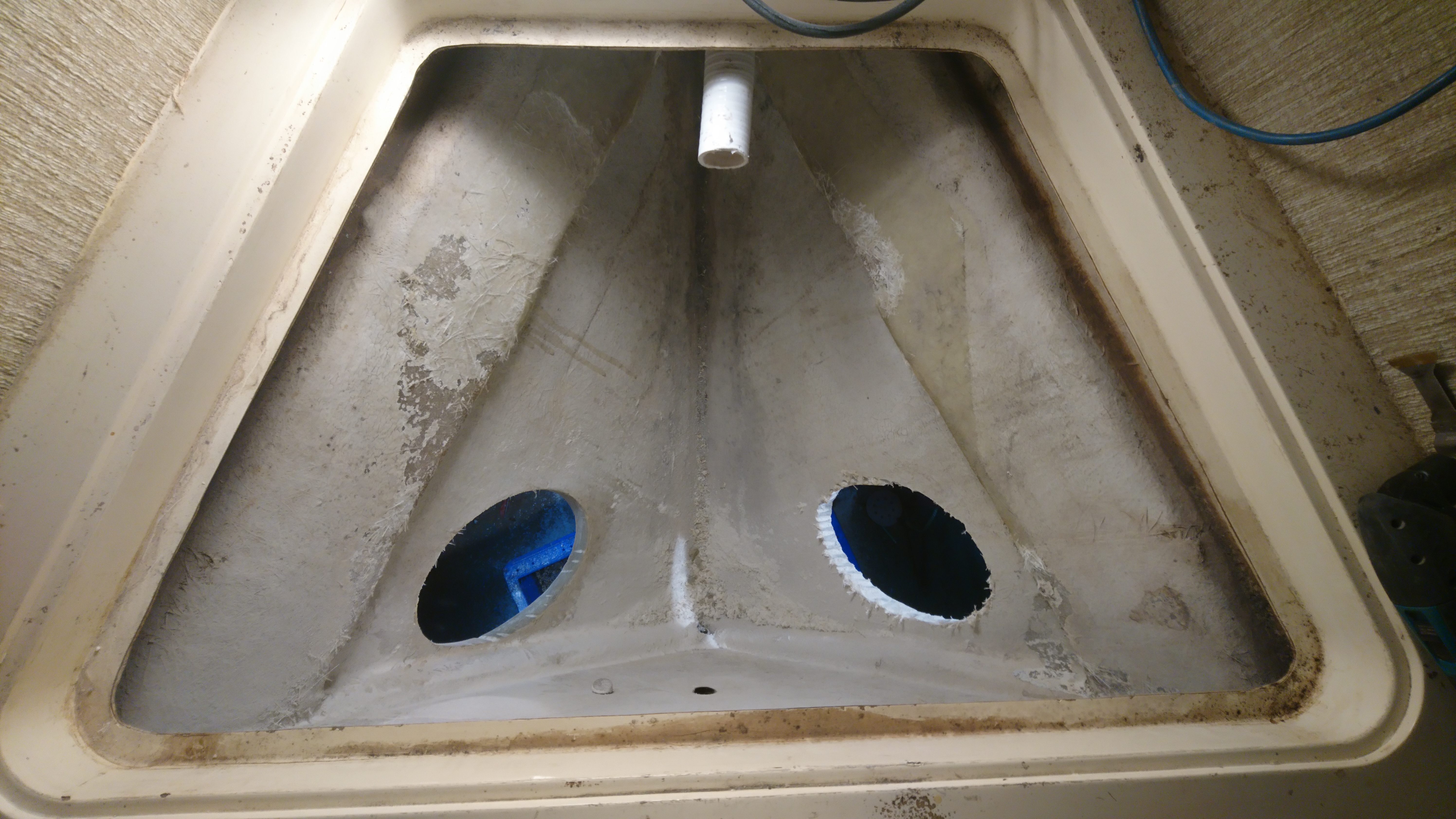
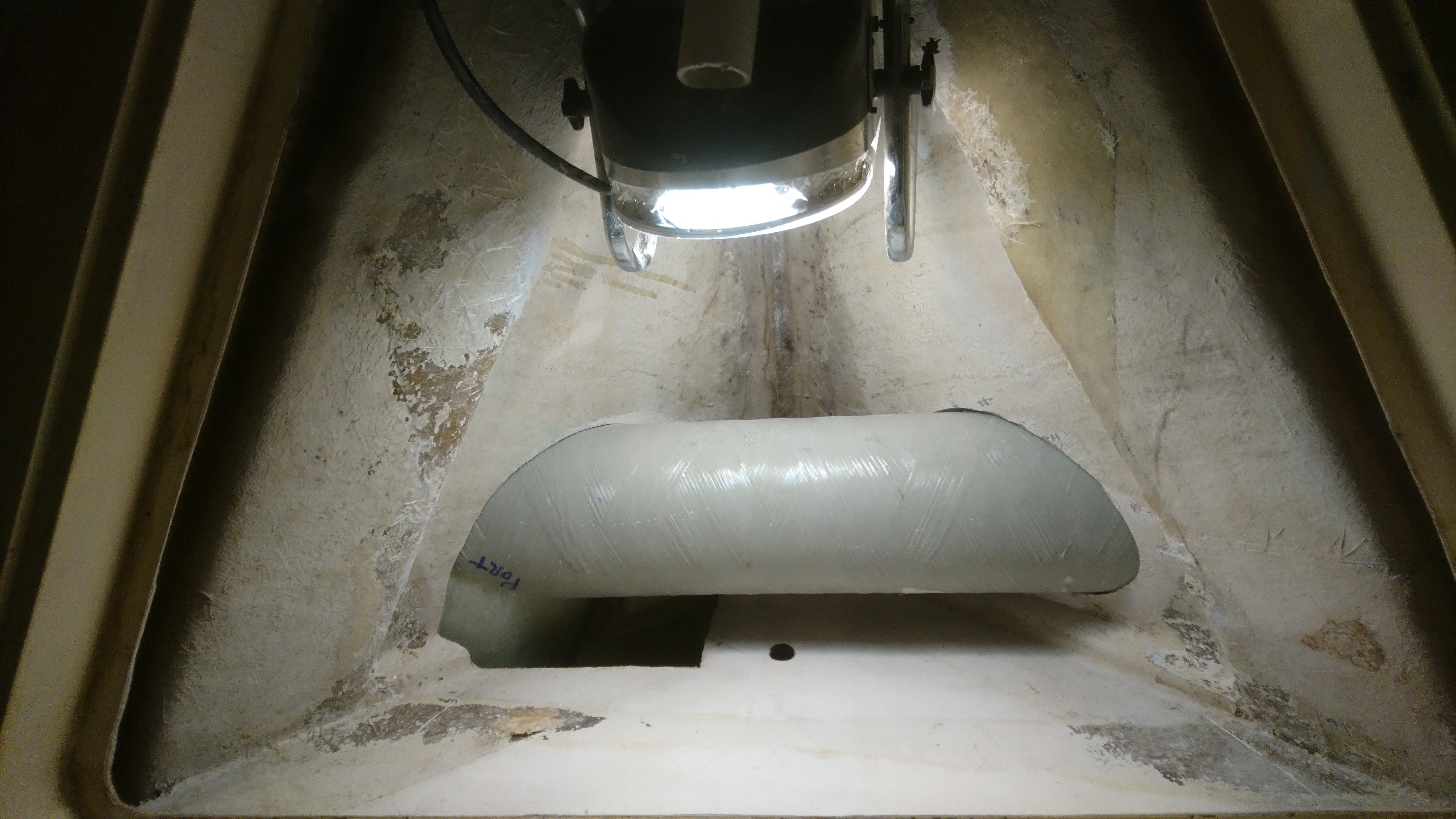
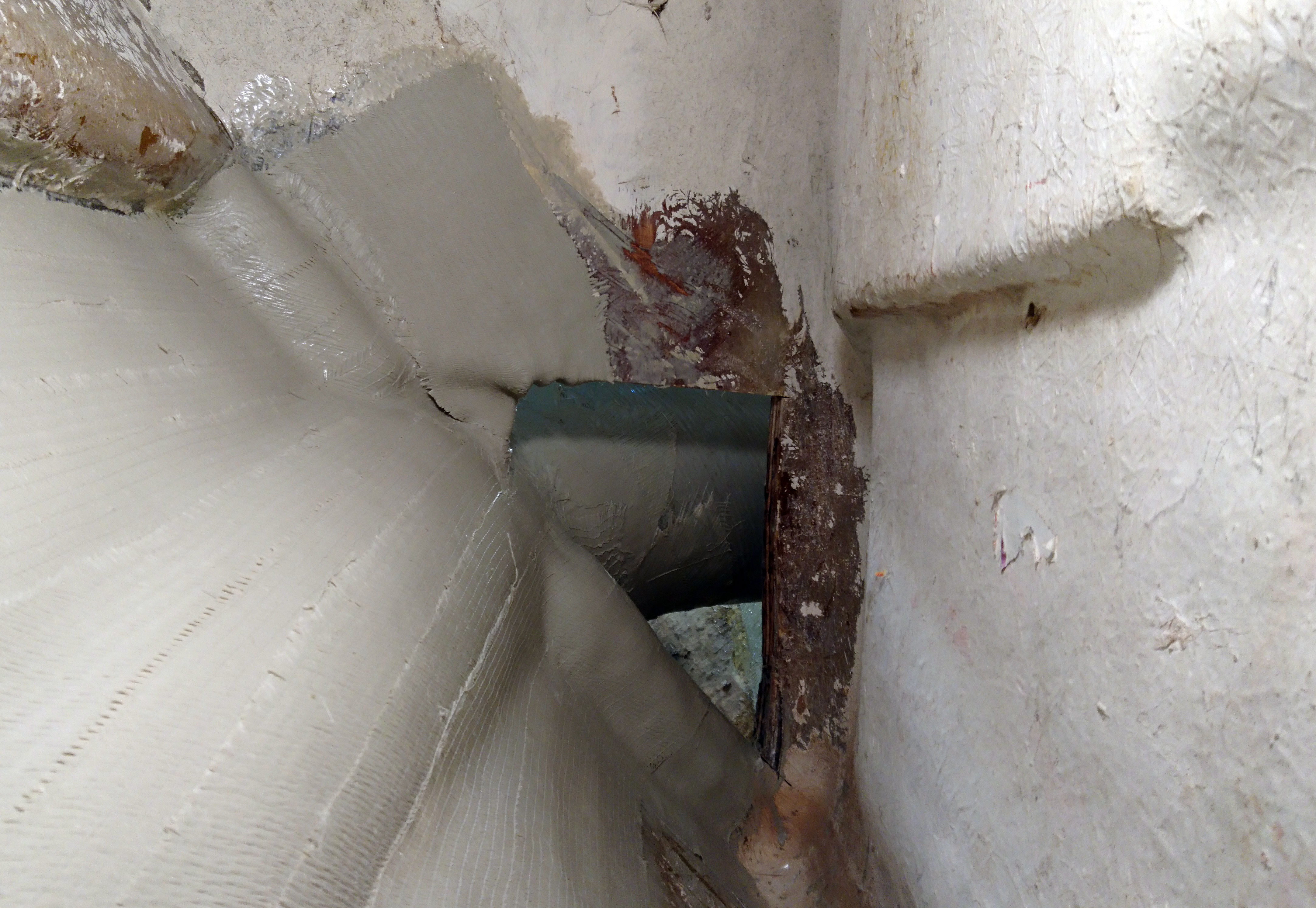
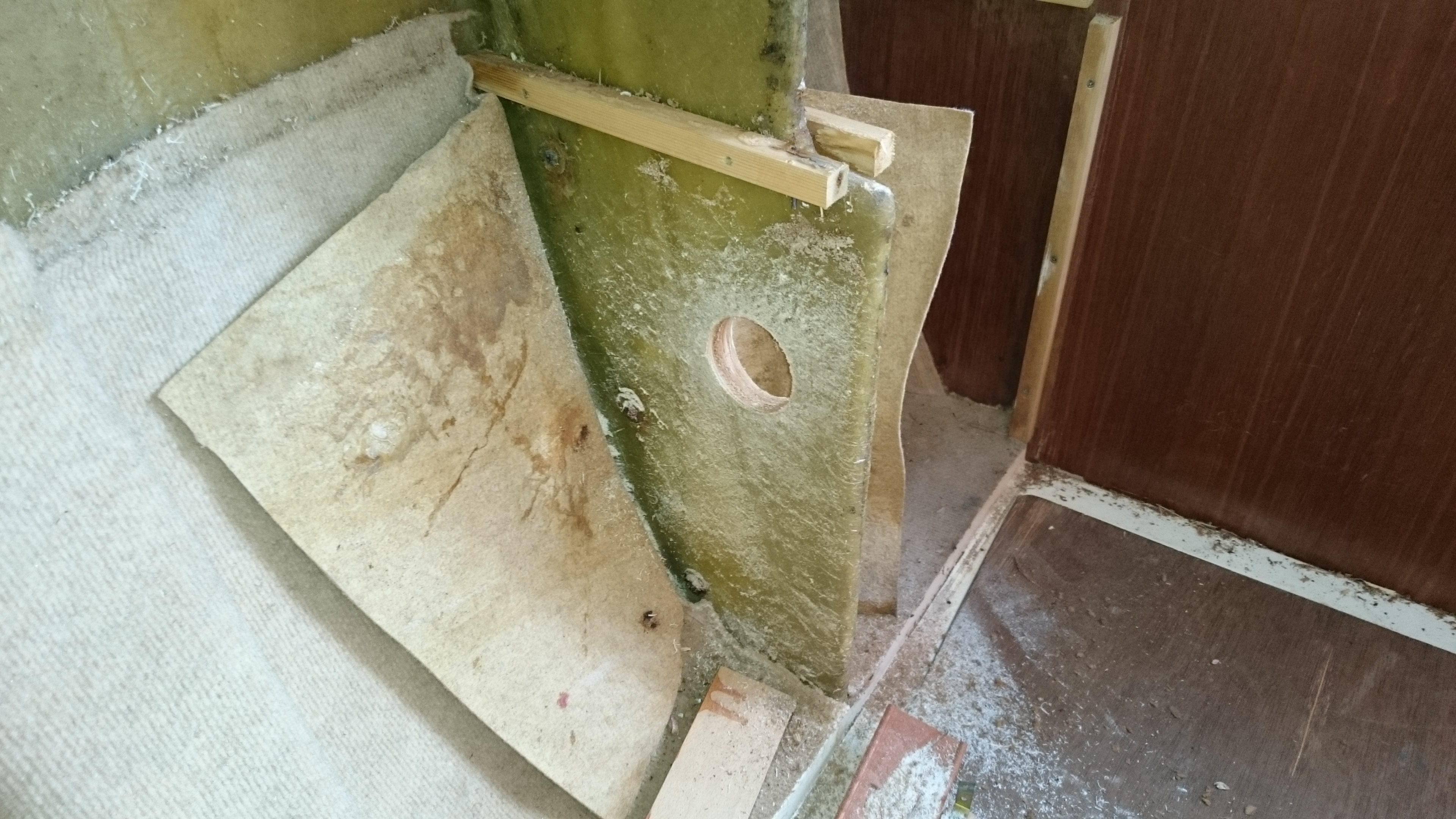
For some inexplicable reason the builder had positioned a keel bolt almost directly under the mast compression post.
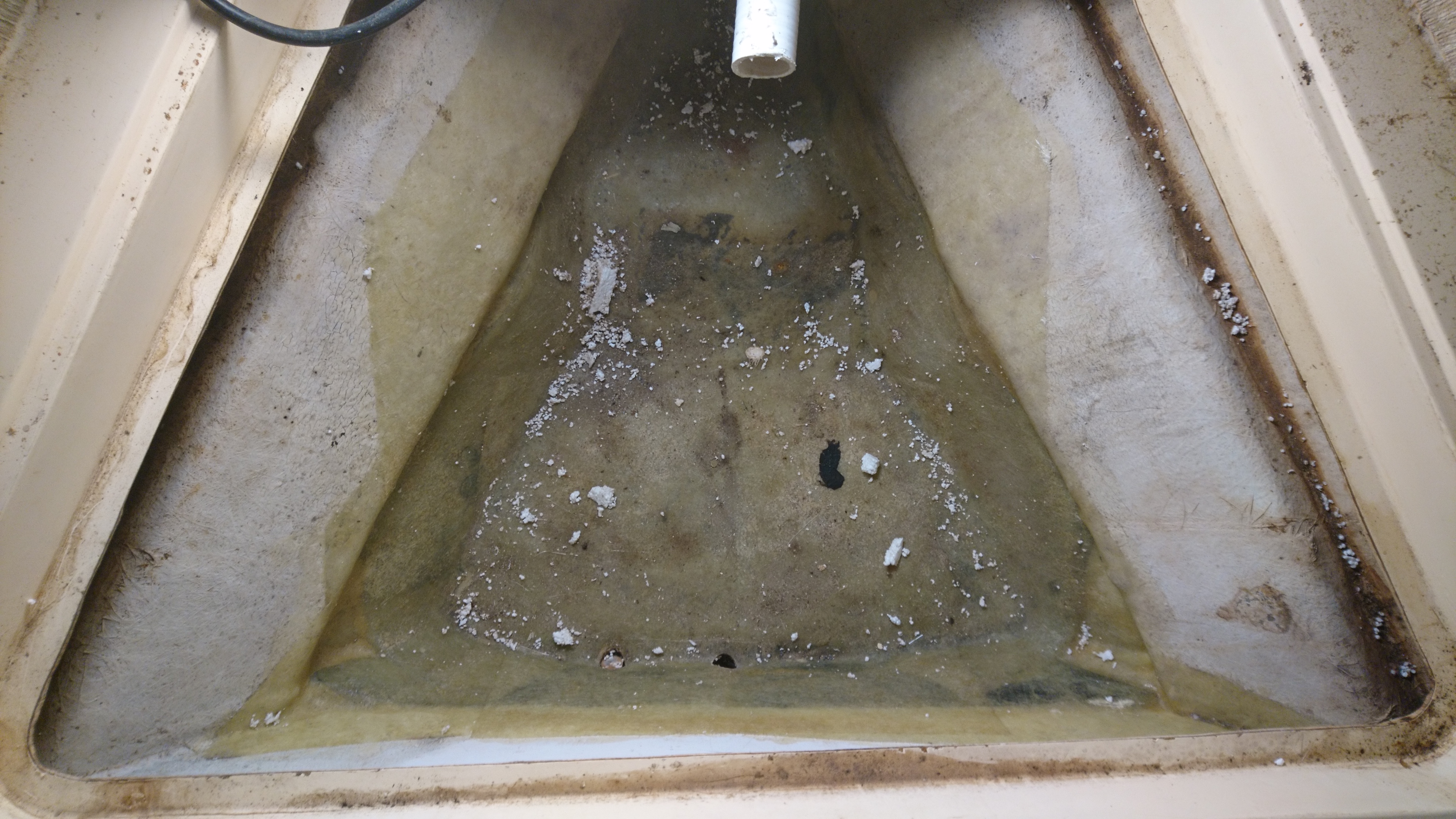
To enable access to this bolt they built a bridge across the bilge using 6mm steel plate.
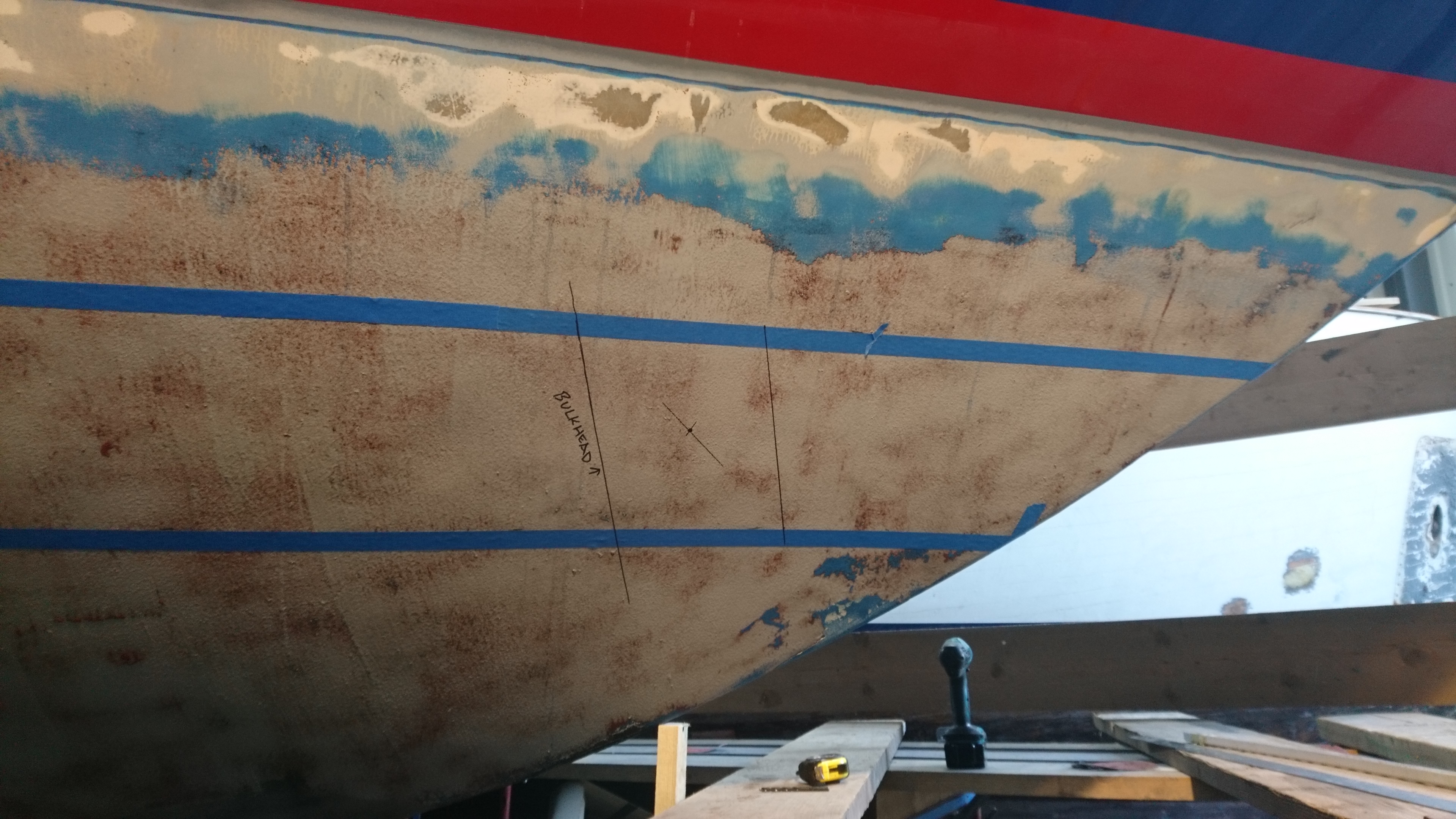
Over time the plate corroded and the bridge collapsed due to the rig loads and the deck was pressed down onto the saloon bulkhead, just aft of the post.
Over a little more time the inner skin of the deck gave way crushing the balsa core and created an external bump in the glass outer skin.
Obviously if this continued the deck would have been pierced with the real possibility of losing the rig over the side.

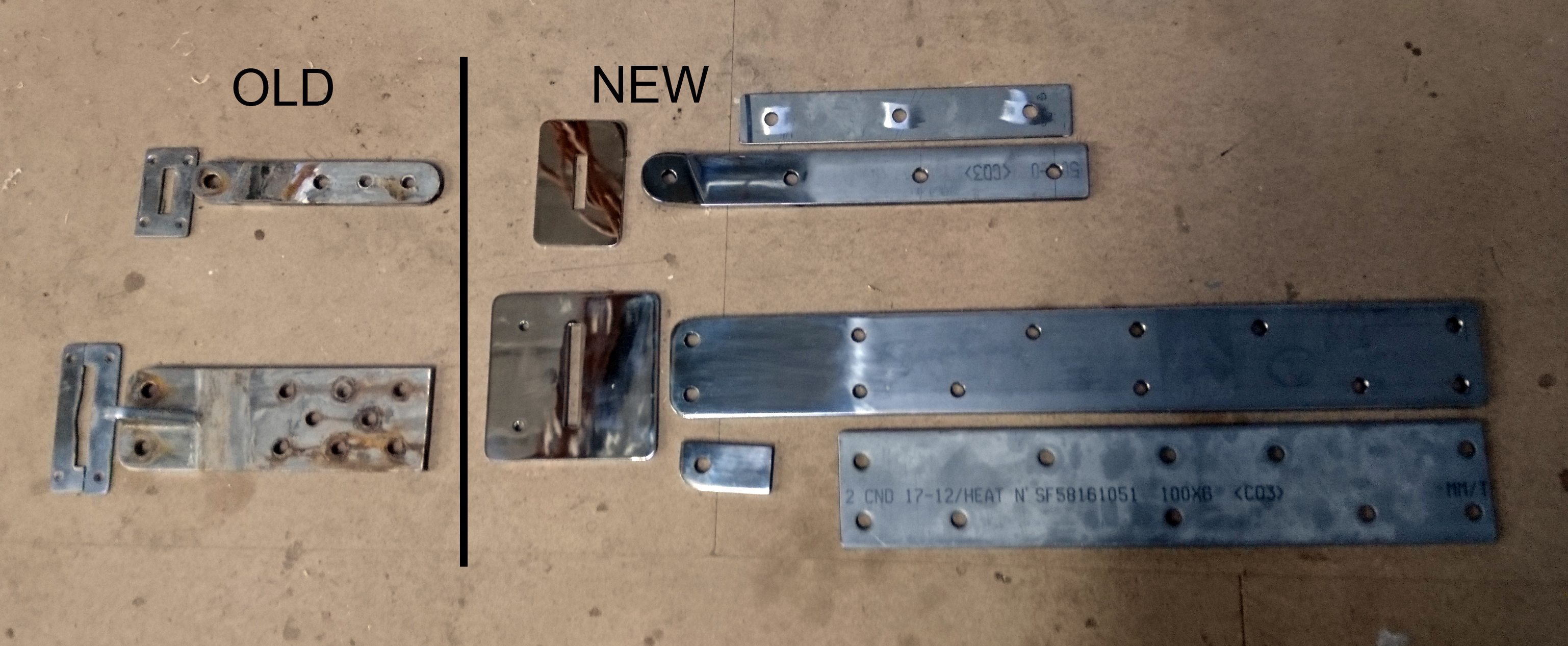
The answer was simple, make a bigger, stronger, more supportive base for the compression post.
Initially I wanted to try and repair without dropping the rig to save the owner a few bob but even with all the rig tension slackened off there was still too much flex in the deck.
Lucky for us our mobile crane can unstep a mast without us having to haul the boat out and so an hour later the rig was sitting on trestles on the pontoon.
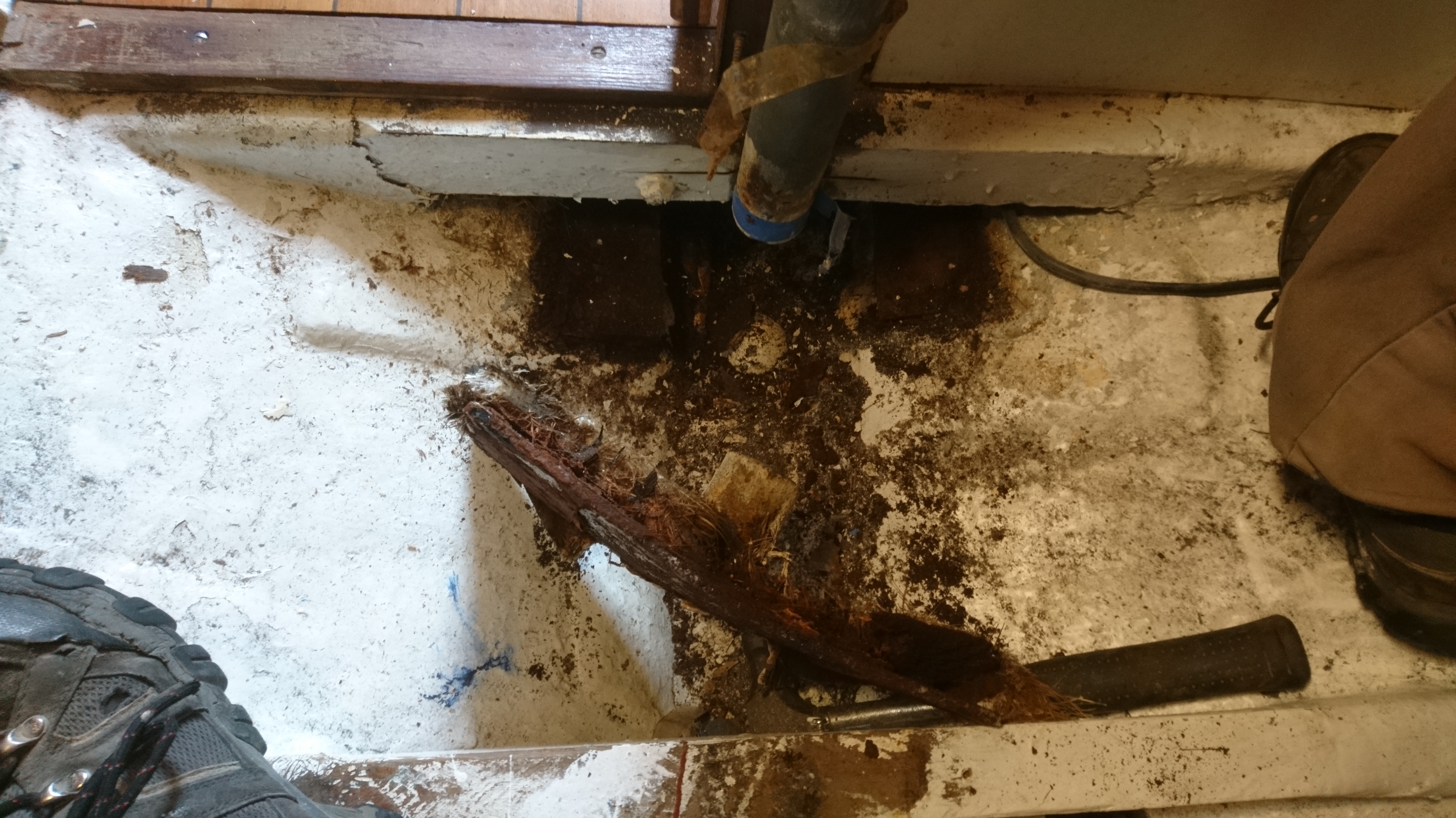
The task of getting the old post out, which appeared to have been fitted before the main saloon bulkhead was not quite so straight forward.
There simply was no way to get the post out in one piece and even then a section at the top of the bulkhead would have to be cut away.
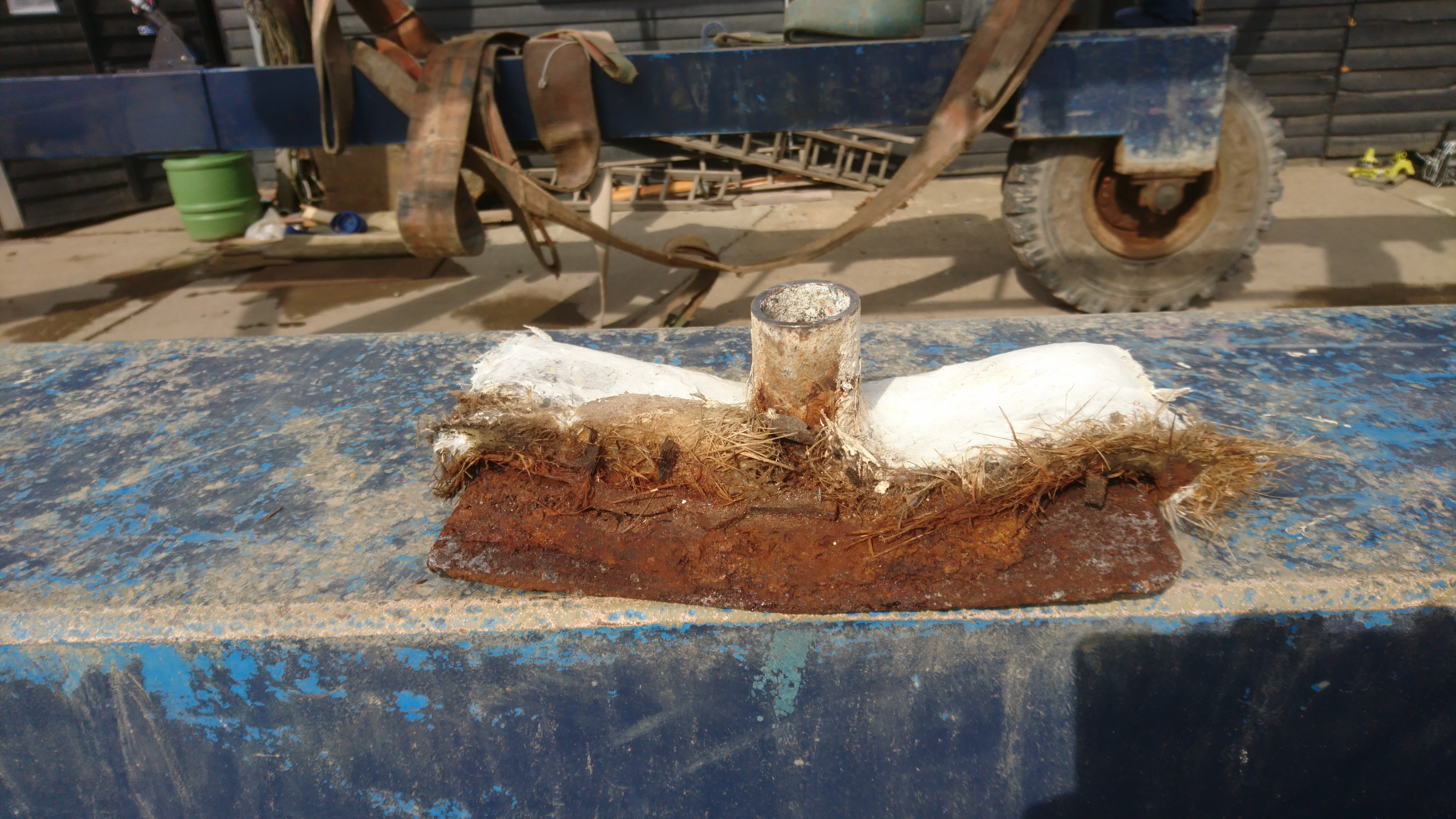
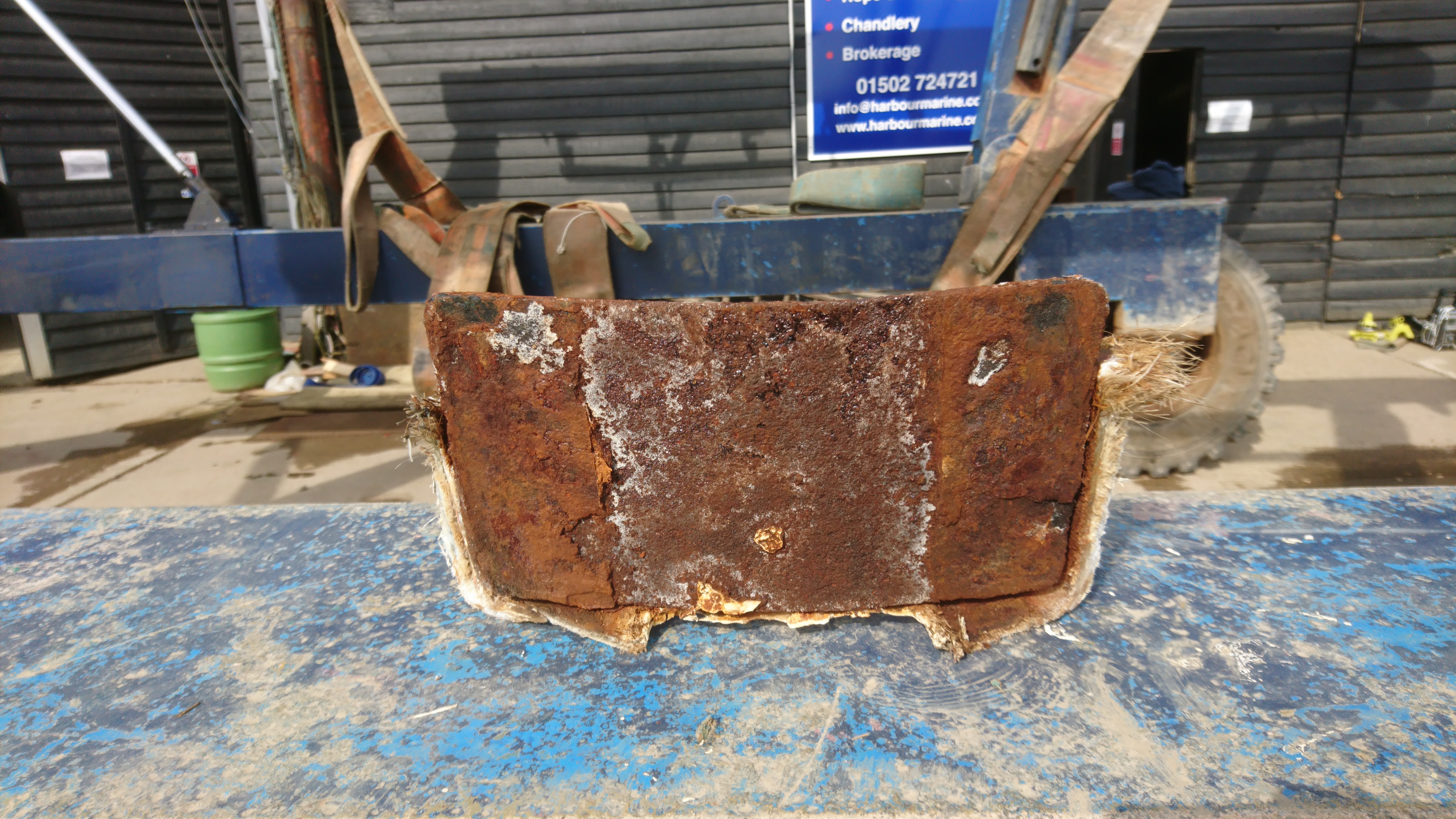
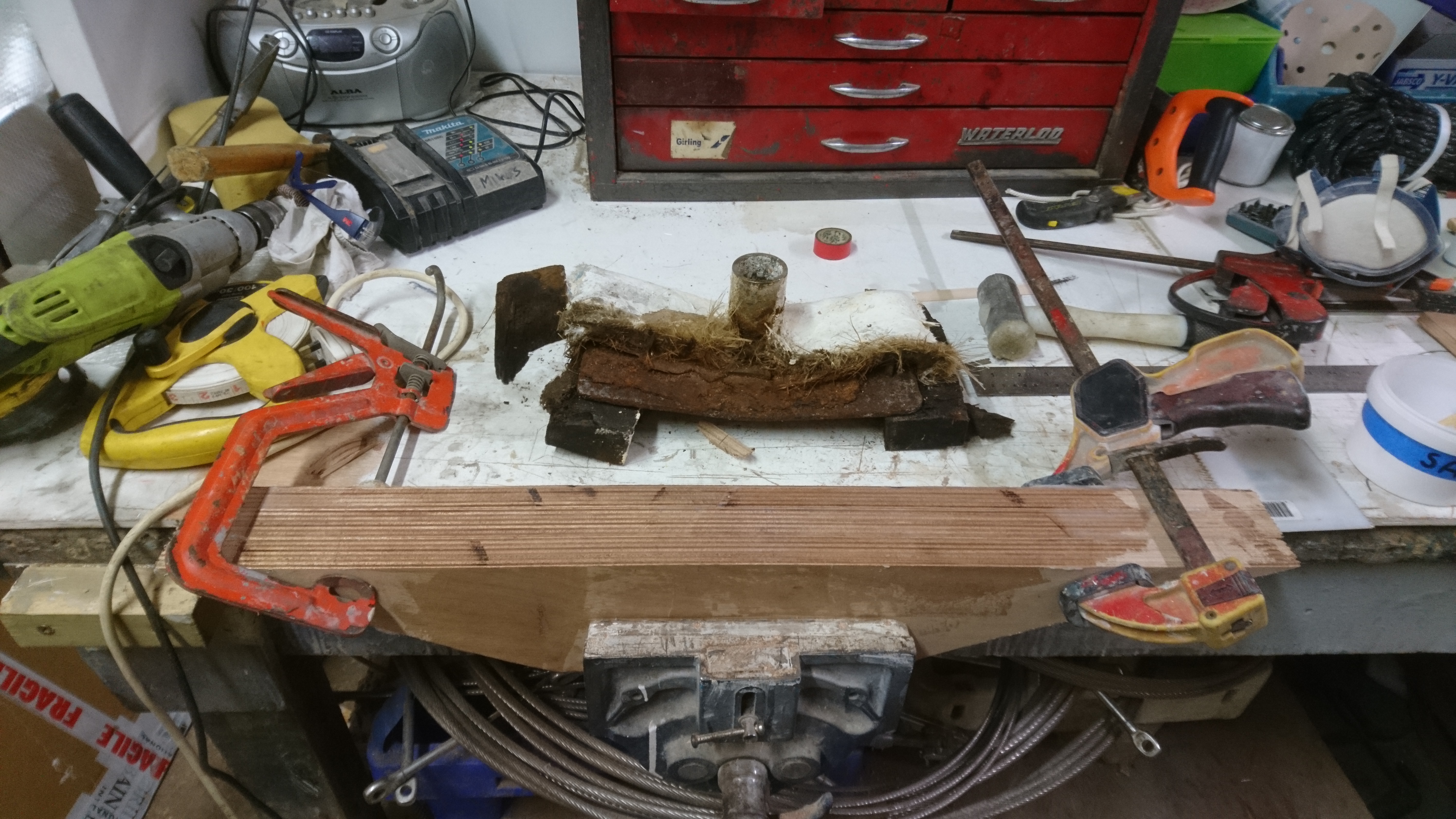
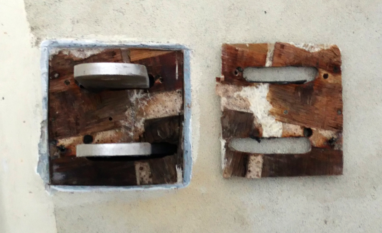
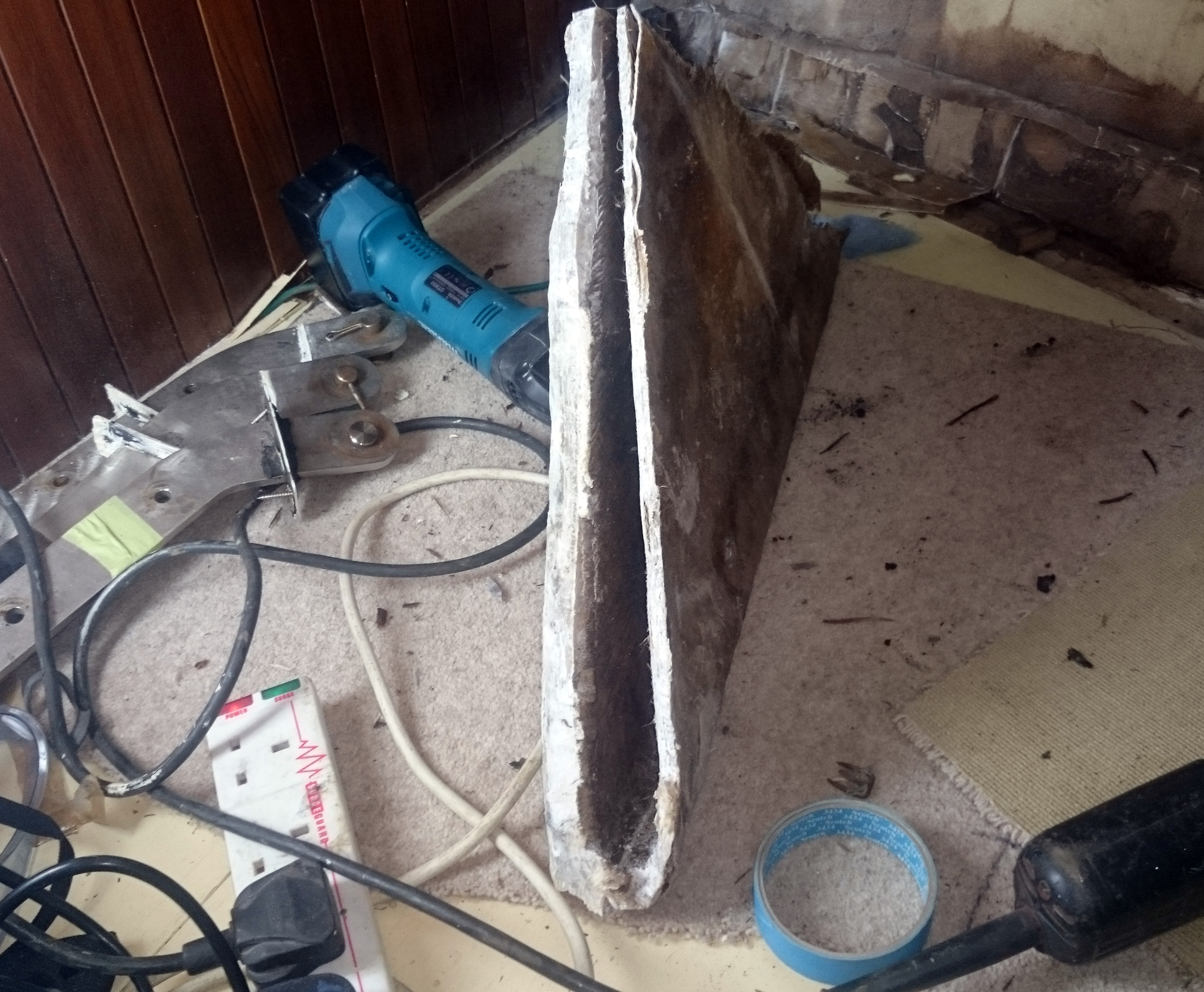
The post was made of 2″ galvanized steel tube with a 6mm plate welded to each end.
Interestingly there were no fasteners of any kind attaching the lower plate to anything, relying purely on a couple of layers of glass fibre.
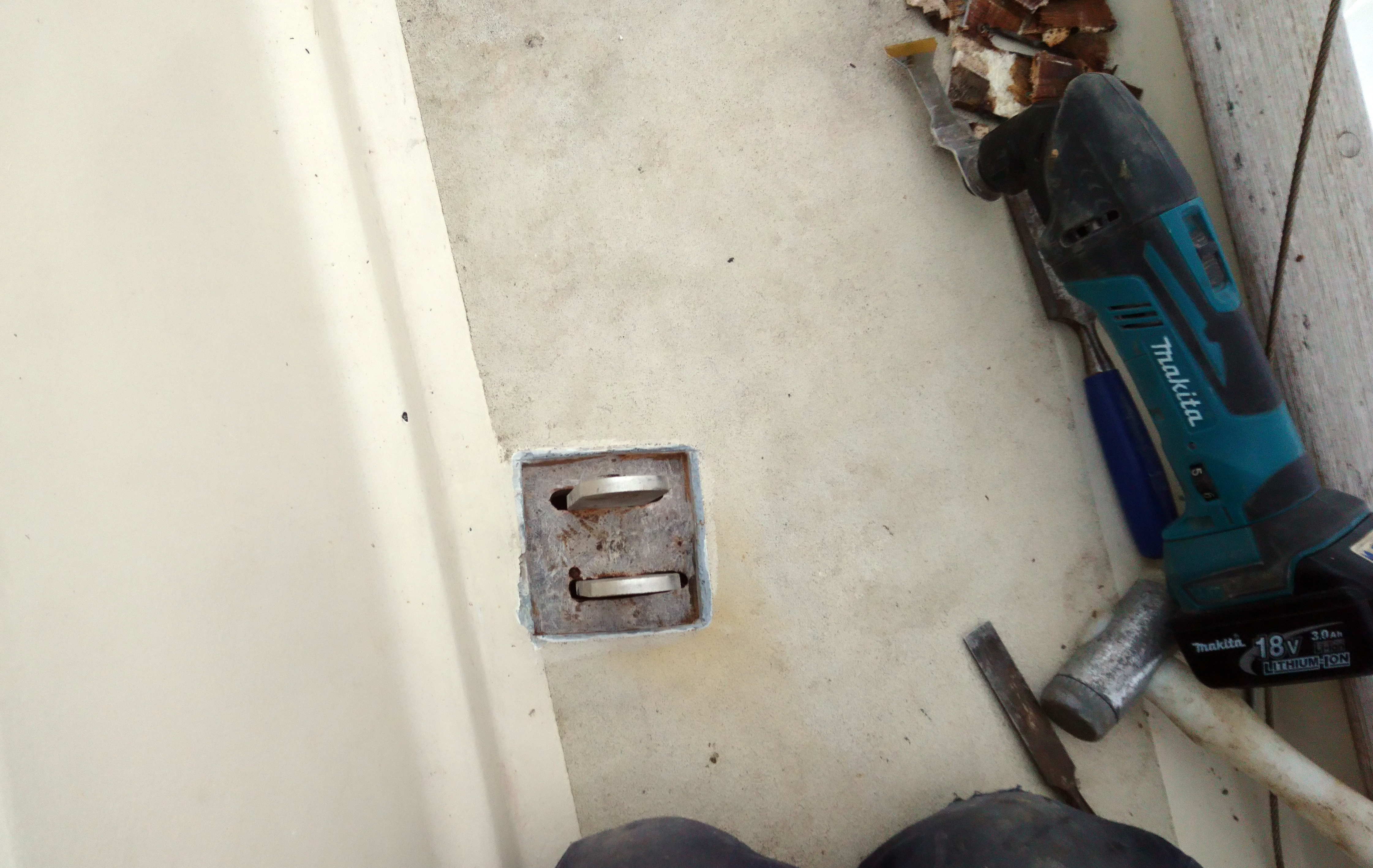
Apart from the lower 4″, the compression post was in very good condition.

The 9″ grinder with a slitting disc took care of cutting off the corroded 4″ of tube and base plate.
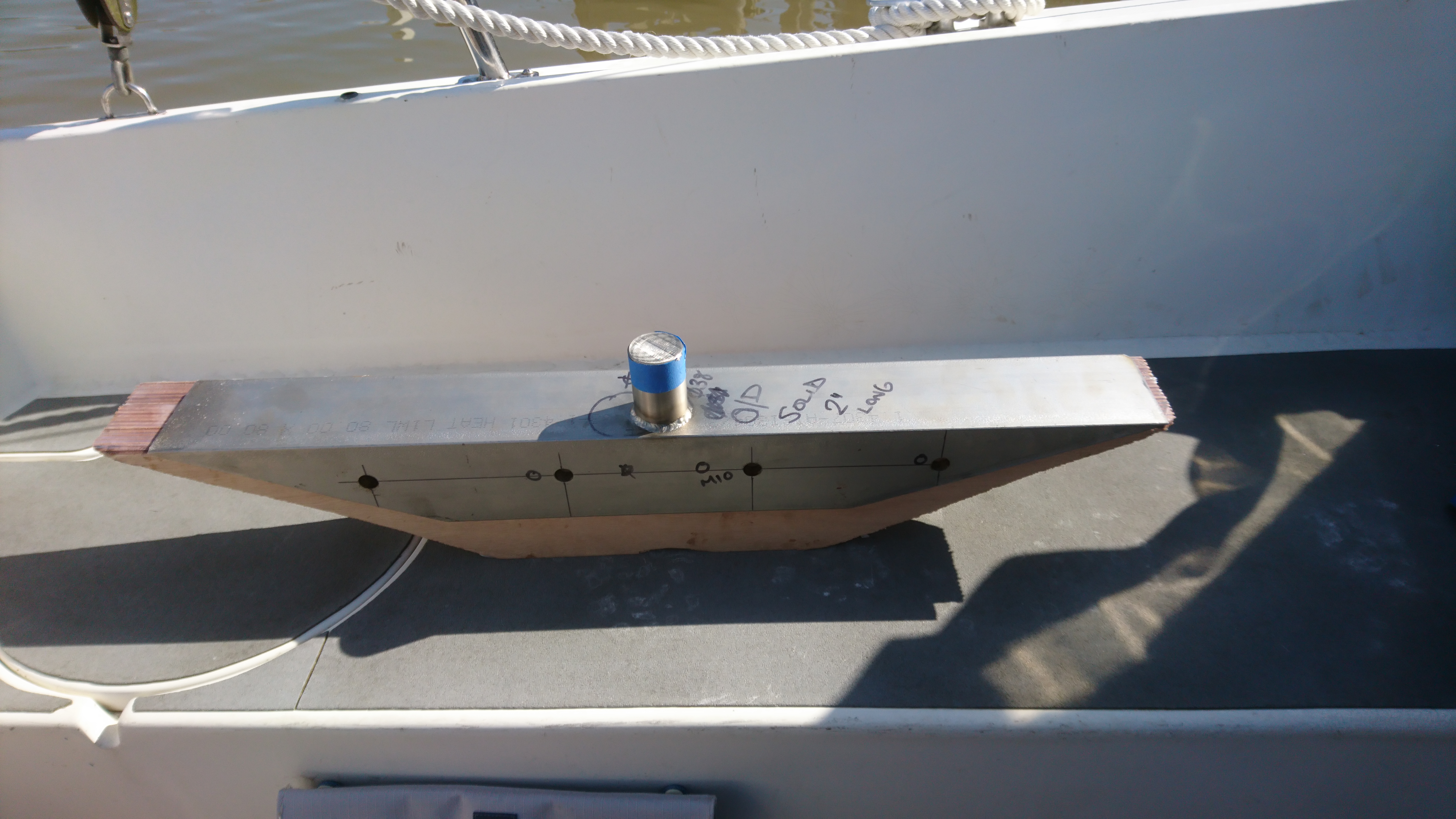
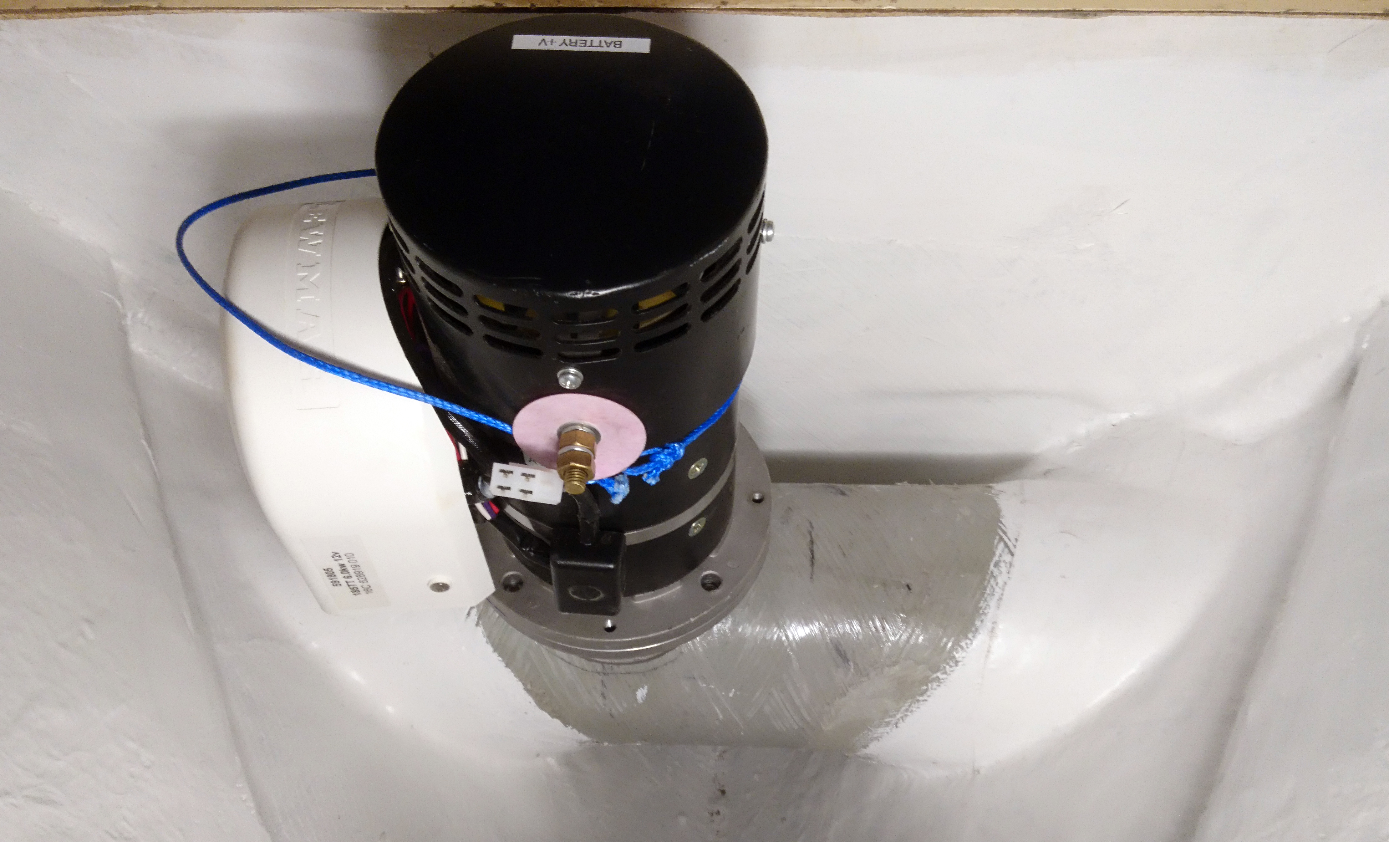
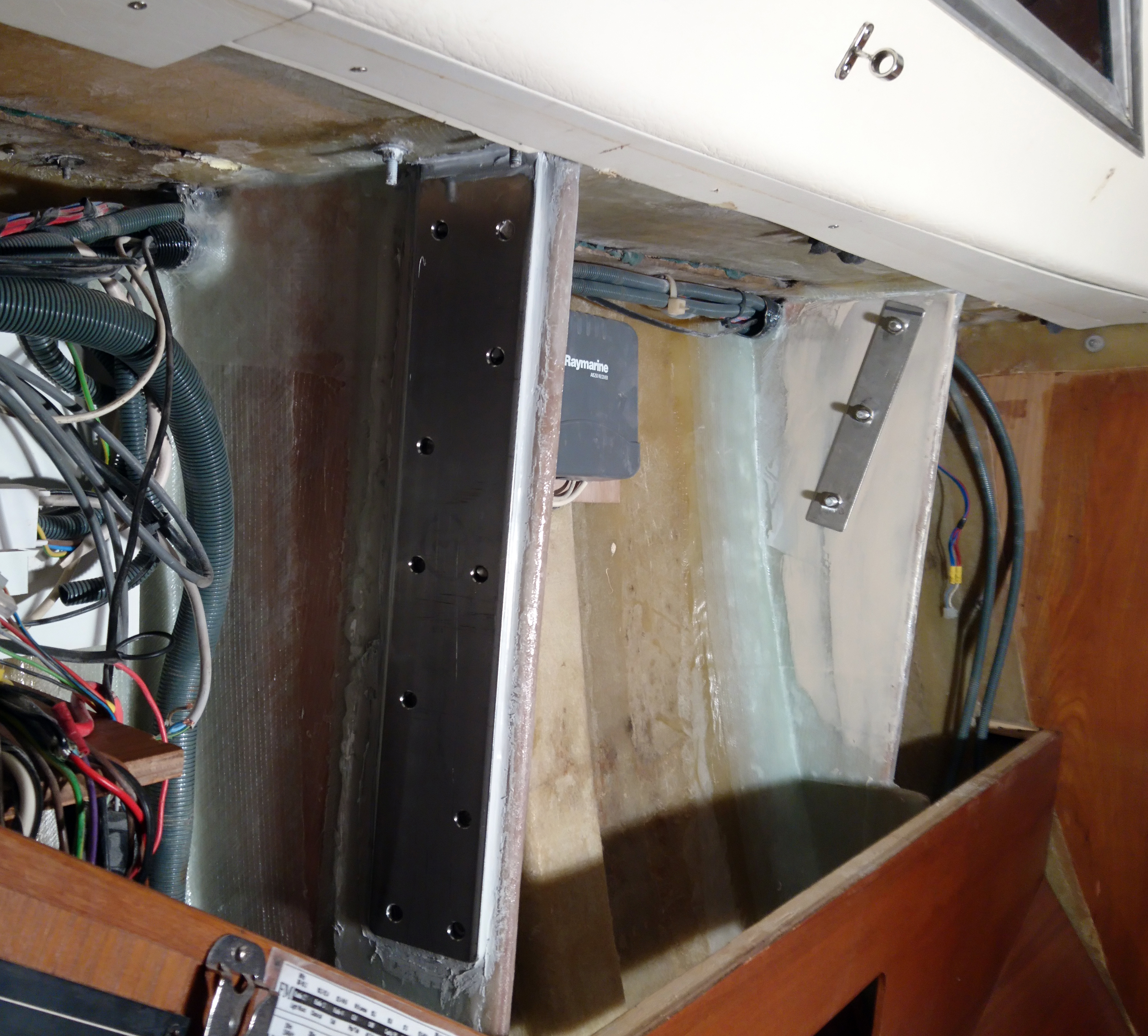
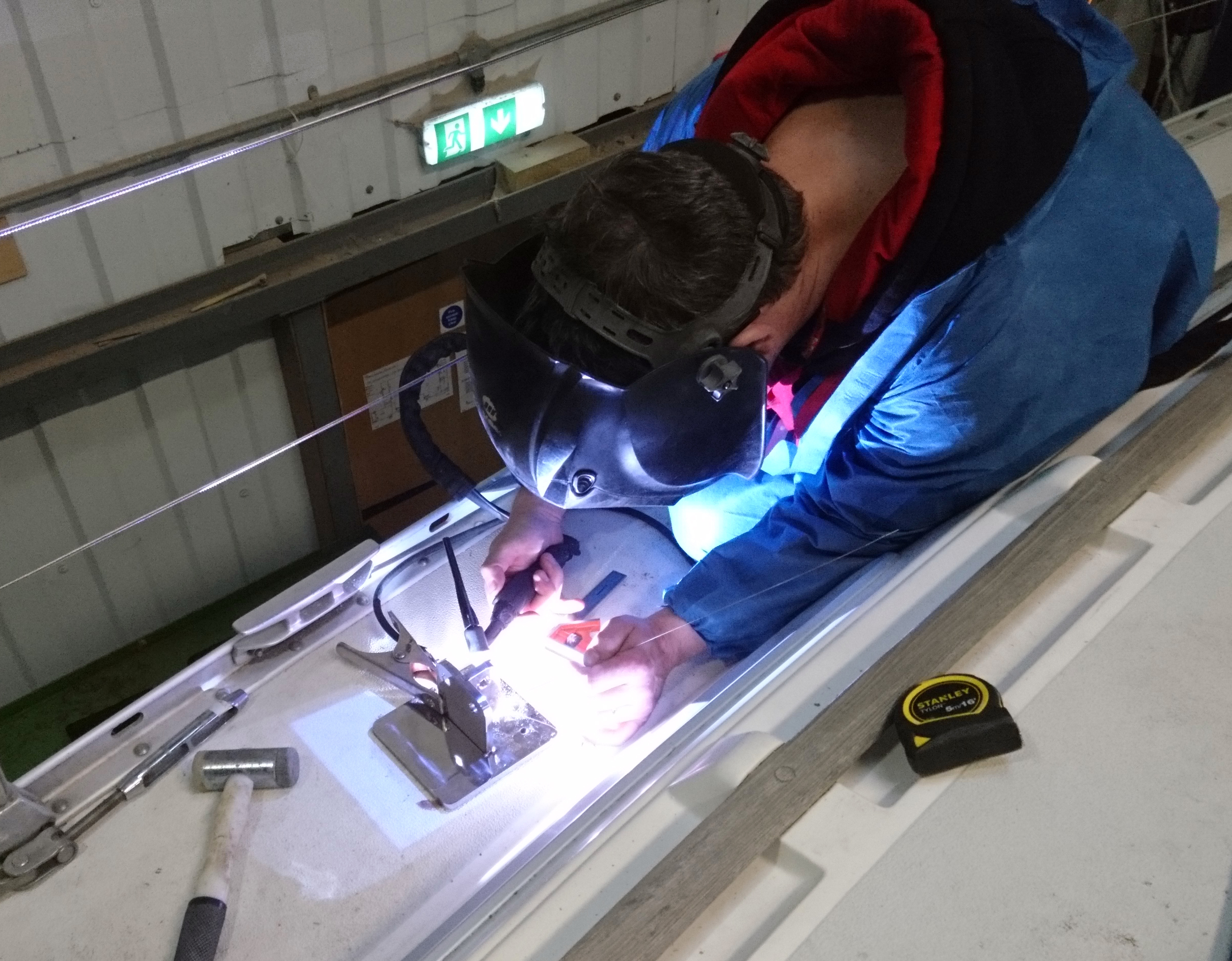
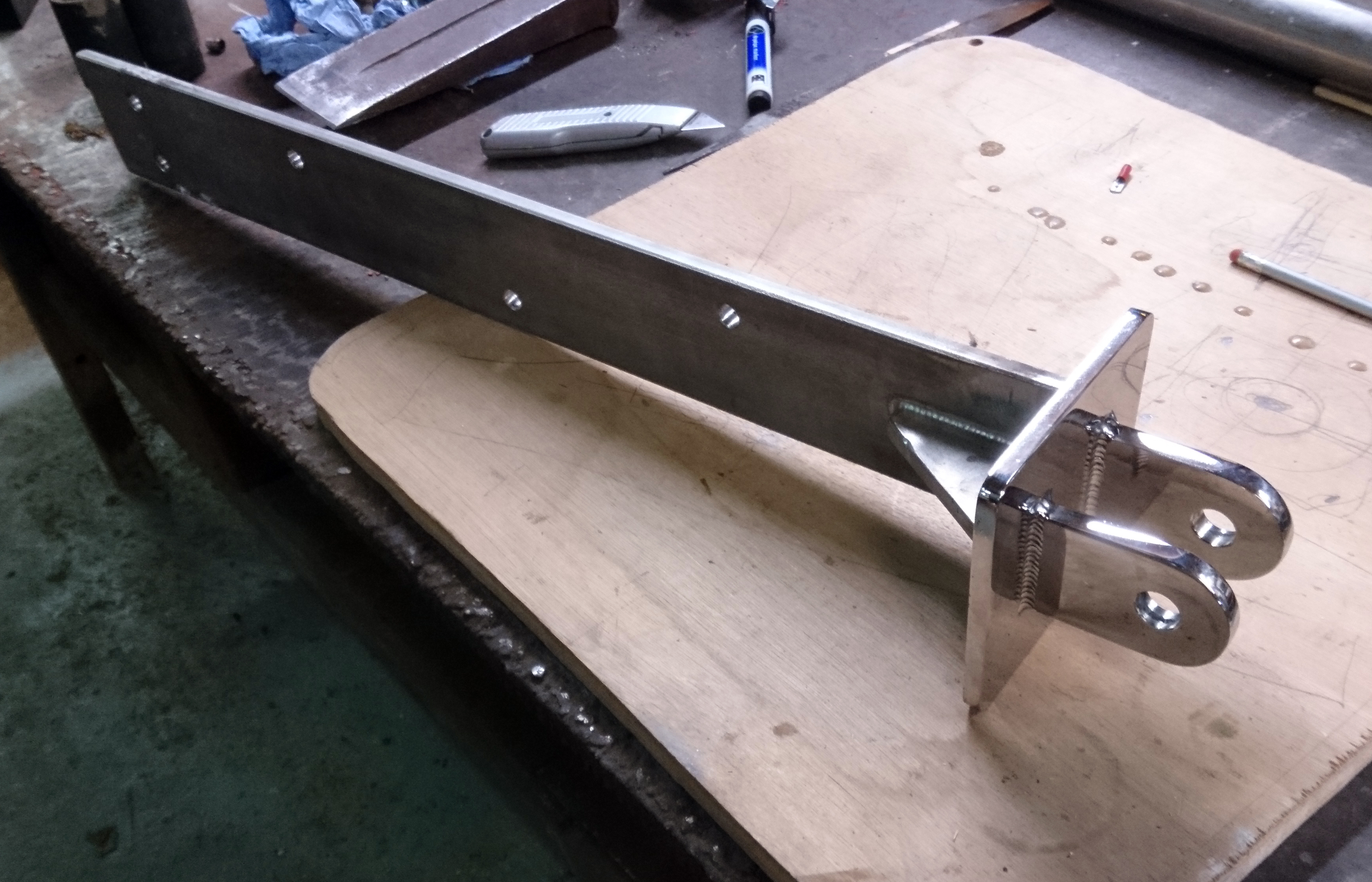
Welding galvanised steel is not a good idea at the best of times and access for welding in the boat was also not good, so I decided to make the new base with a spigot that would slide up the inside of the main tube.

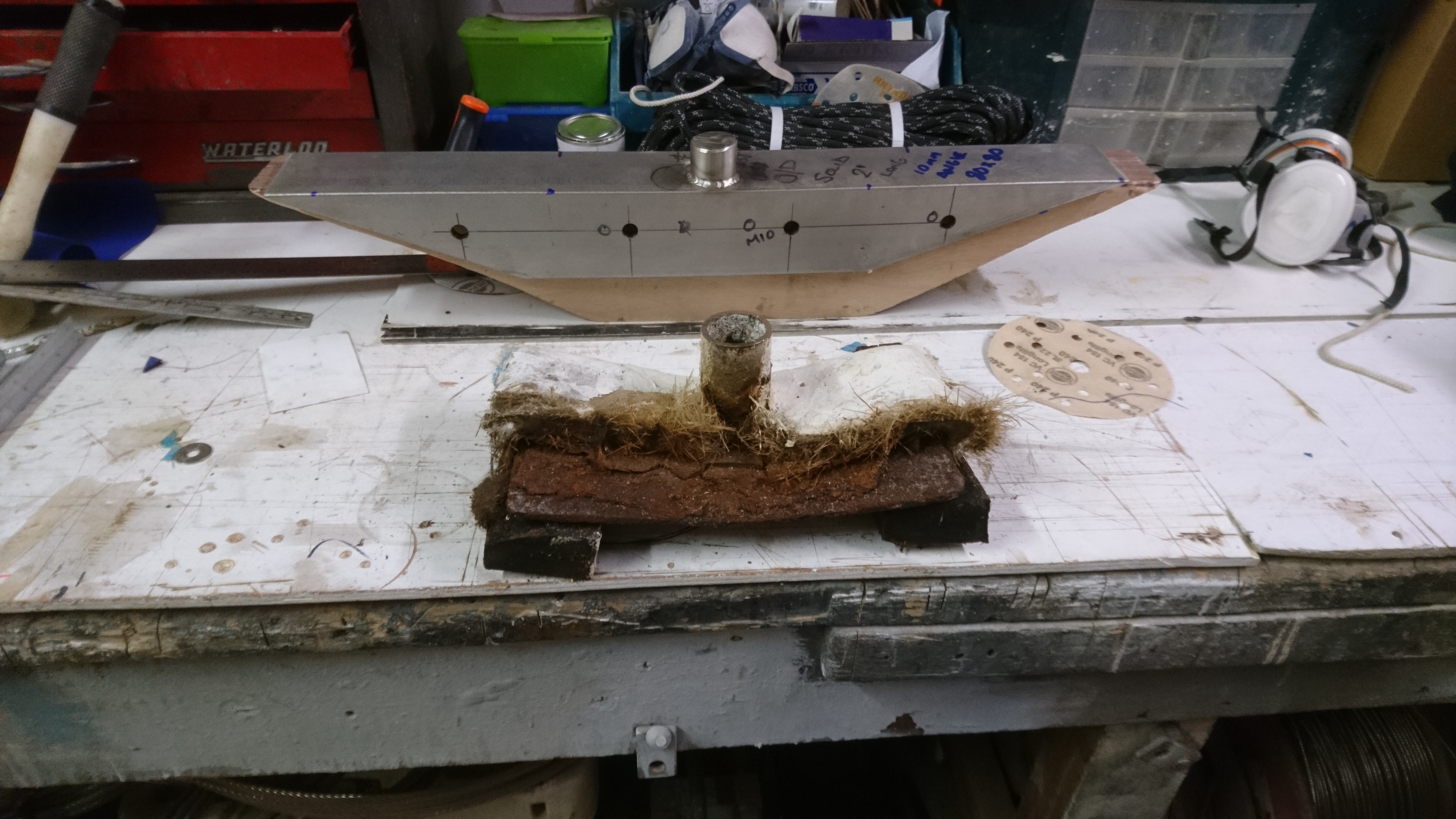
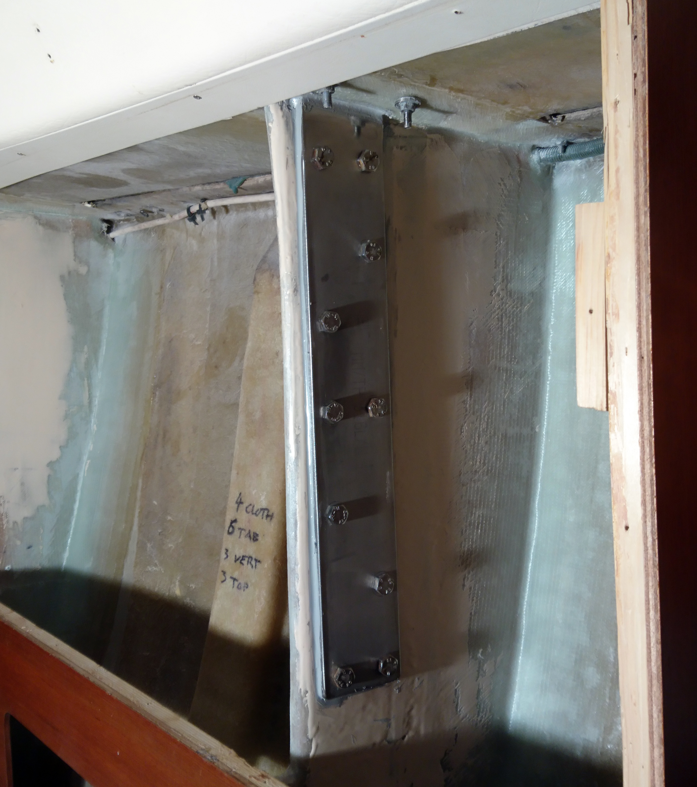
Luck was with me as the engineering dept had been fitting new engine beds to a 46′ classic motor yacht and there was a some 80x80x10 stainless angle left over that was just the right length.
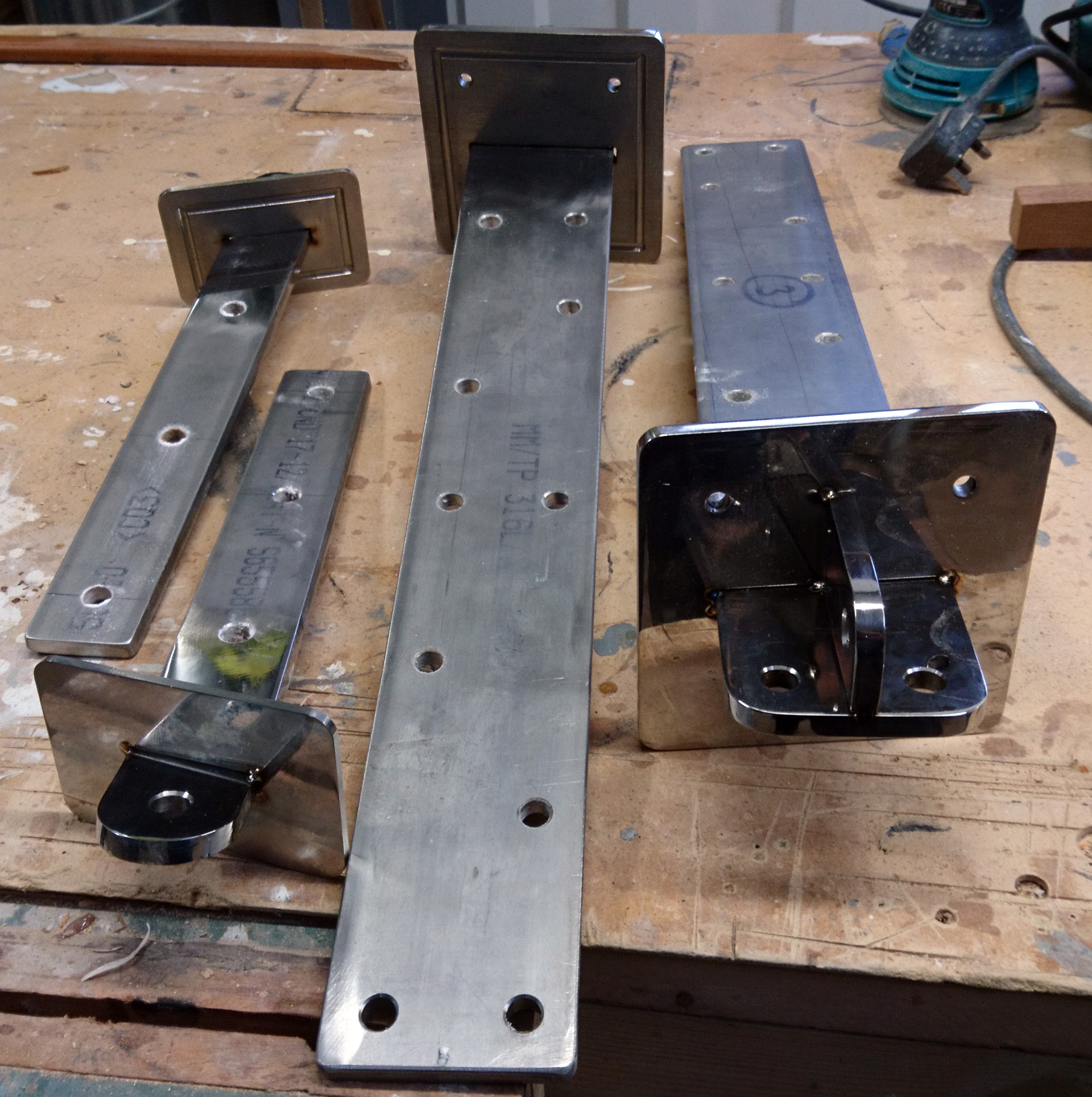
We chopped 3″ off an old 1 3/4″ propshaft and that was welded to the 316 ss angle to give us a spigot that fitted inside the post like a glove.
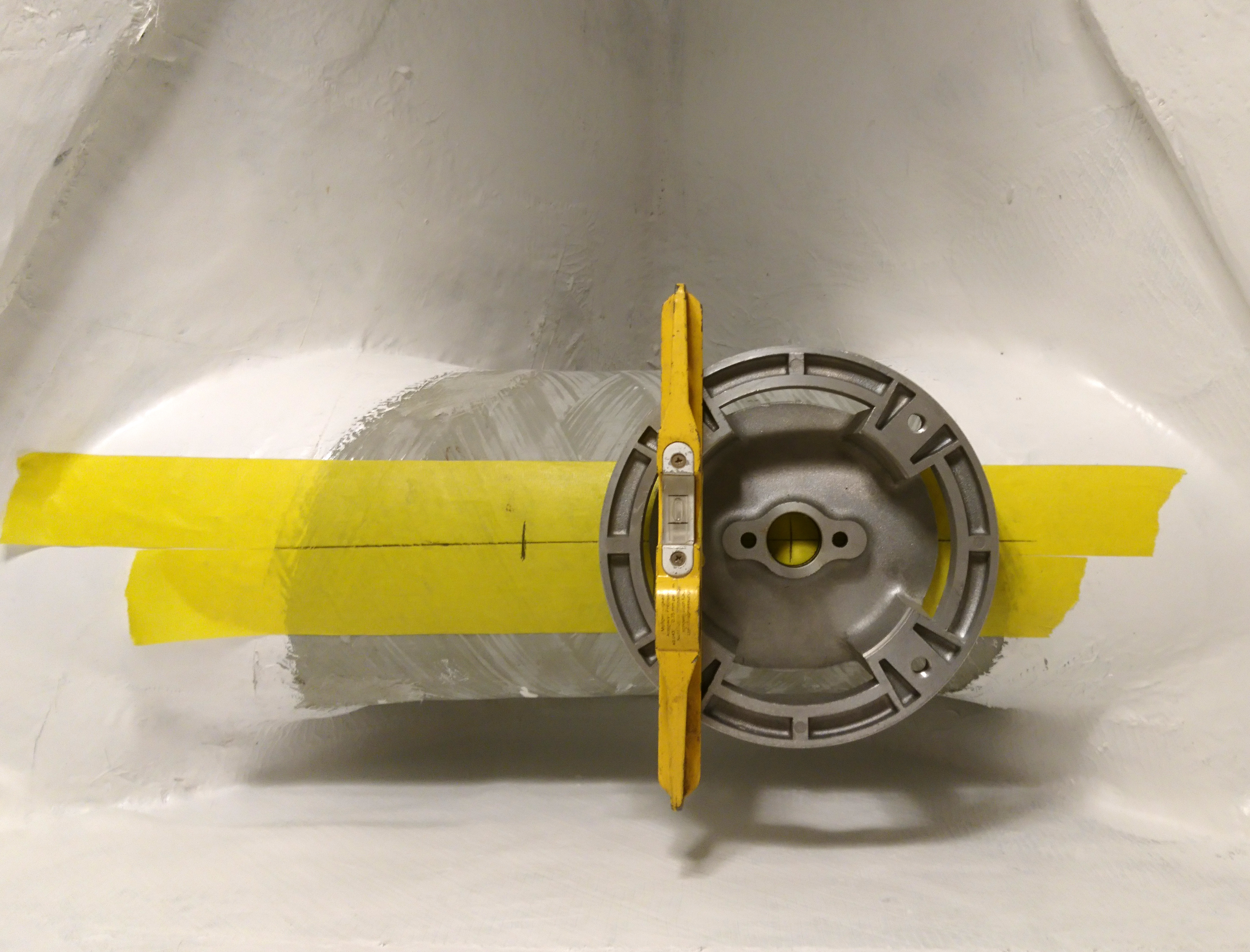
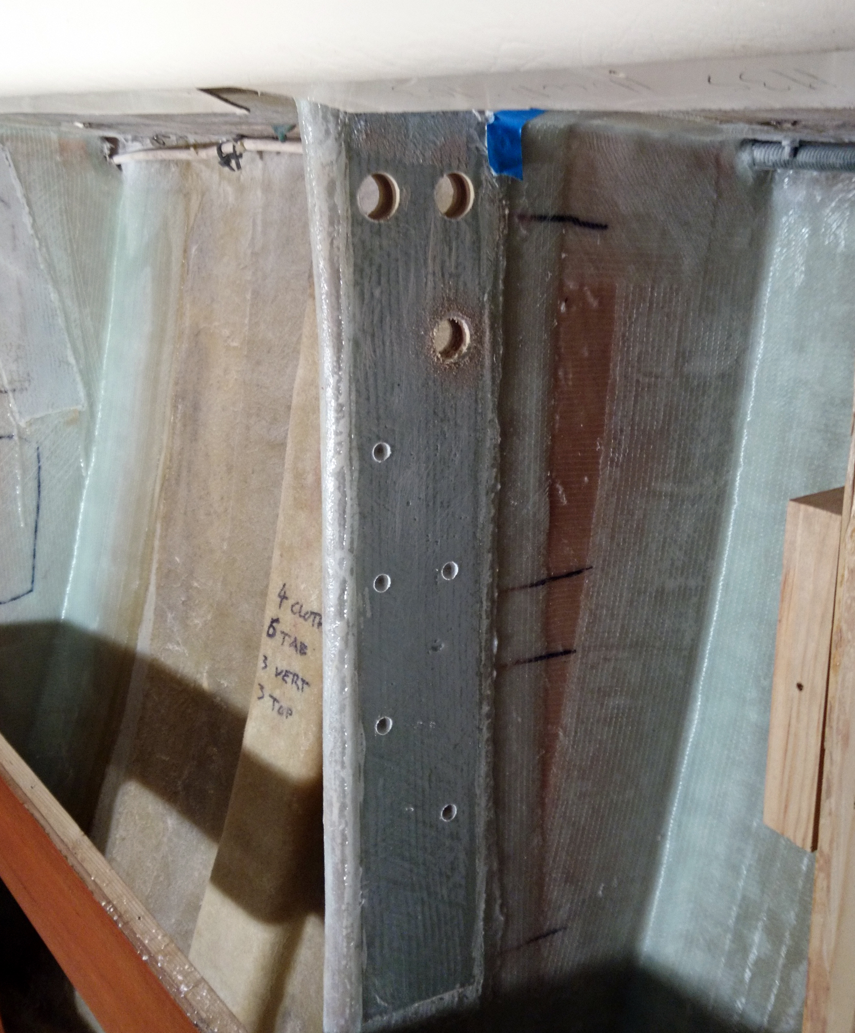
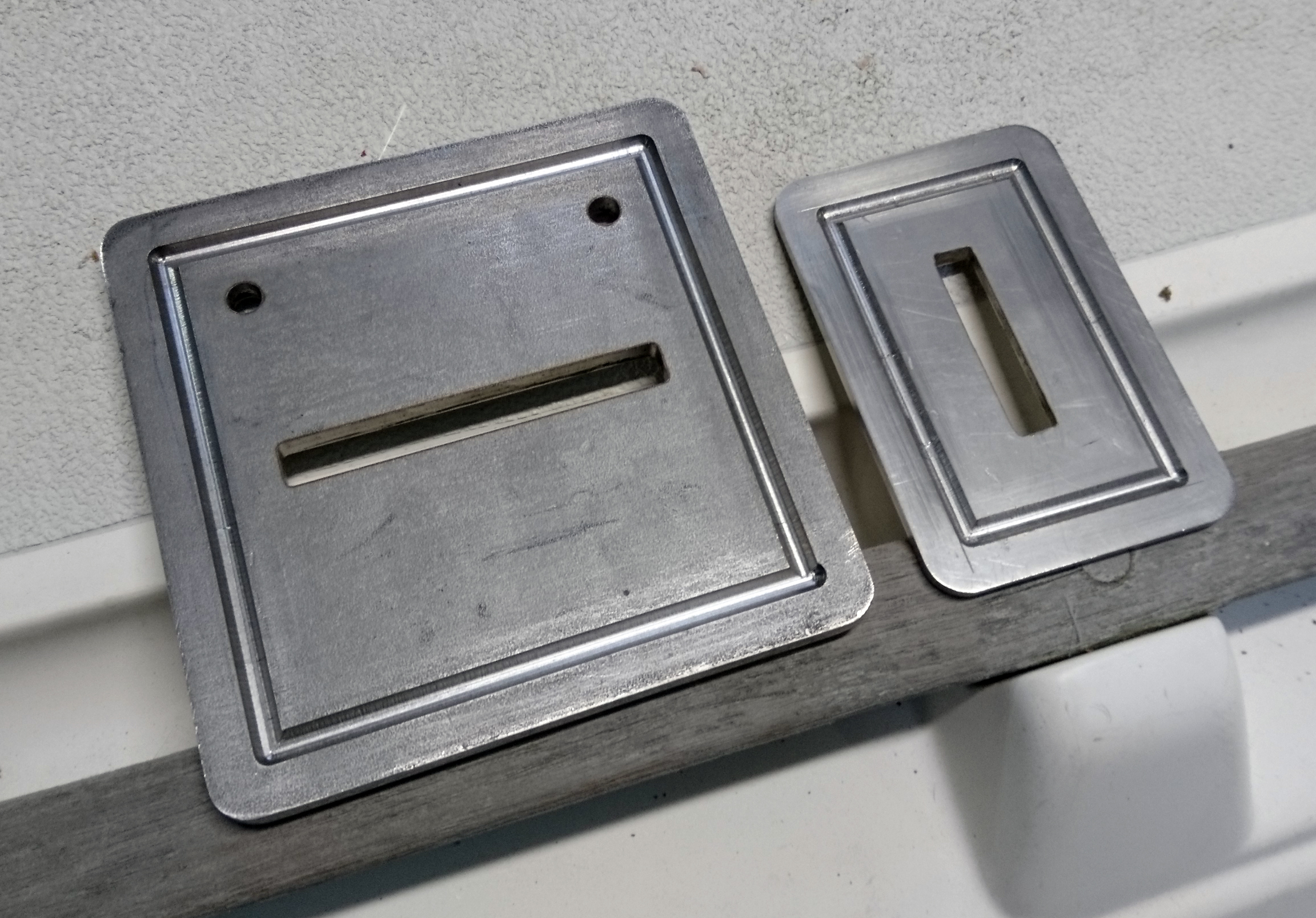
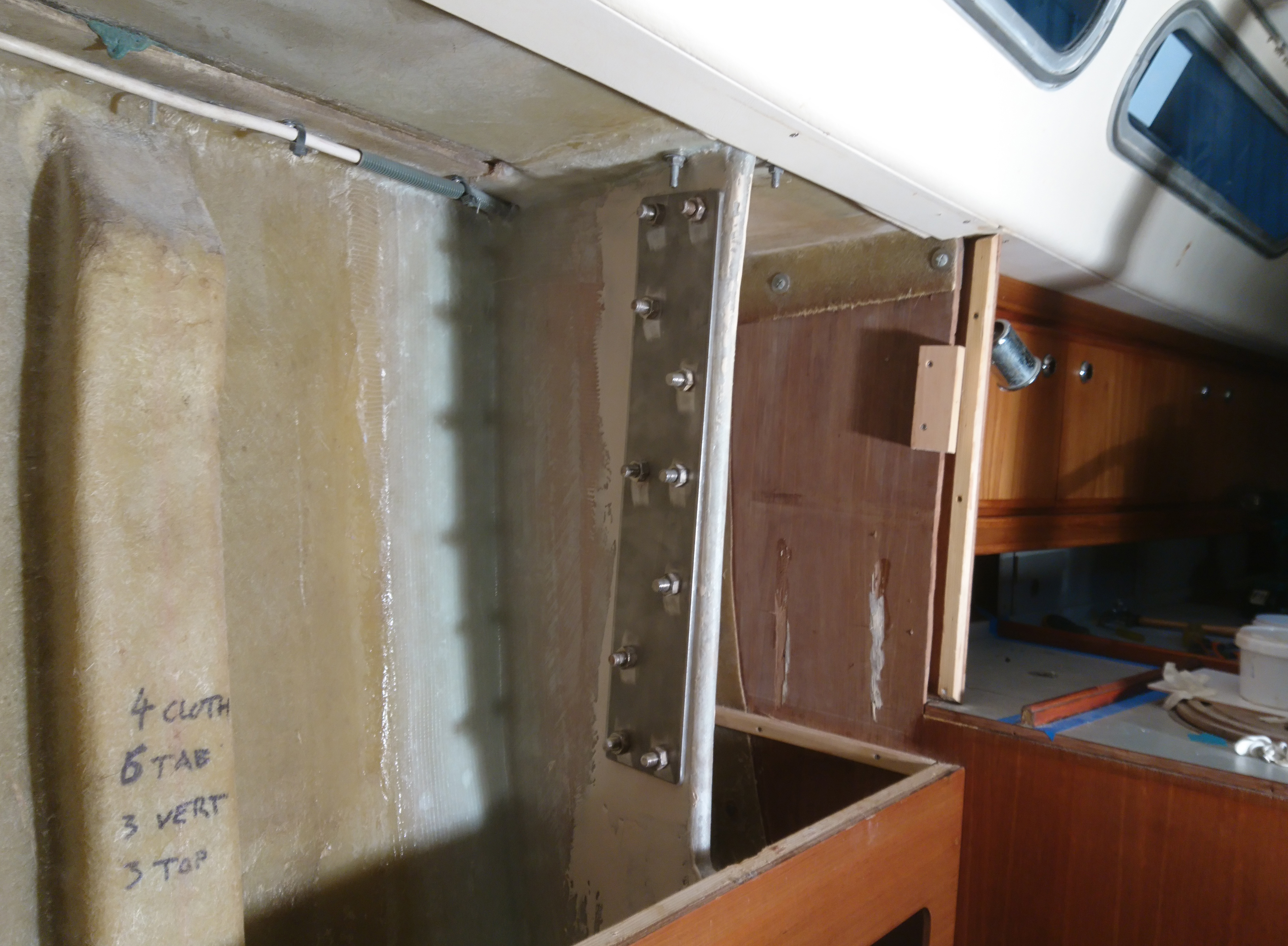
The whole assembly was to be bolted through the Saloon bulkhead so 4 x 10mm holes were drilled in the angle.

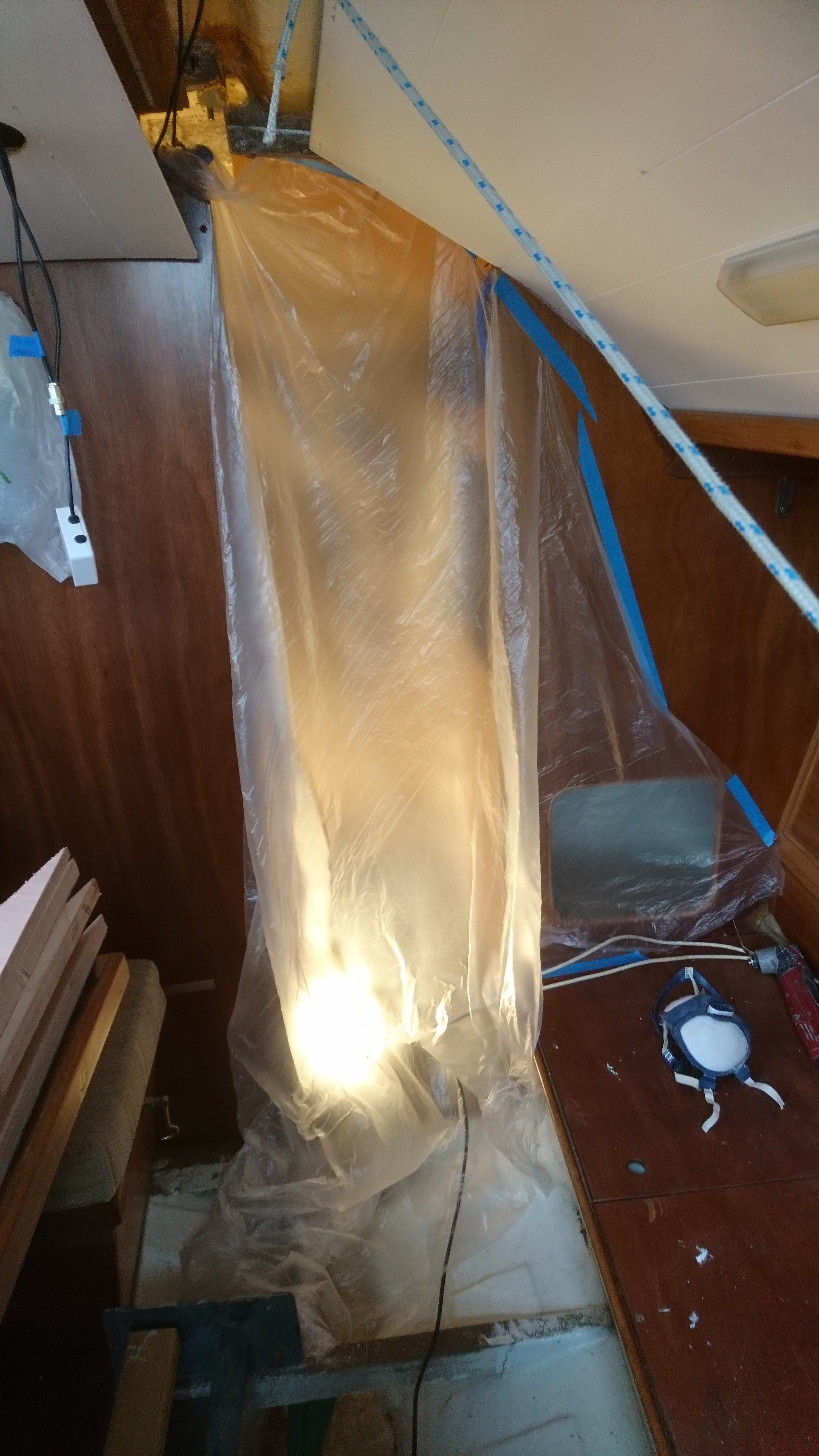
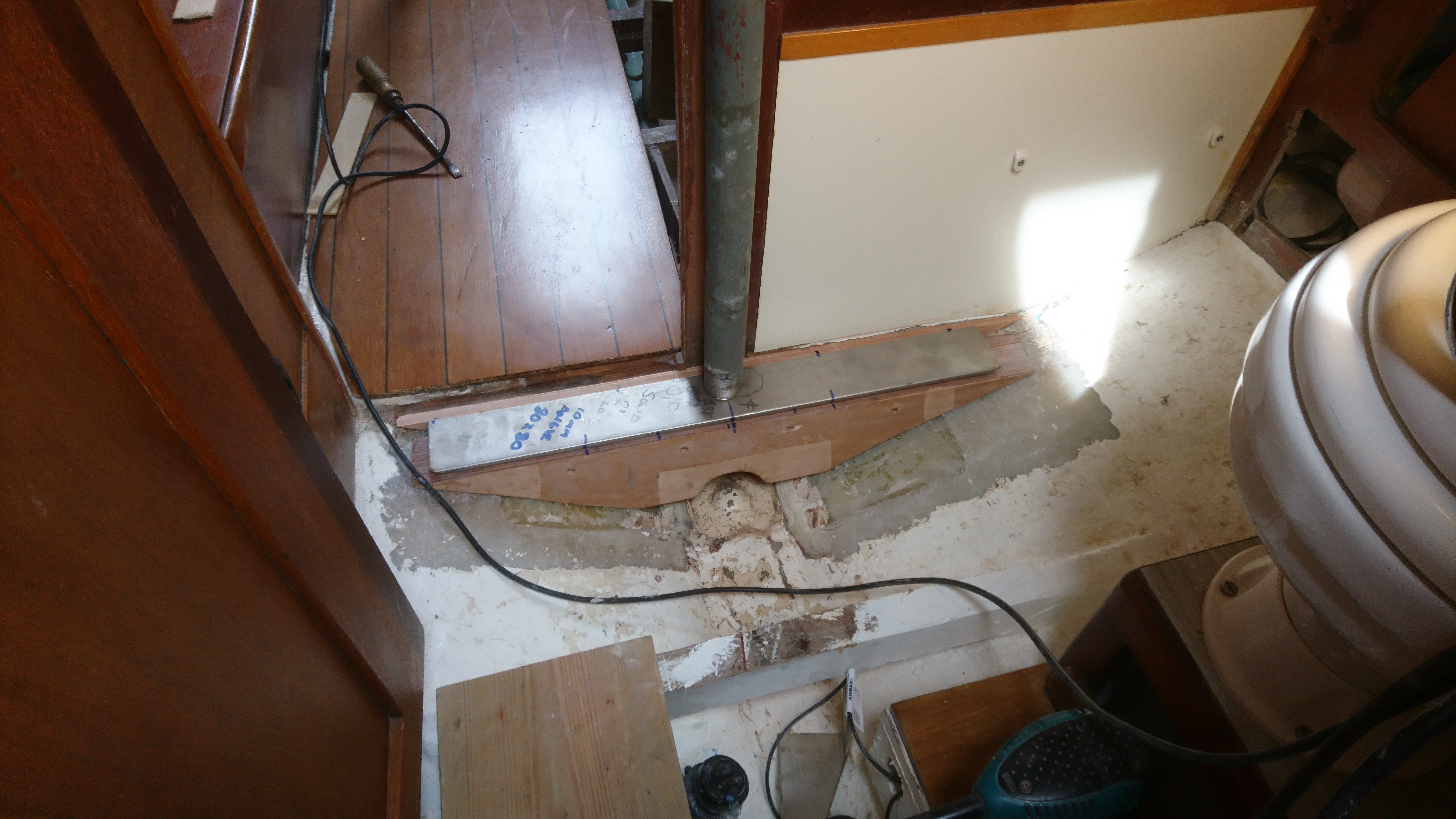
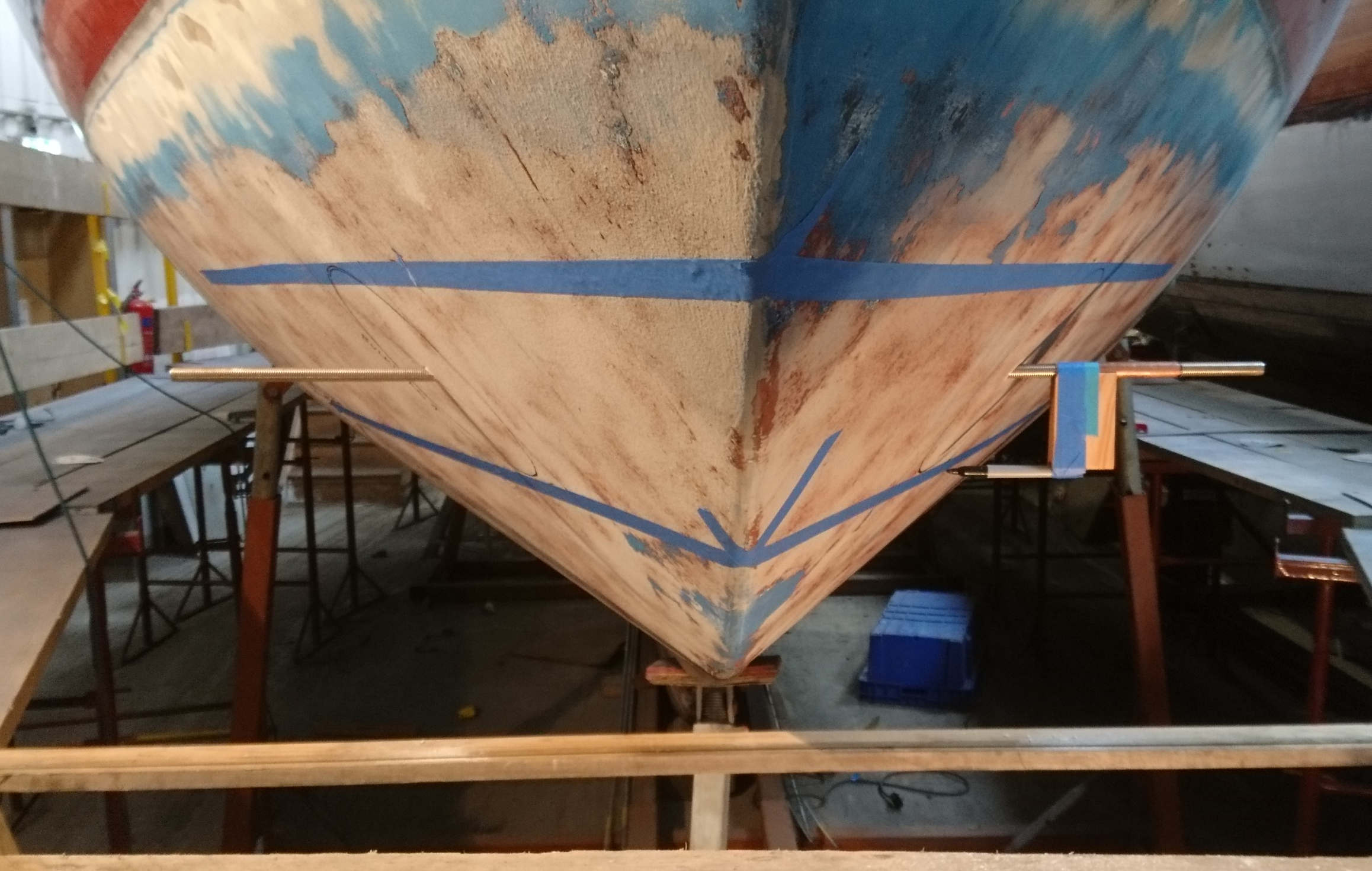
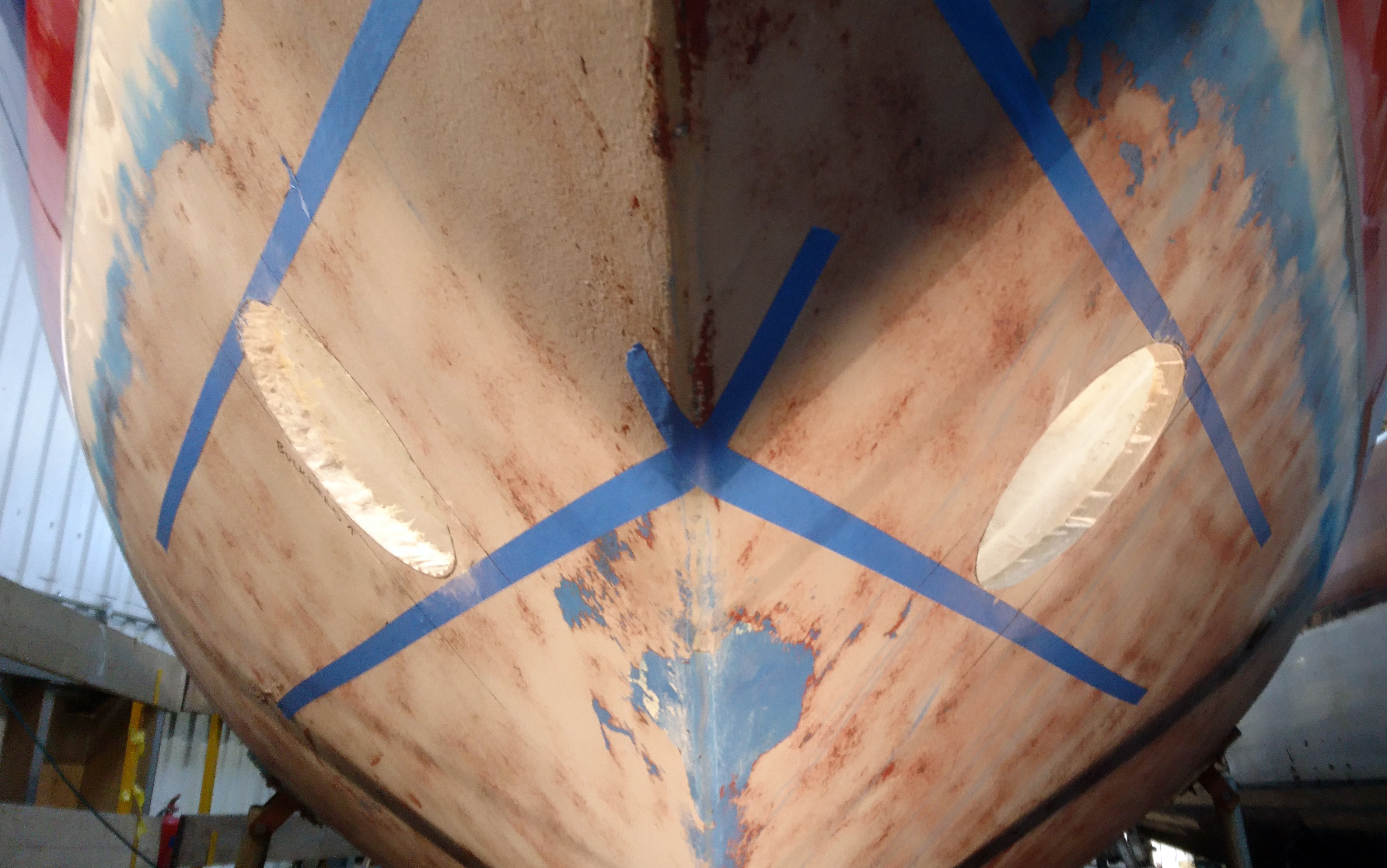
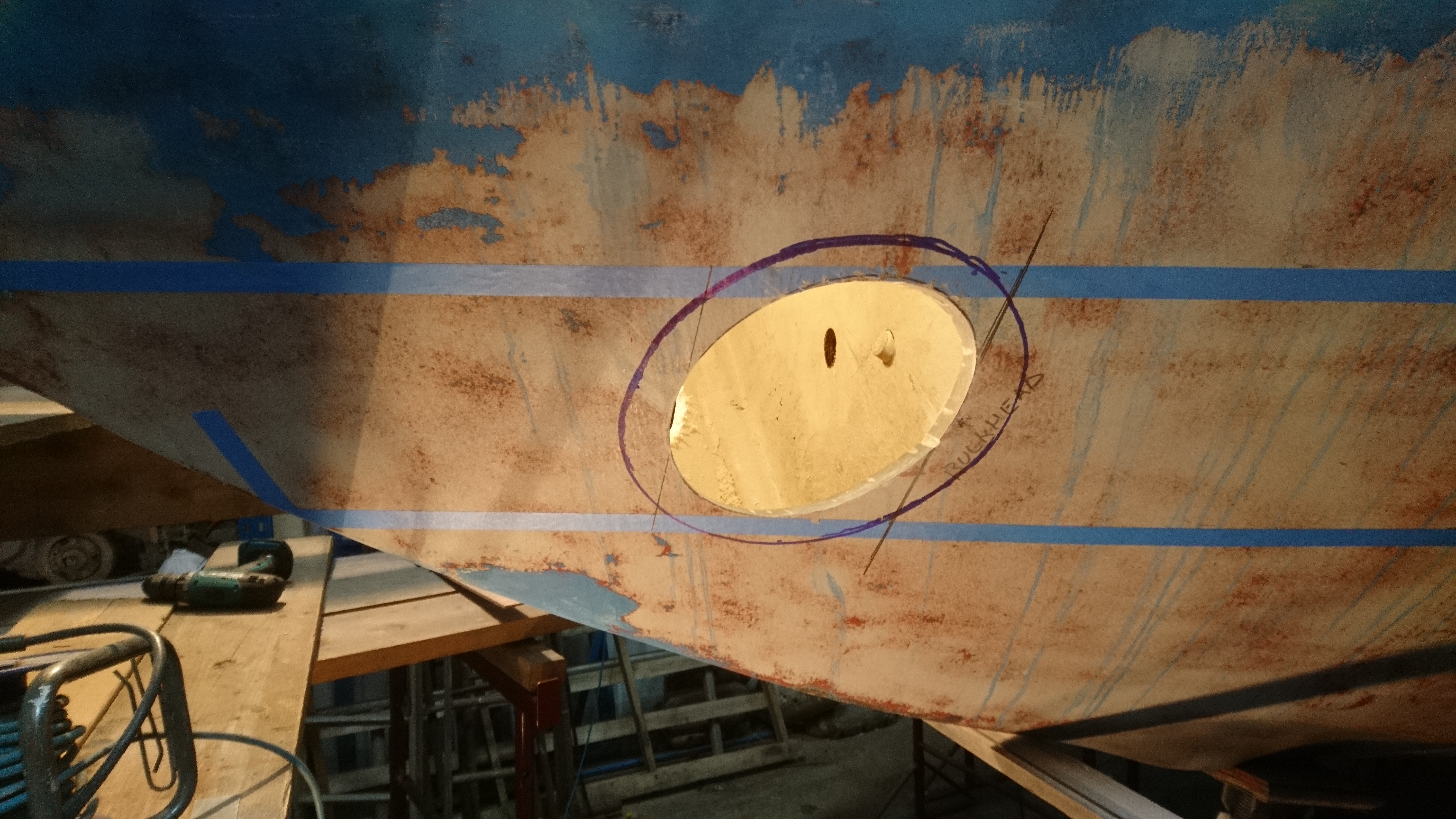
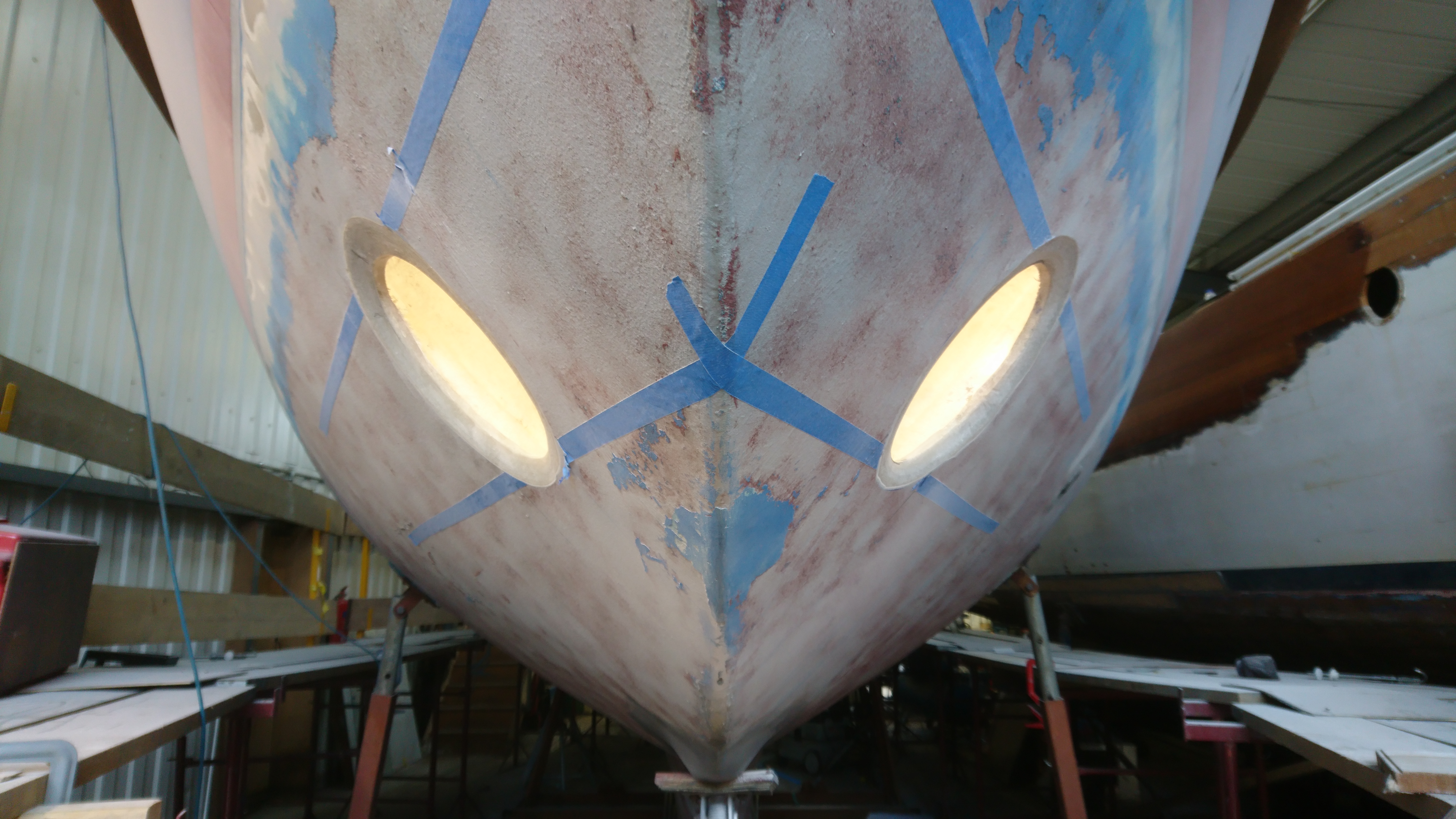
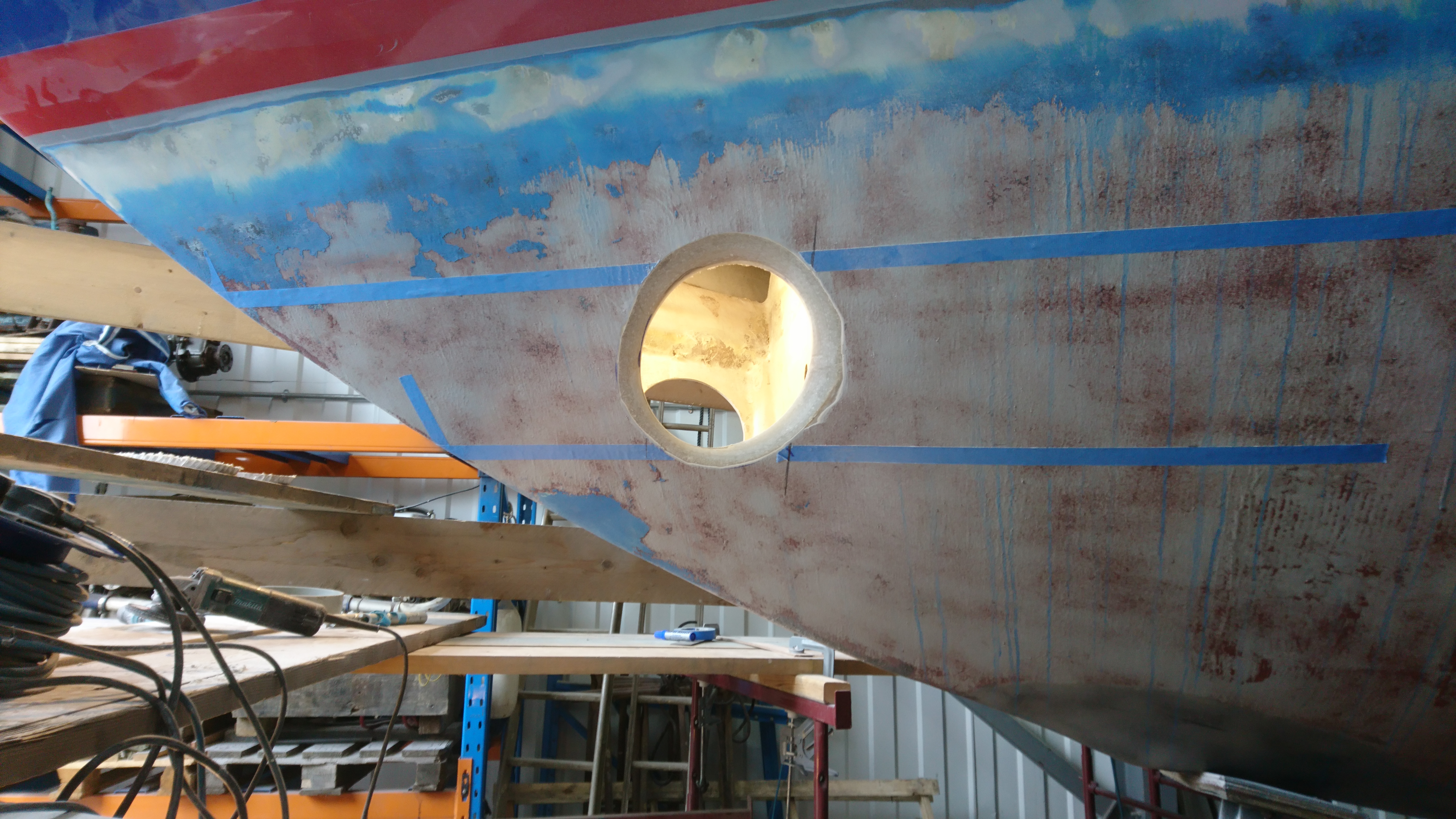
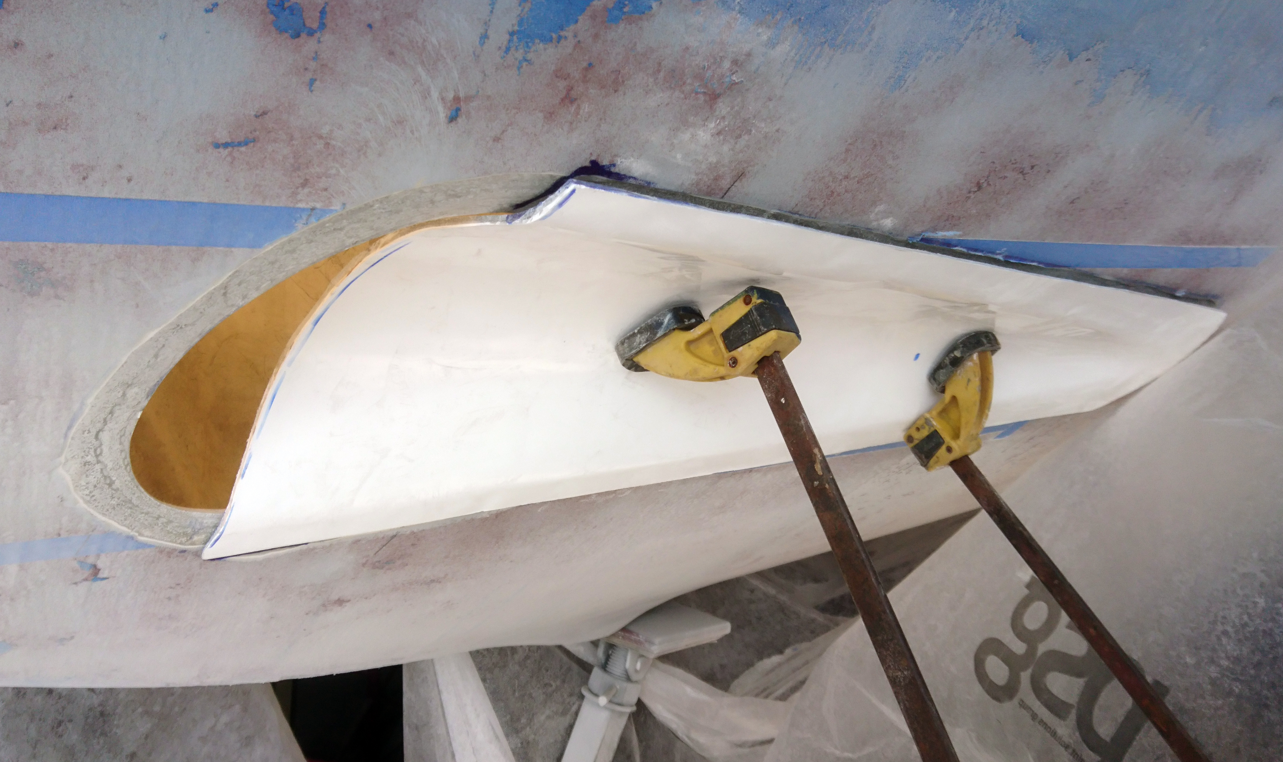
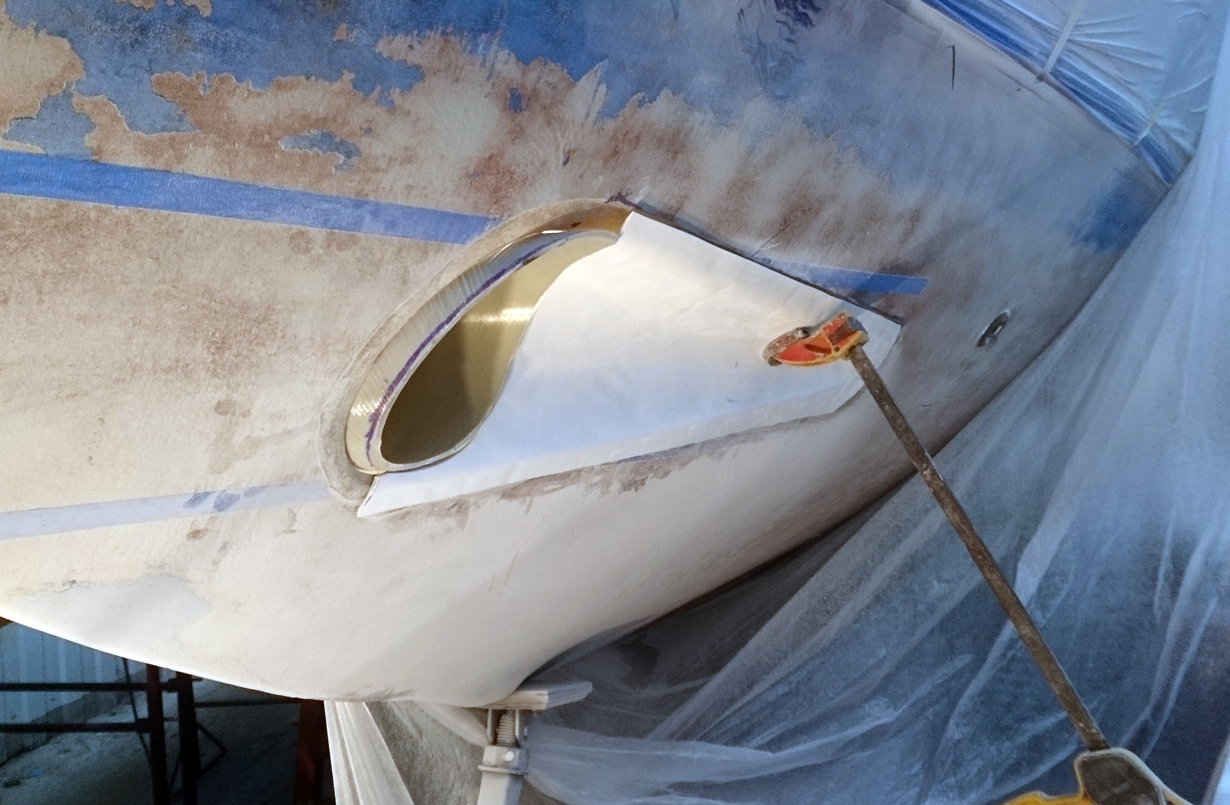
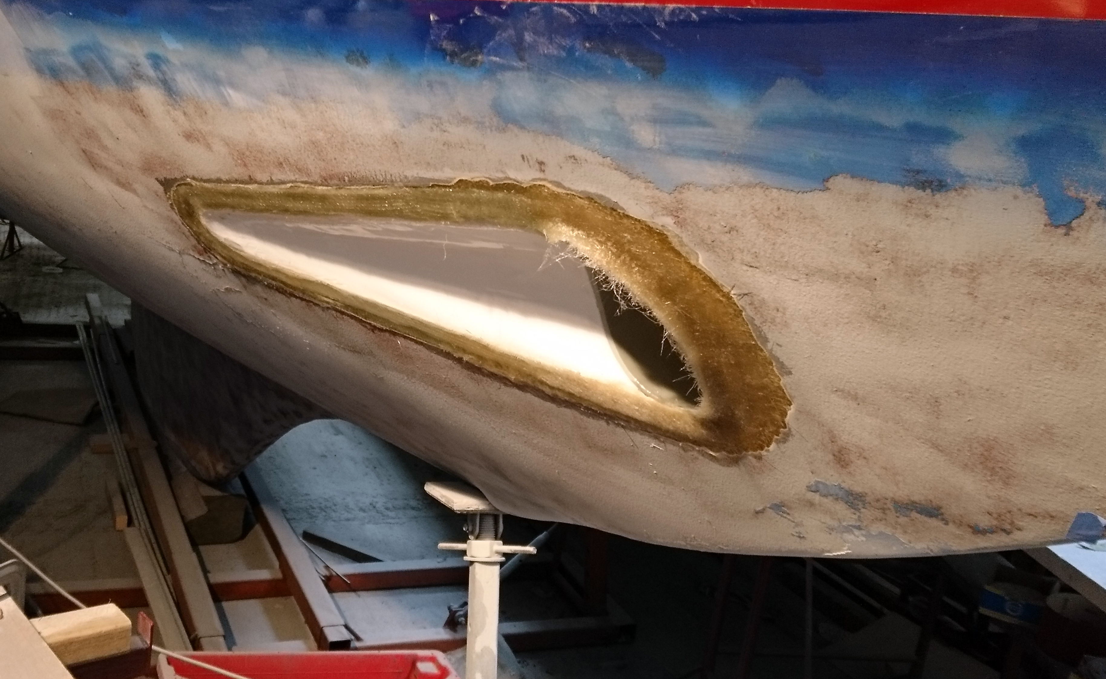
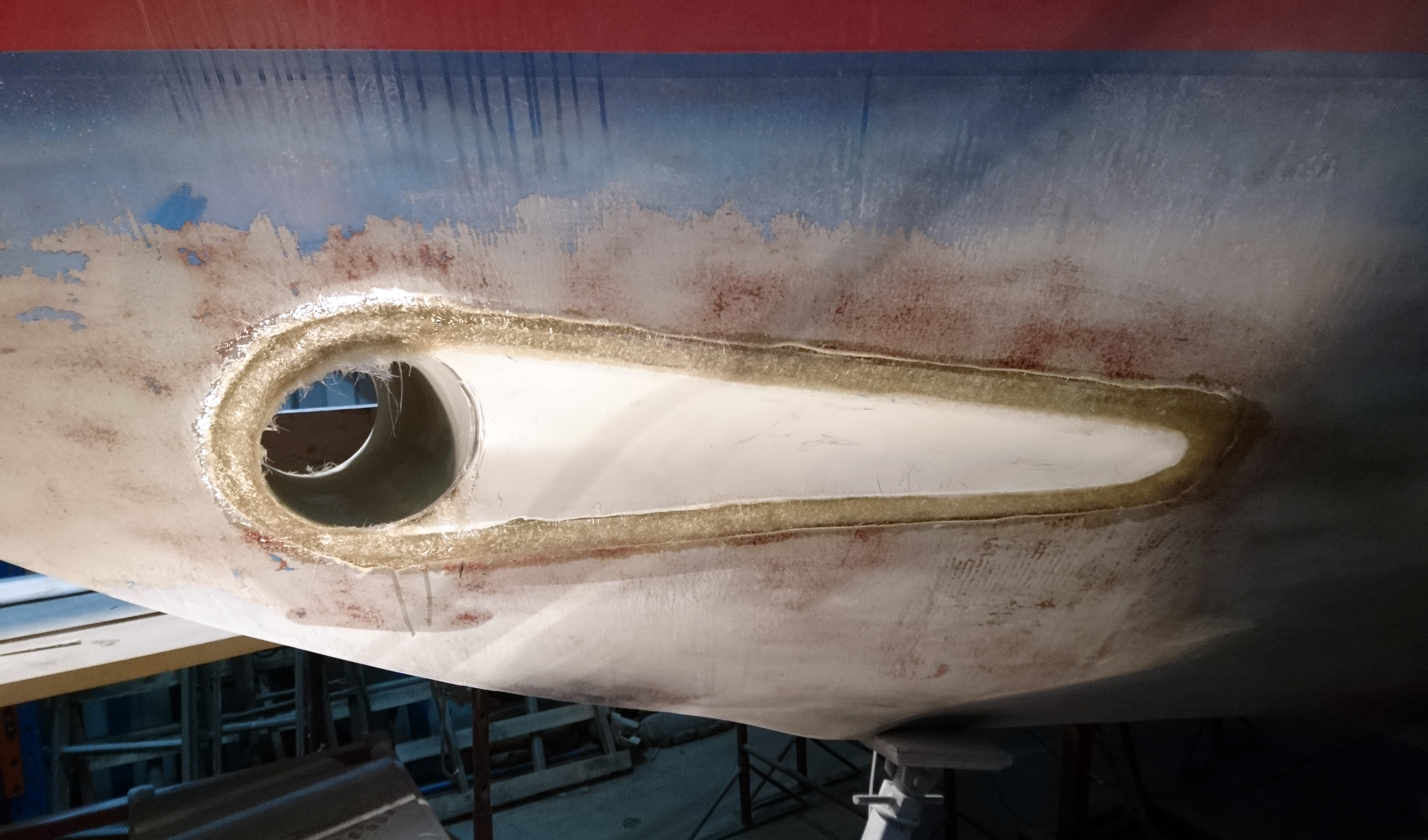
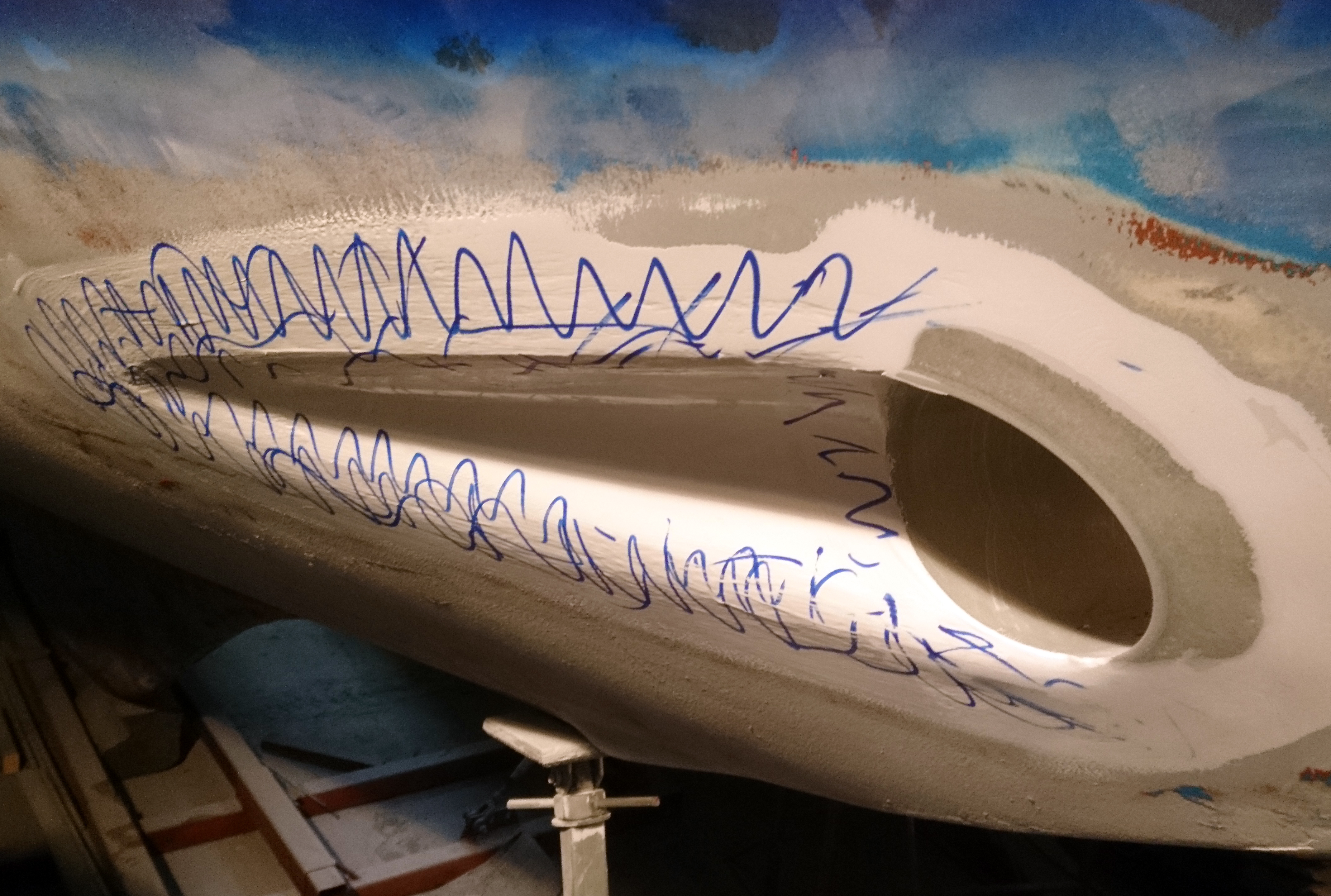
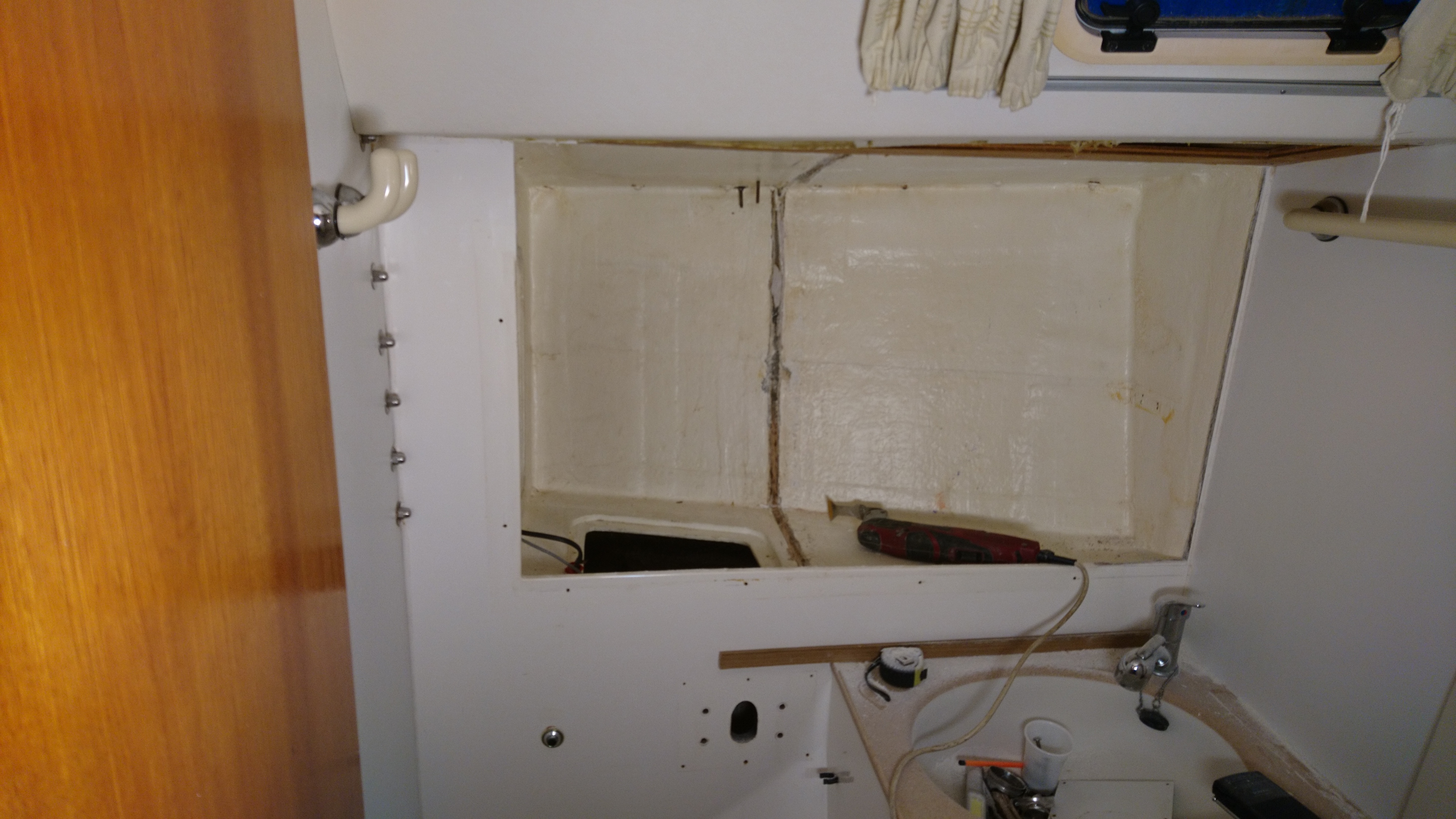
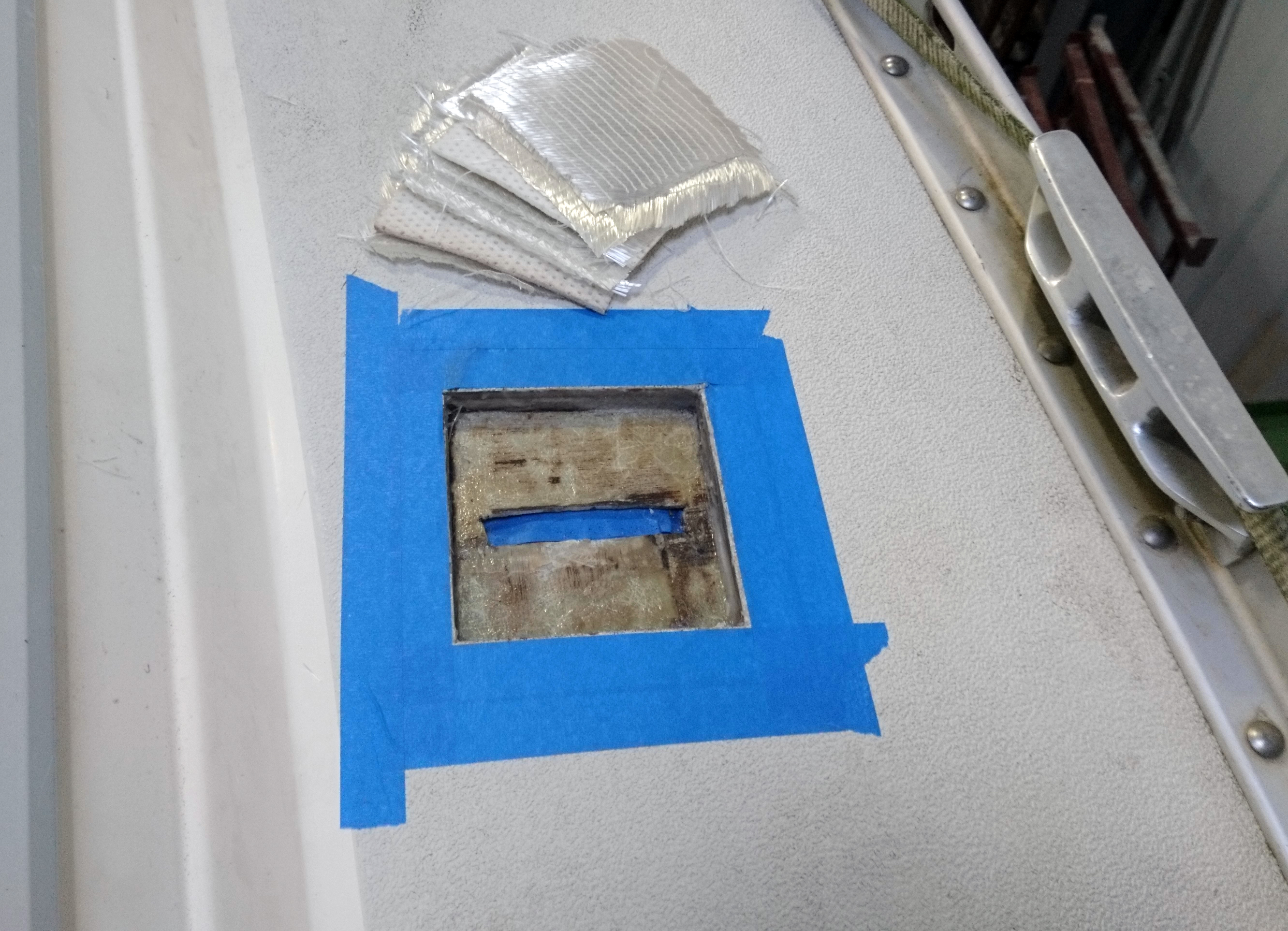
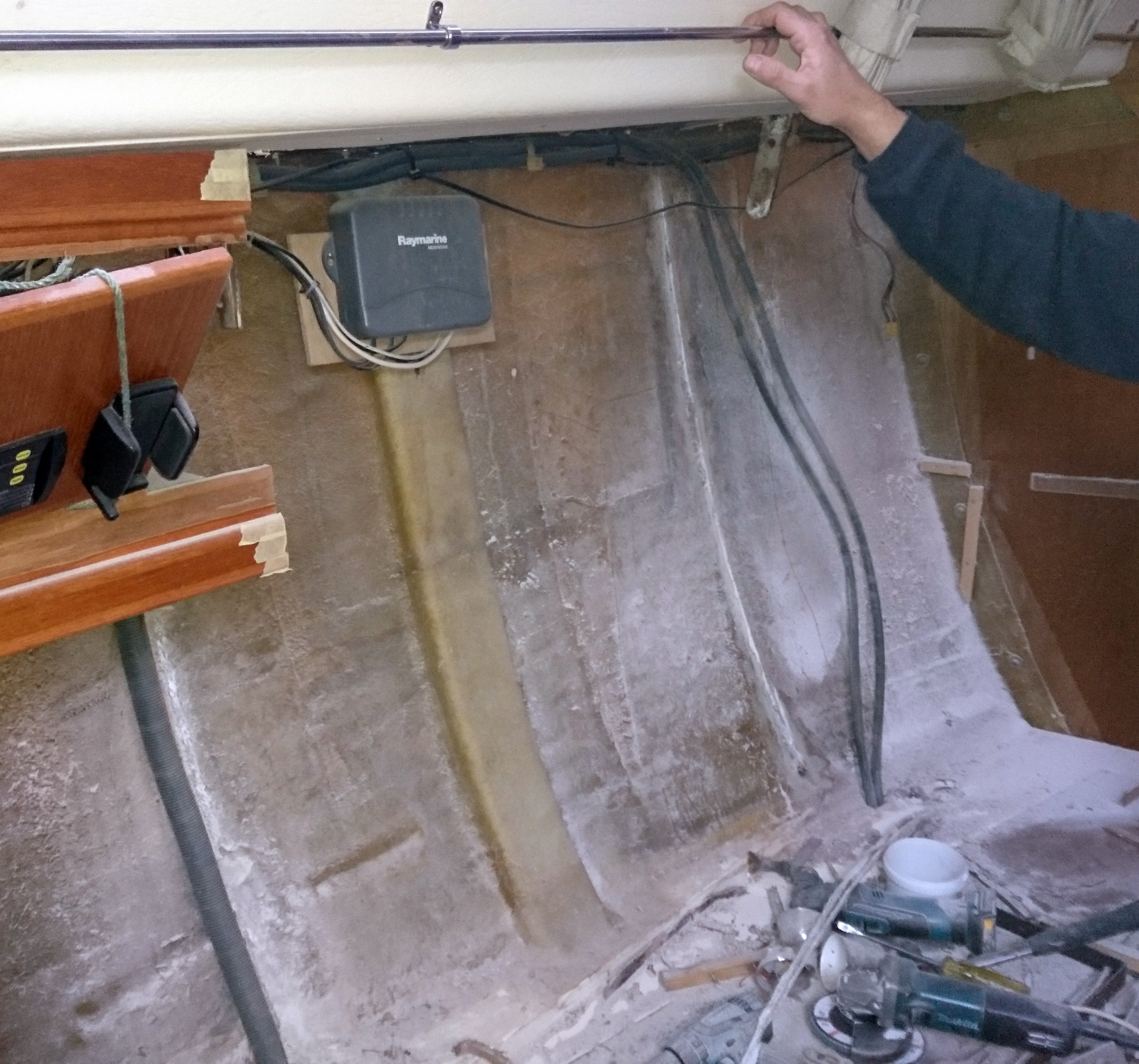
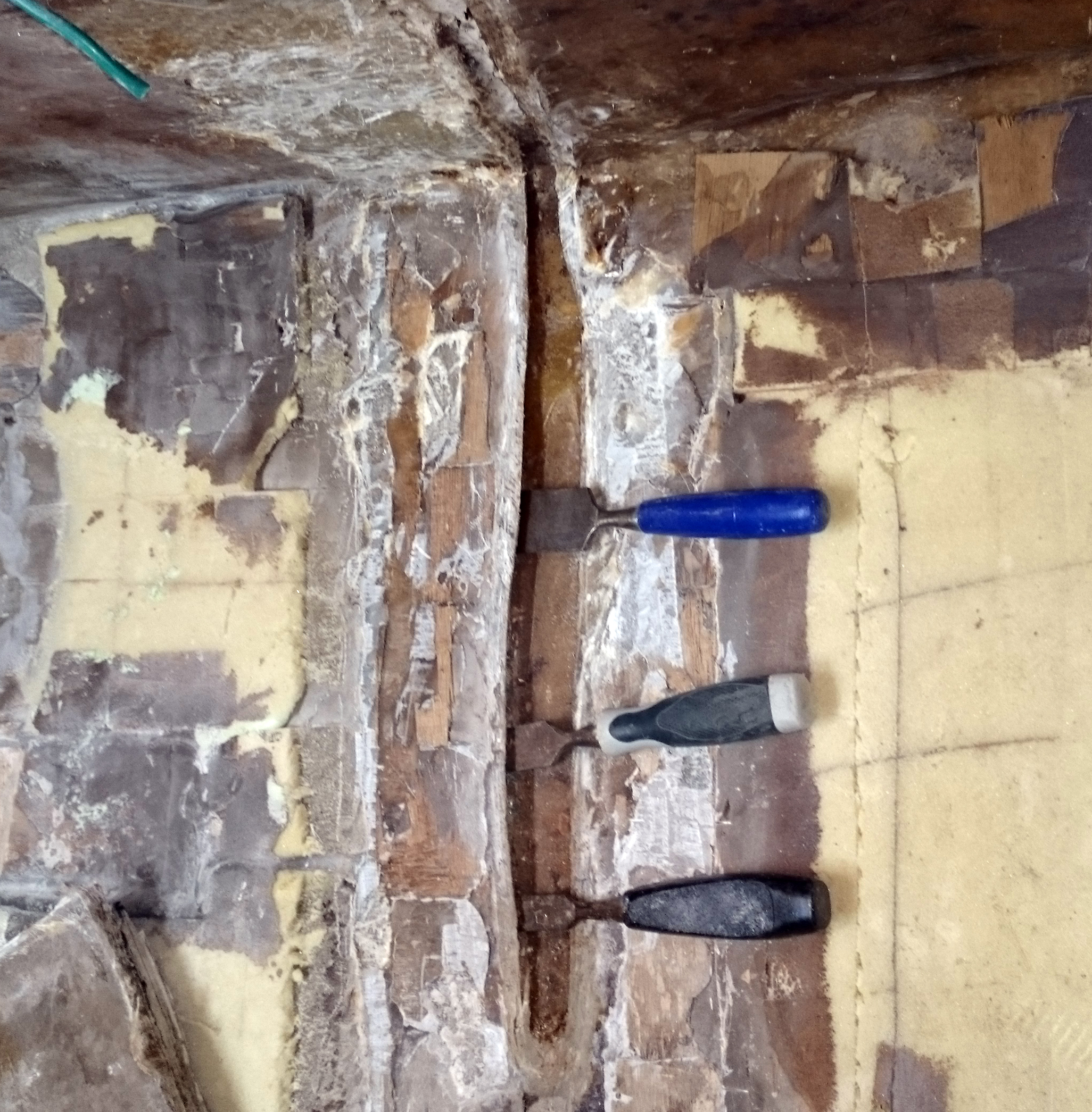
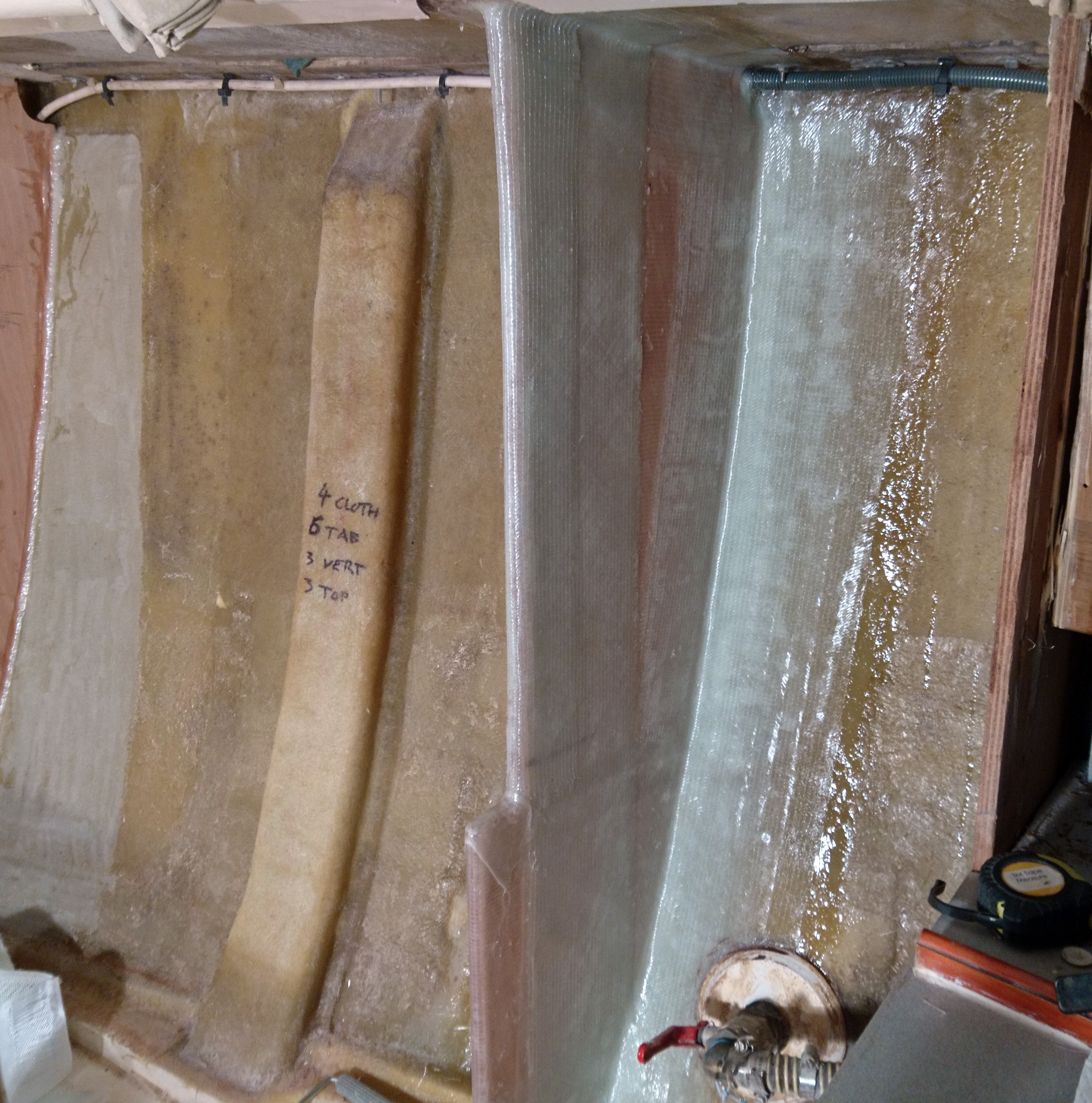
The area around the base of the post was taped up with plastic sheeting to try and contain the dust and the hull was ground back to clean glass.
A section of old supporting rib screwed to the lower section of the bulkhead was also removed as there was evidence of water damage, along with the rotten pieces of hard wood used as piers for the bridge.

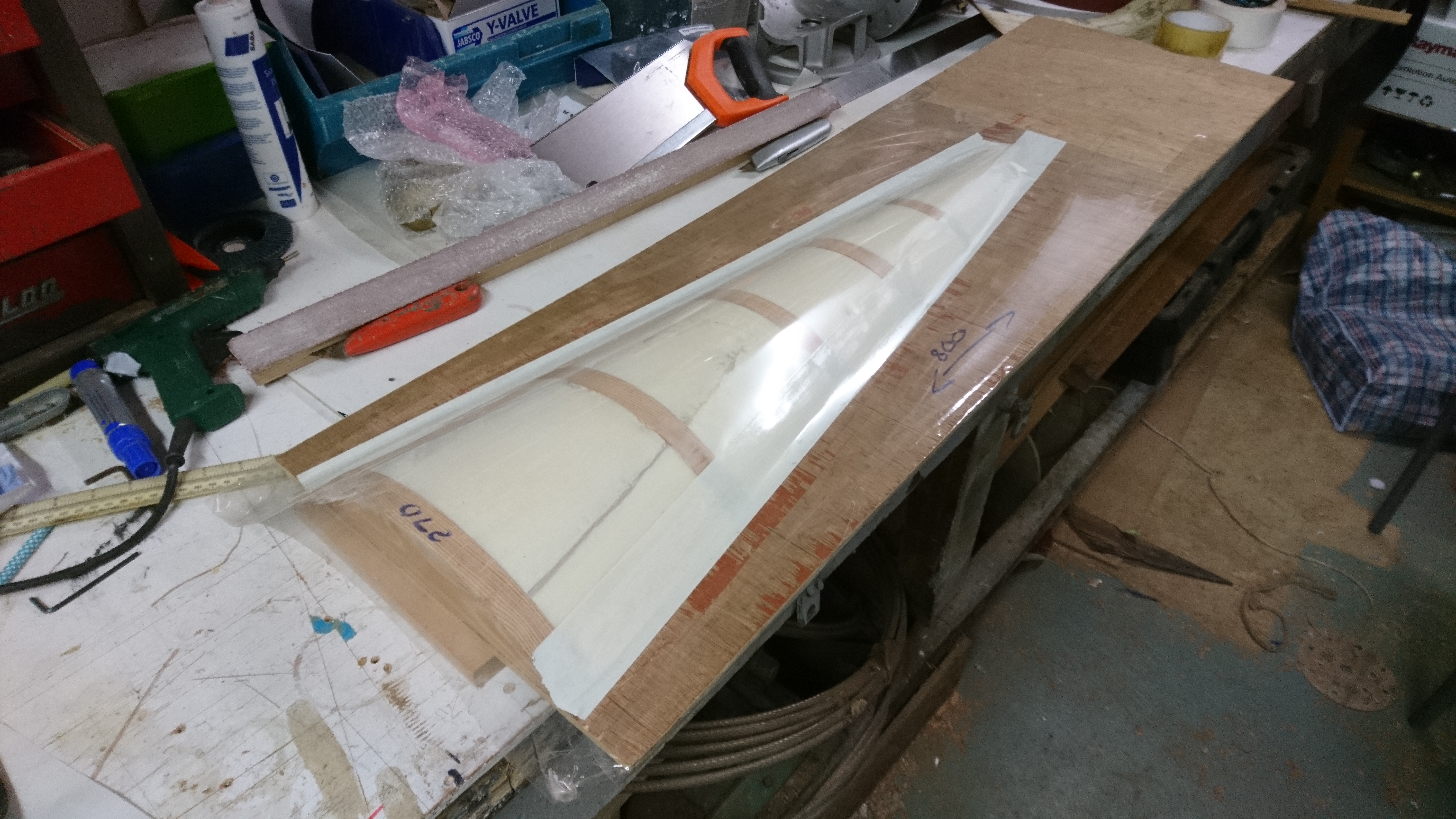
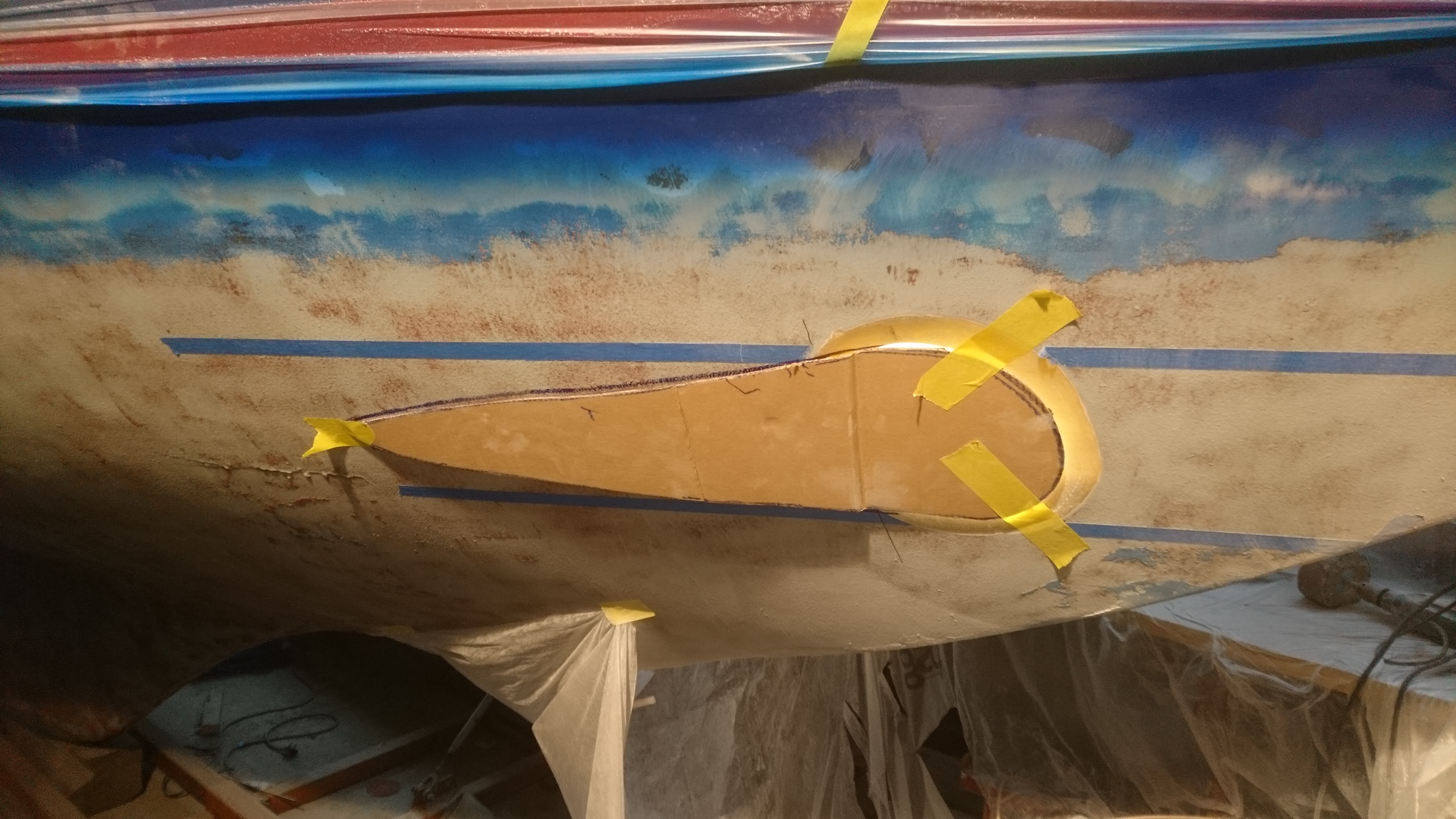
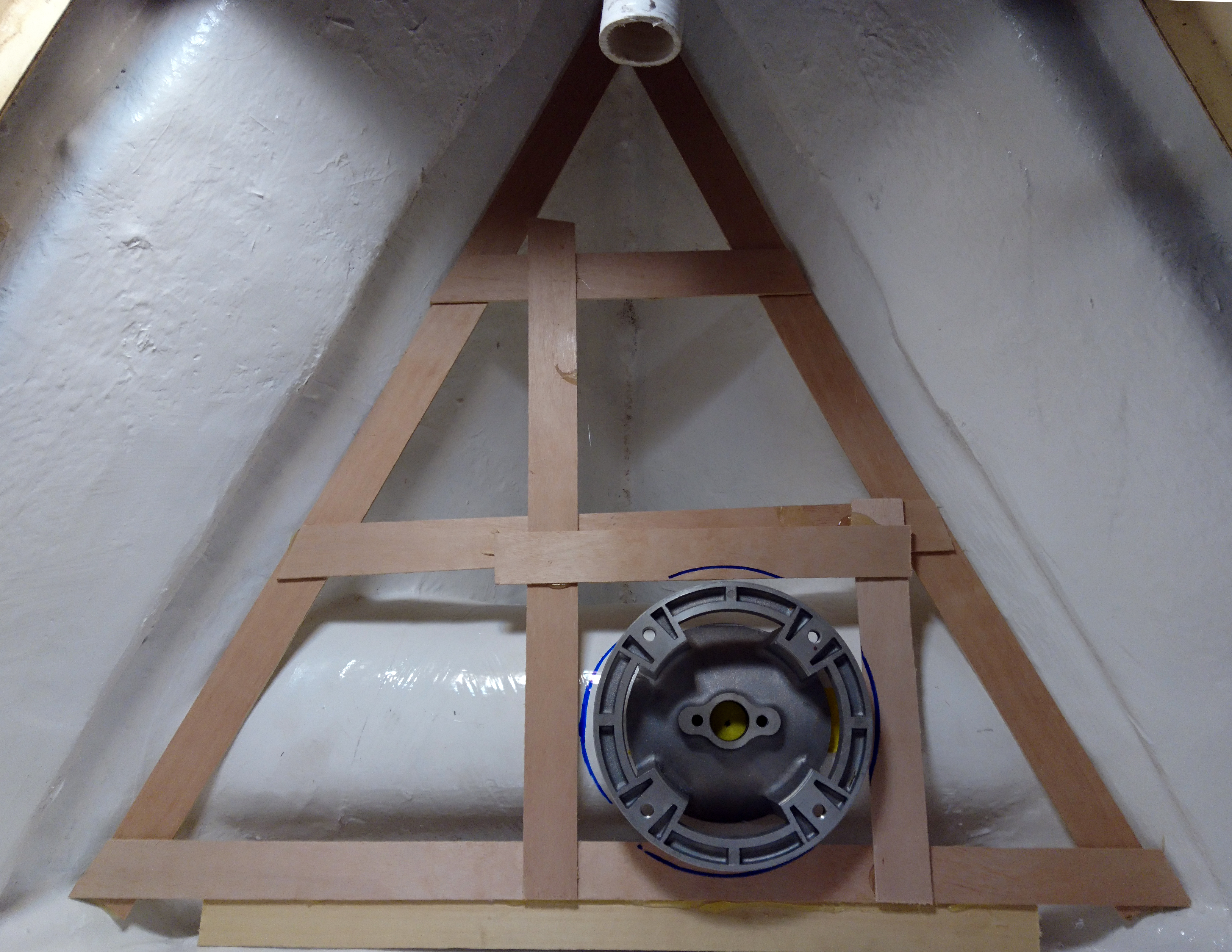
Using 2″ wide strips of scrap ply and a glue gun, a template for the new supporting rib was stuck together.
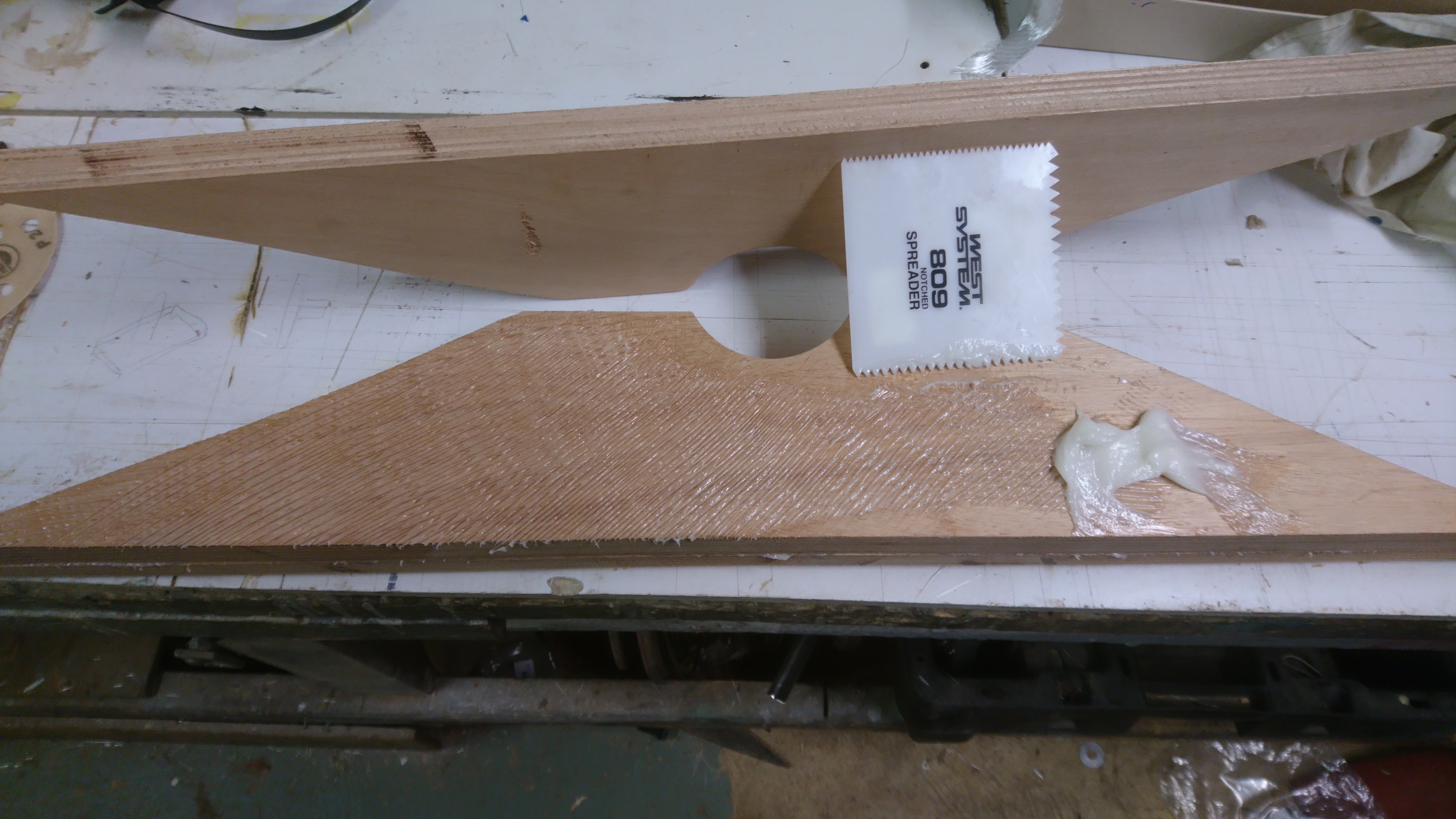
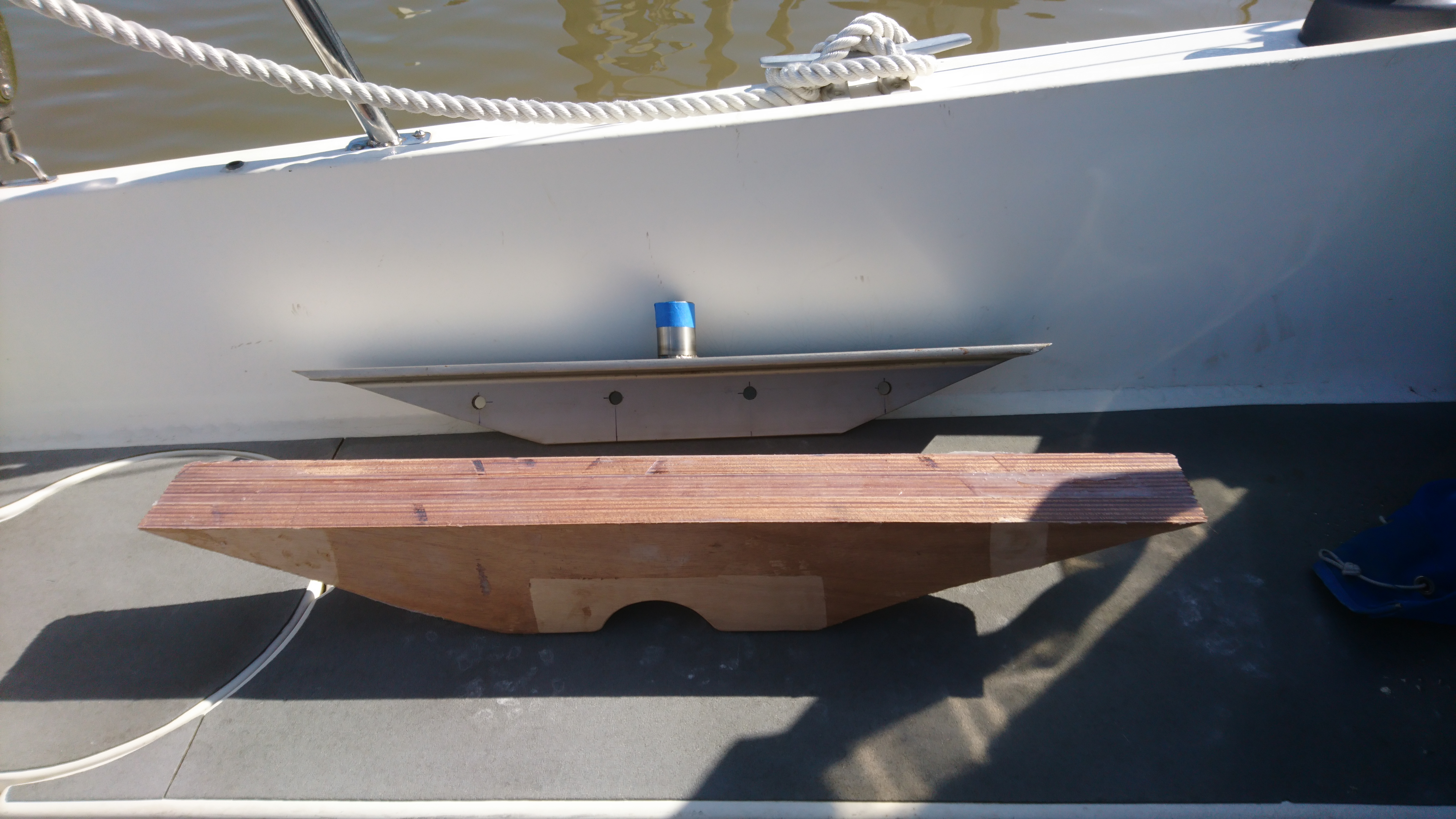
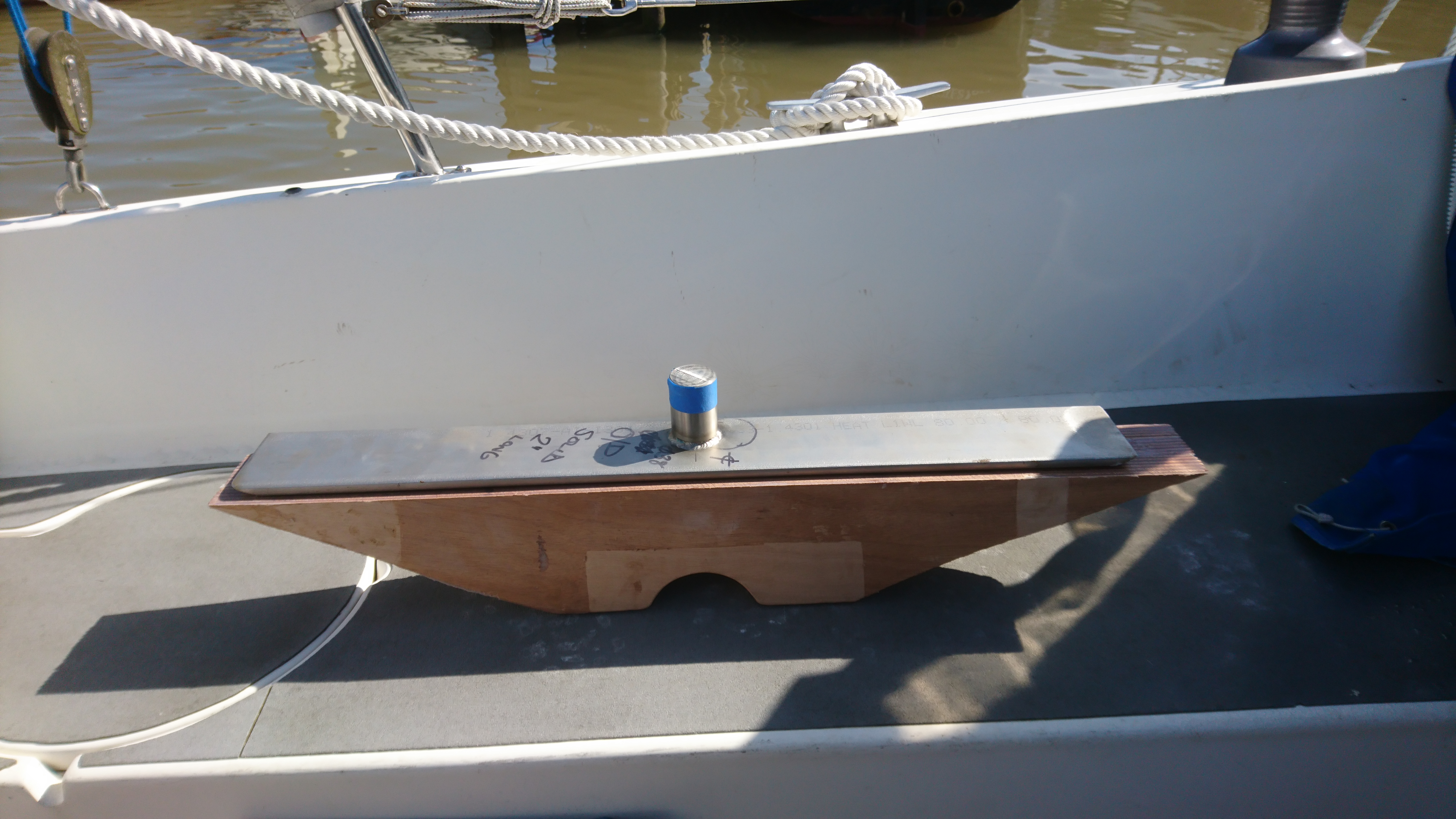
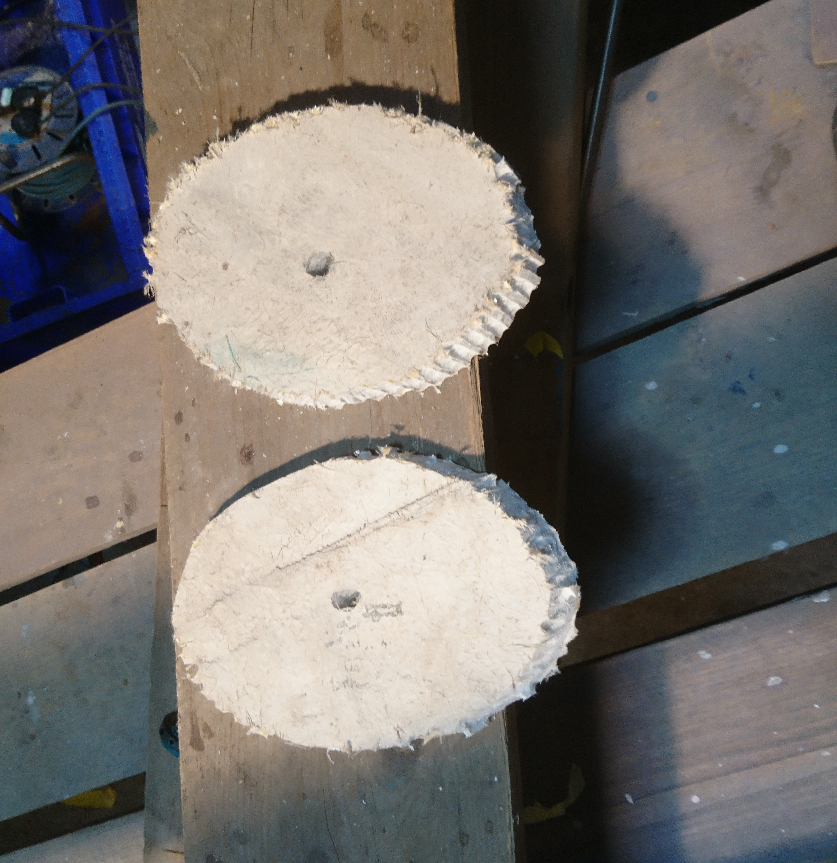
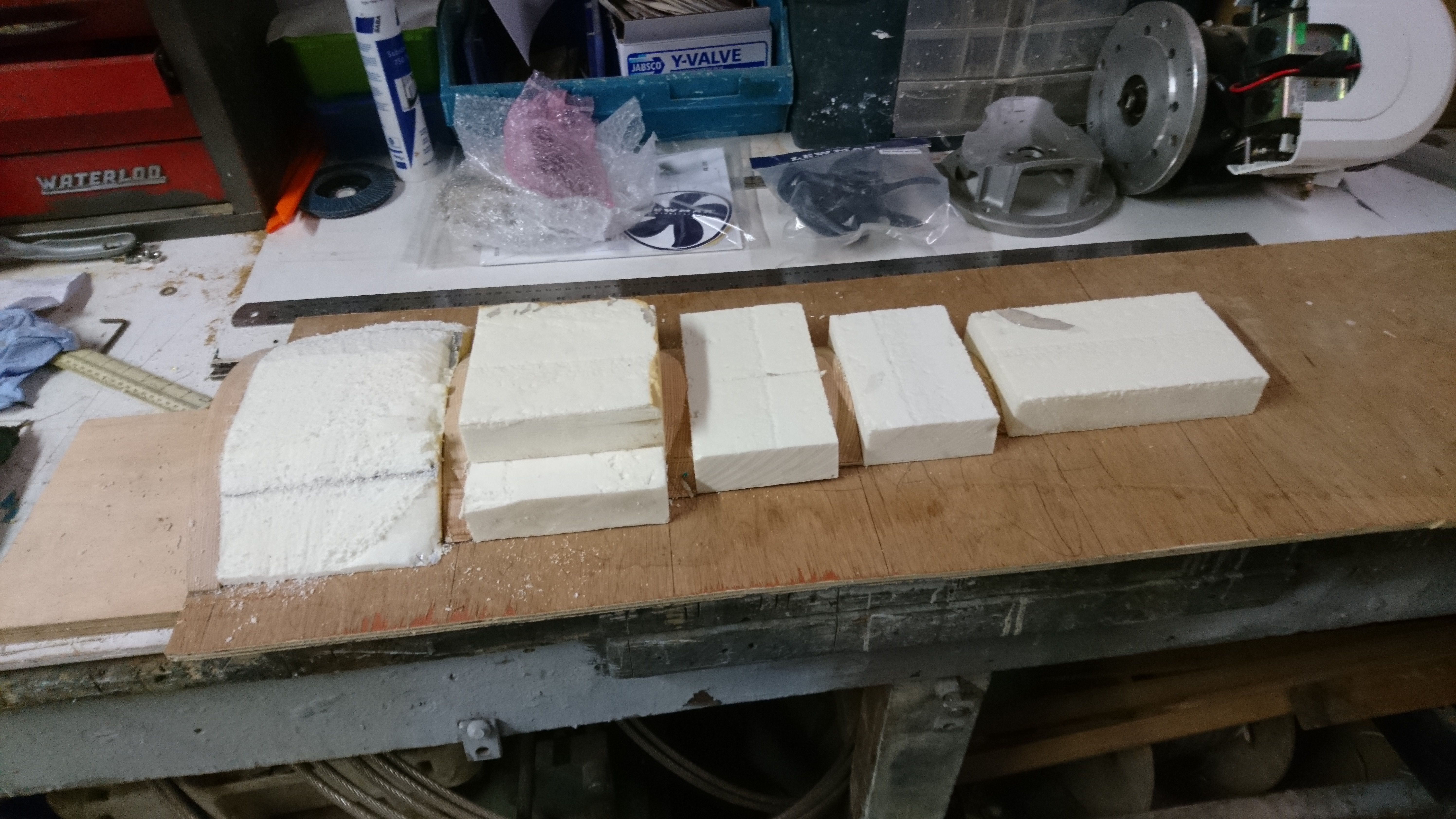
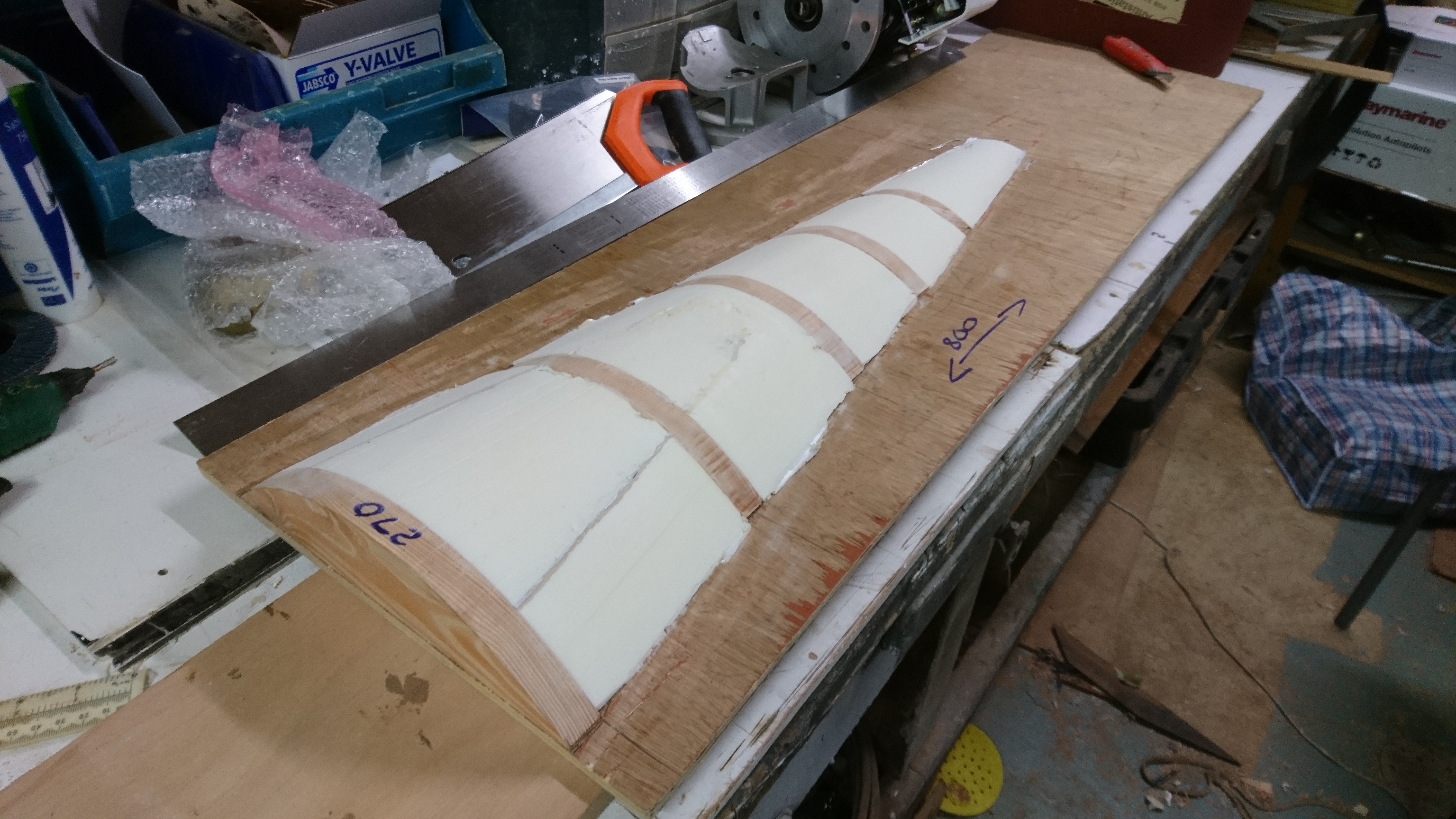
I decided to build the new rib out of 4 layers of 25mm thick marine plywood, laminated together using thickened West epoxy.
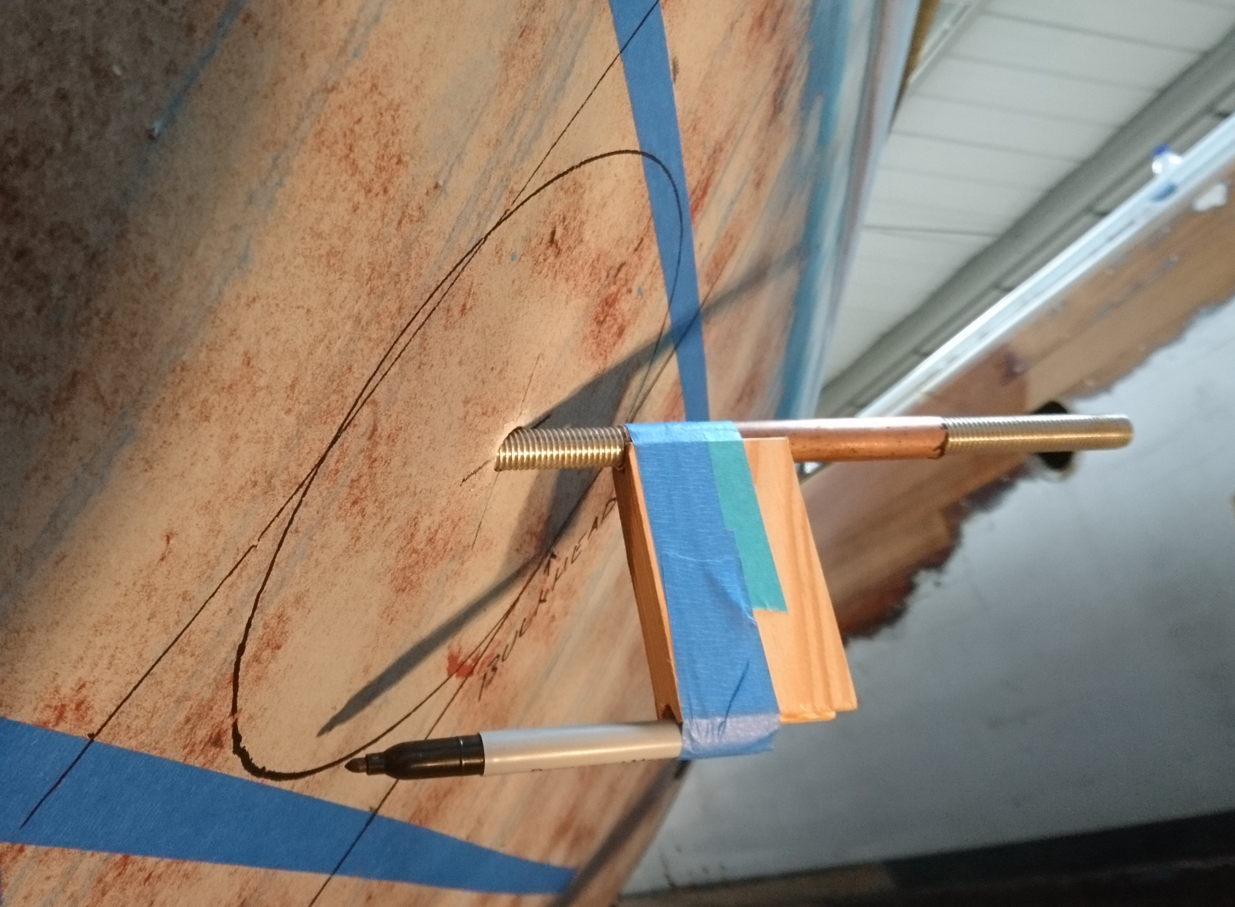
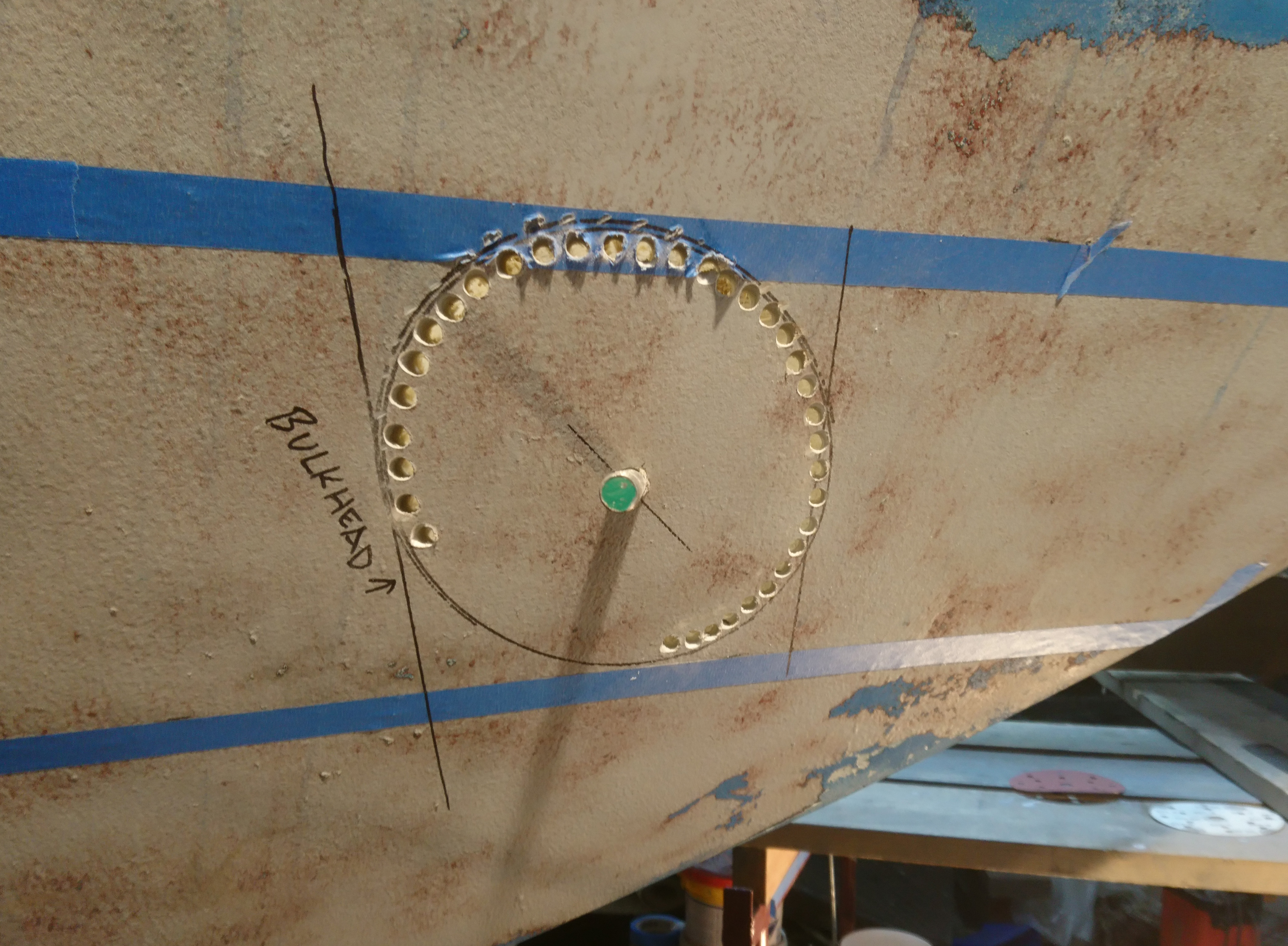
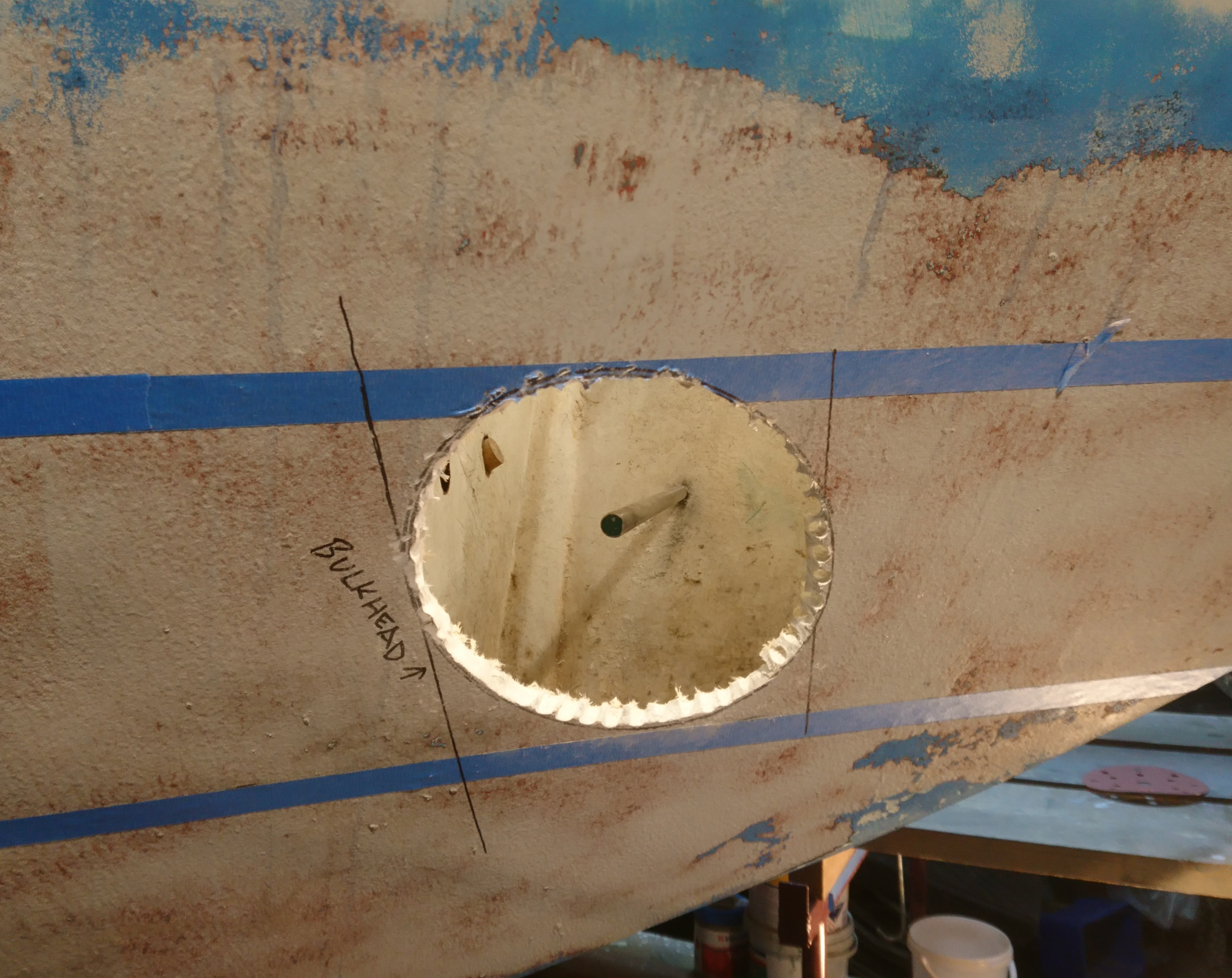
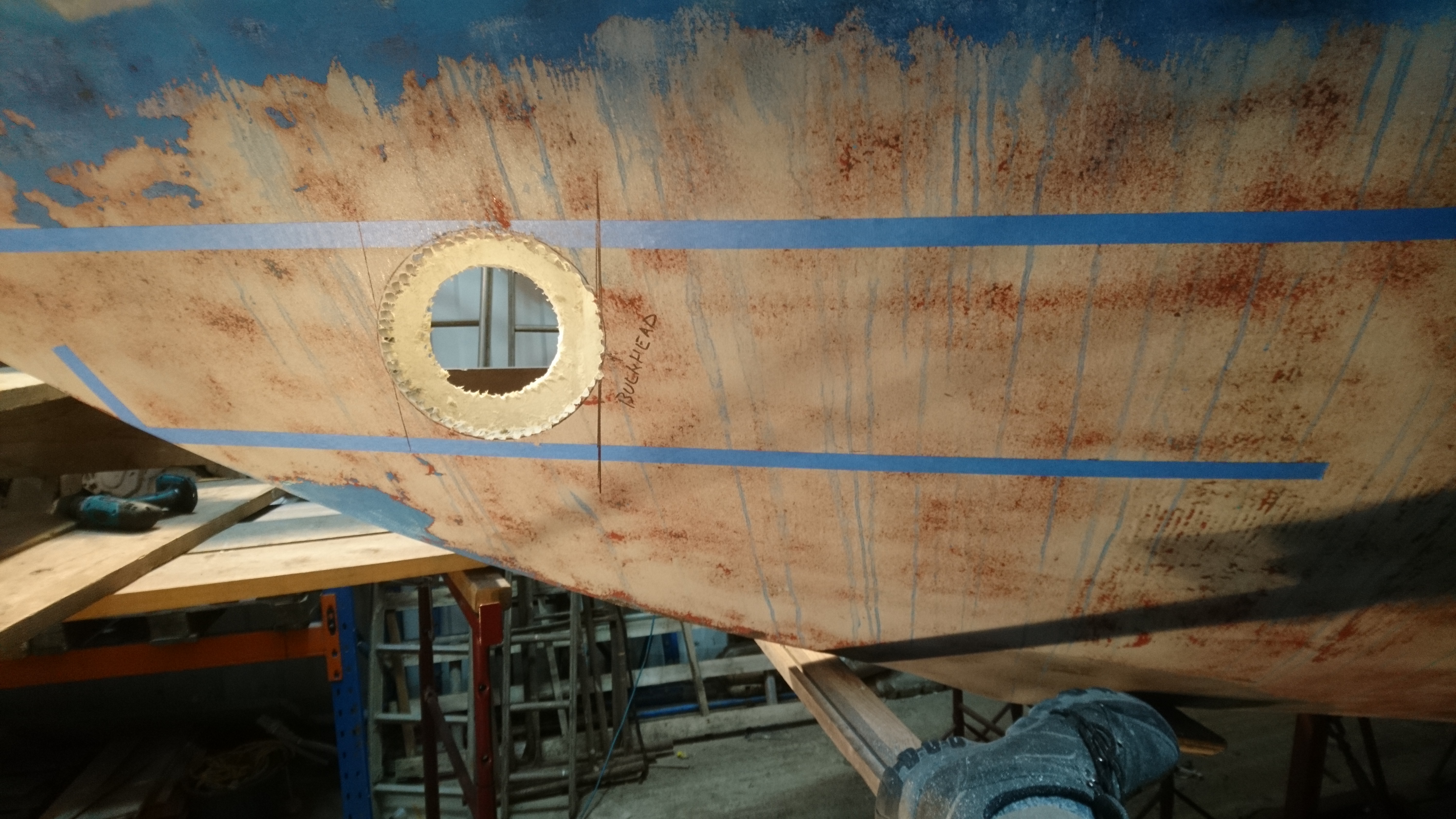
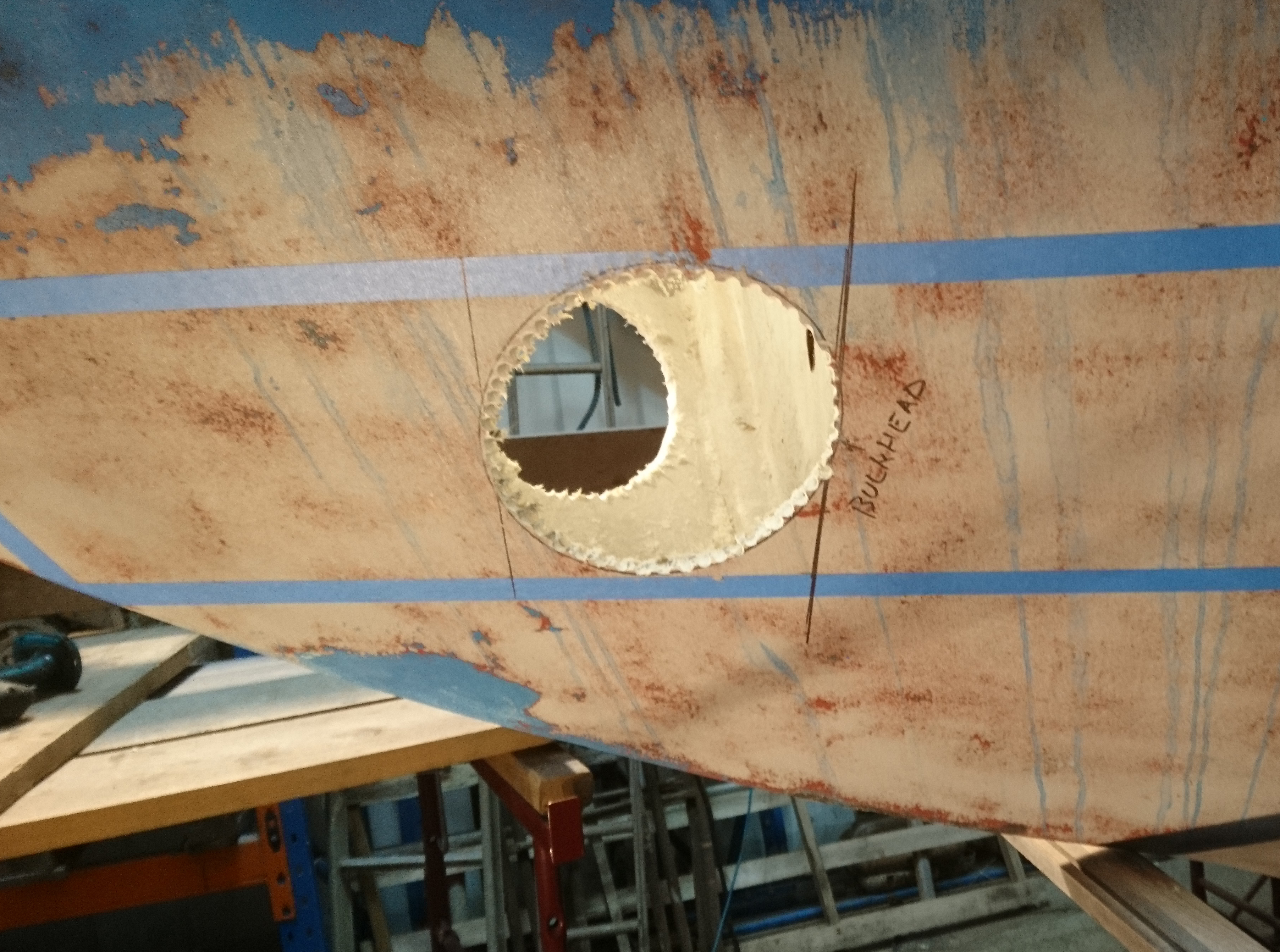
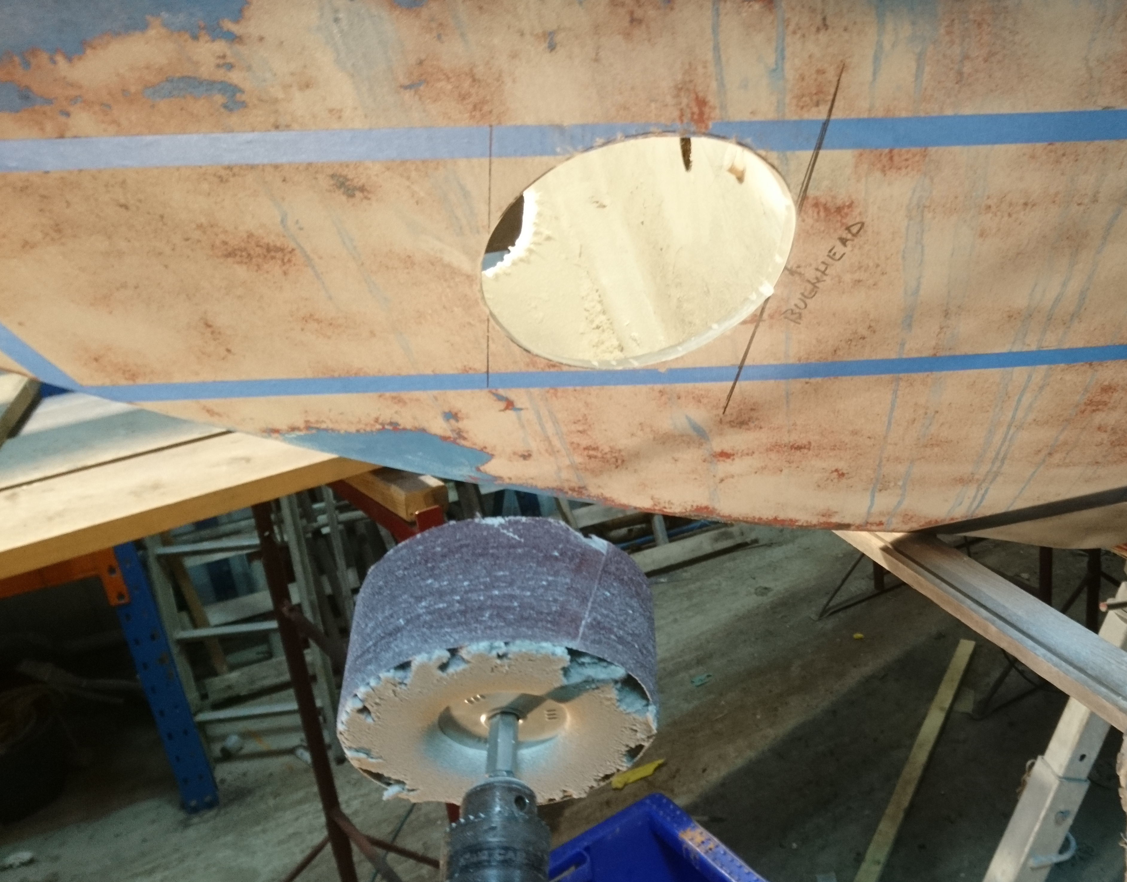
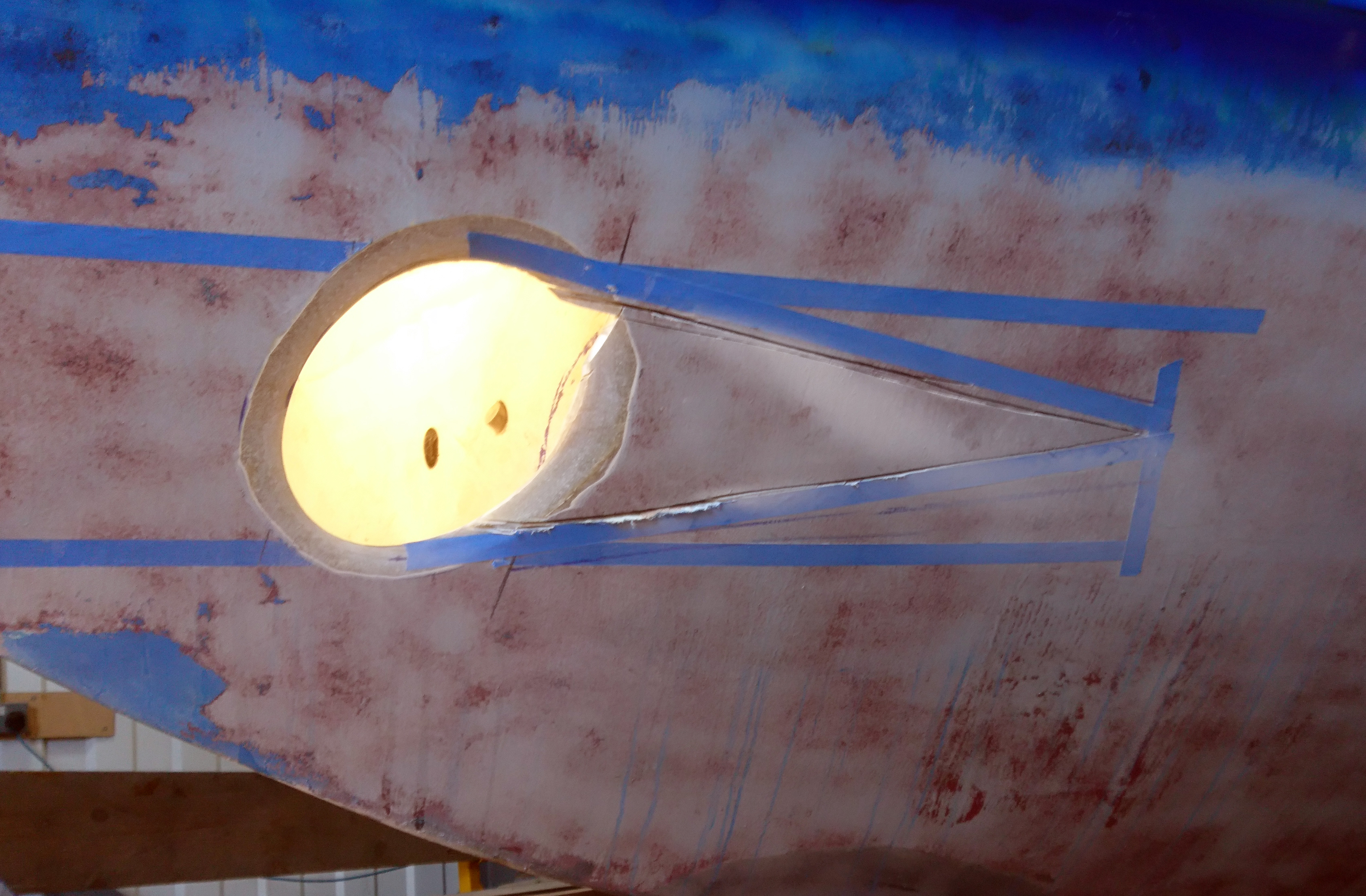
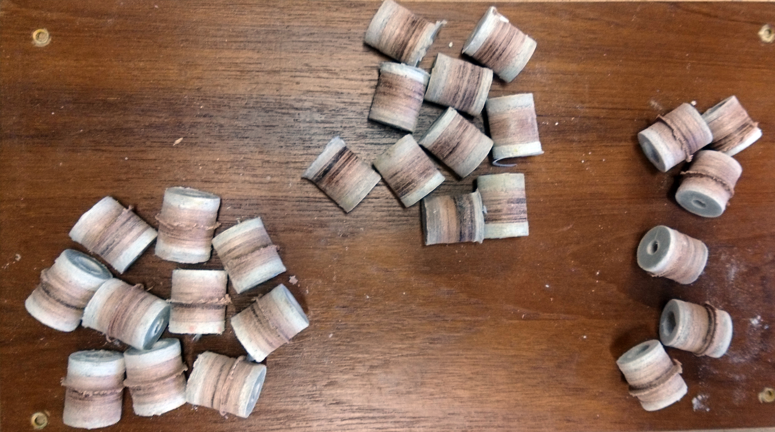
After a test dry fit a section was removed in the center with a large hole cutter to allow access to the keel-bolt head.

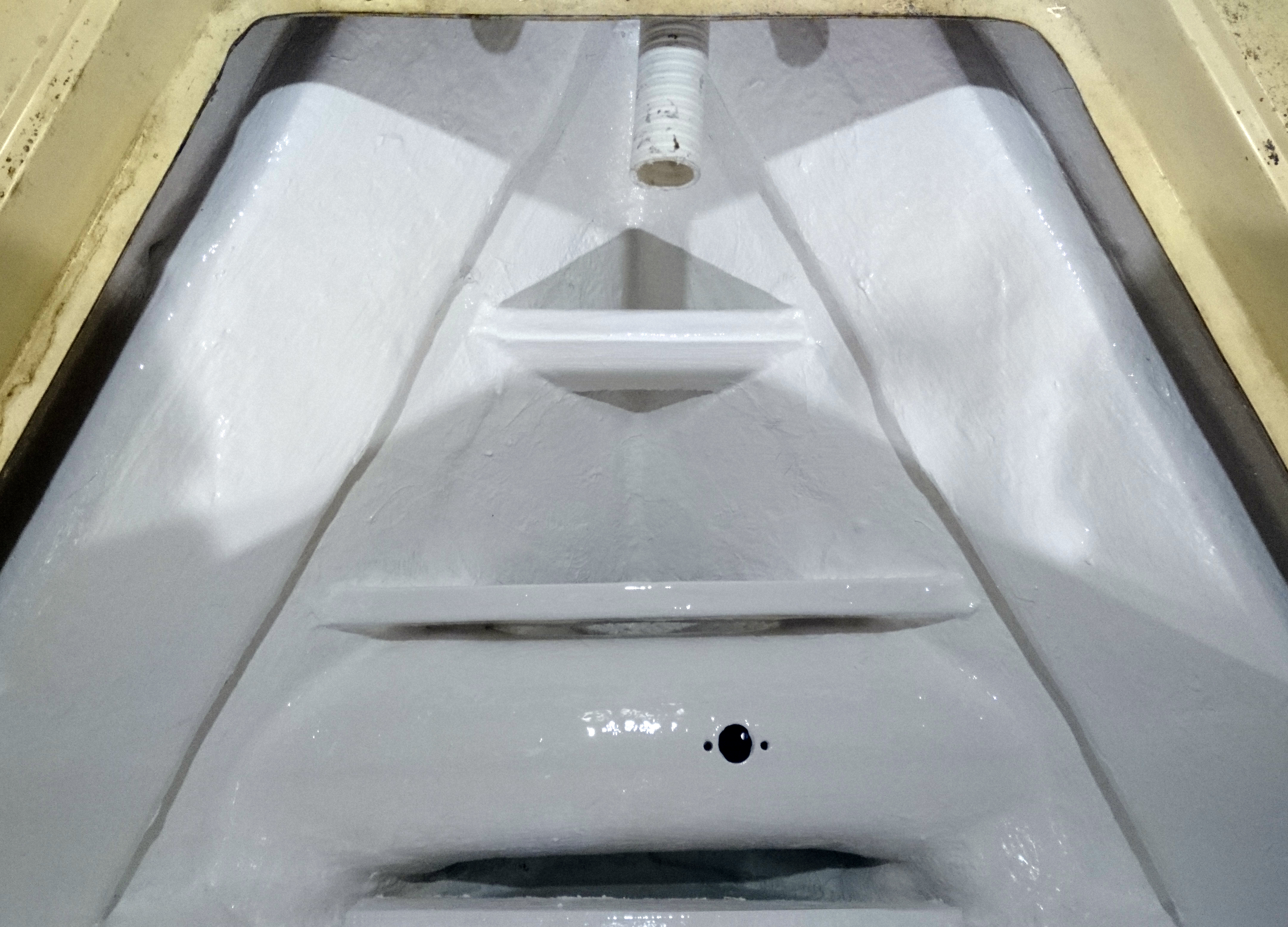
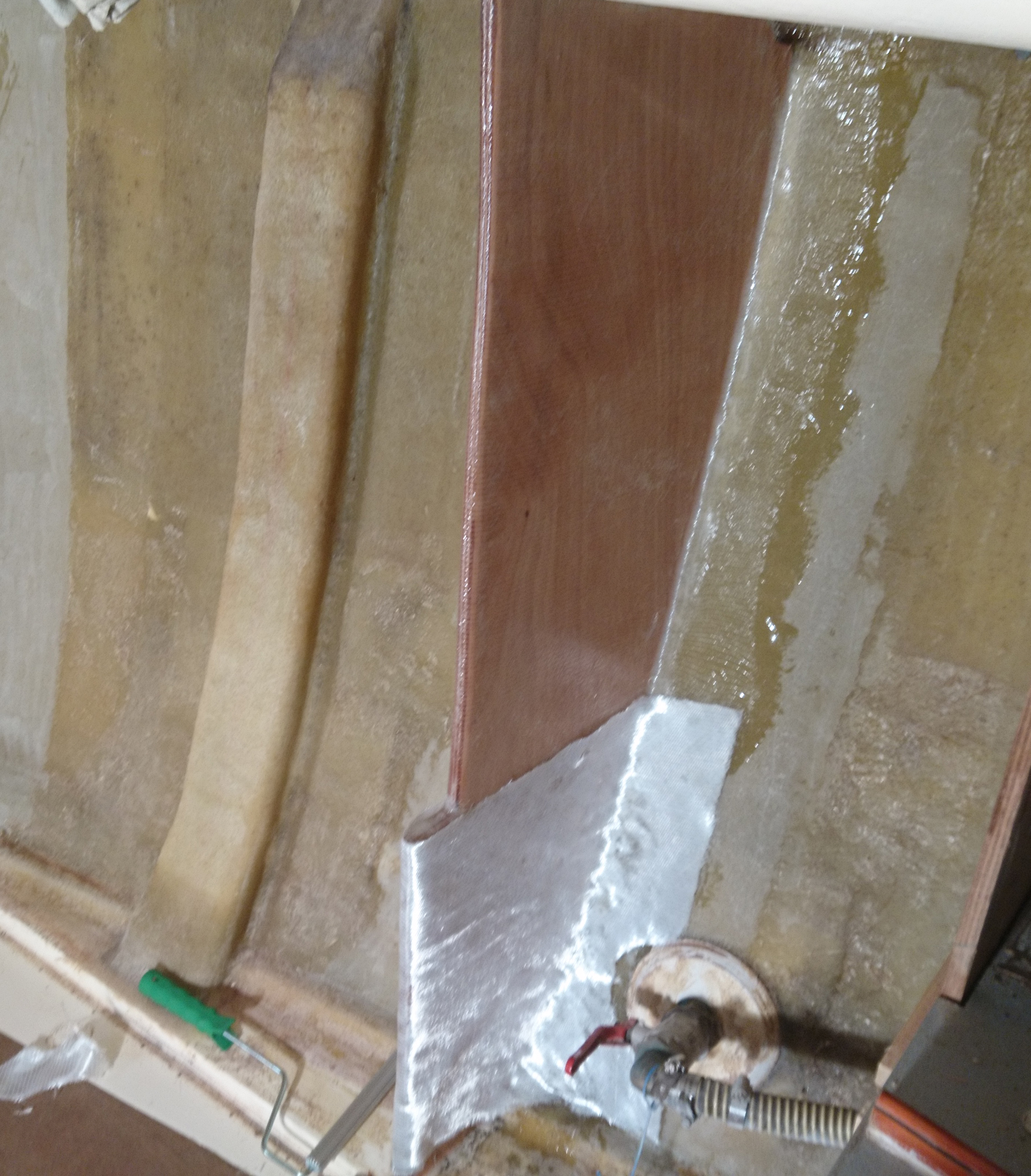
To ensure the loads on the support rib are transferred to the hull effectively its important achieve a close match between the rib landing surface and the hull.
It takes a number of test fits to get a perfect fit against the hull as typically the hull shape differs slightly from one side to the other, a fact that in my experience is normal though it does tend to surprise owners when you point out that their boat is not symmetrical.

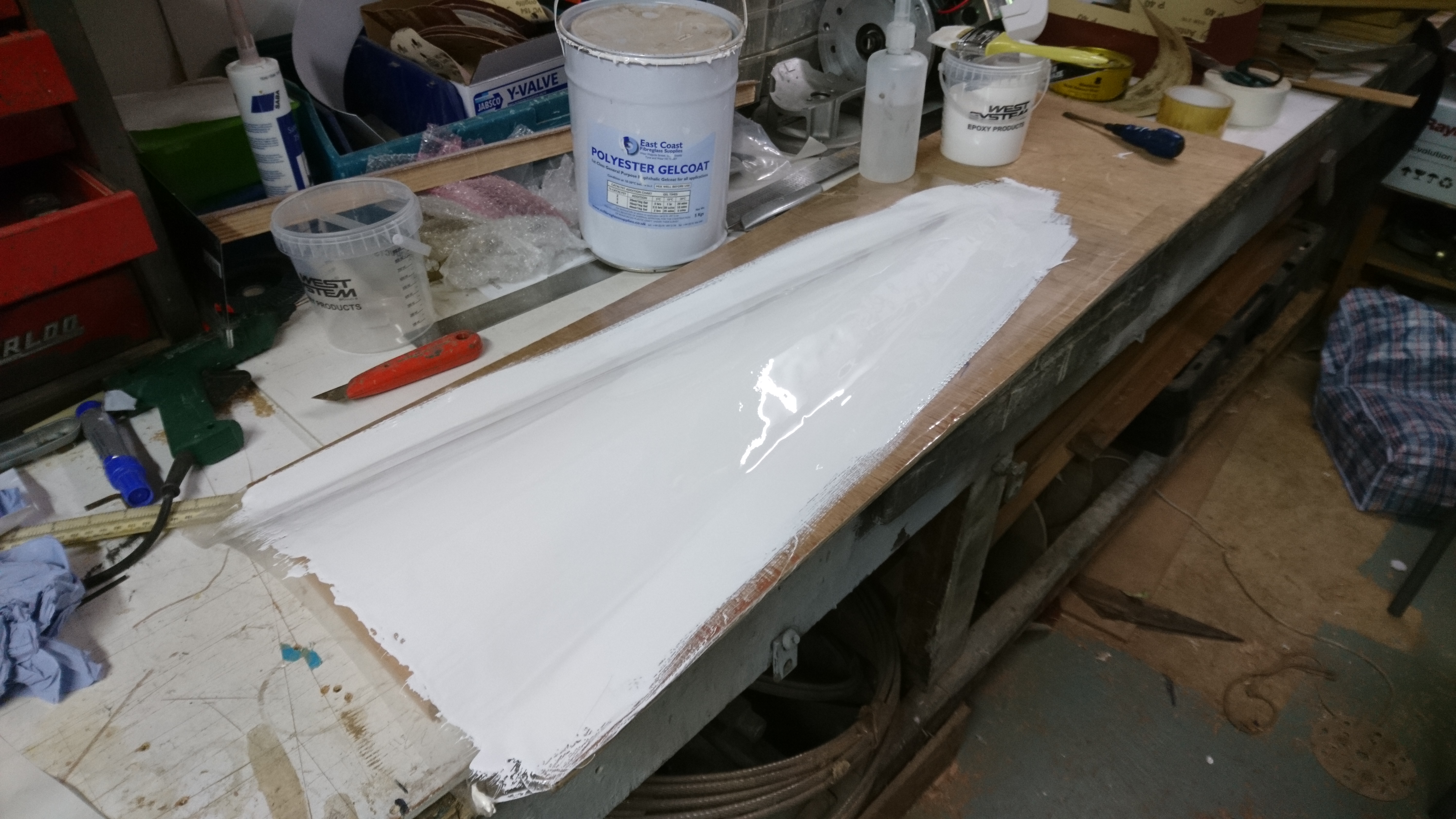
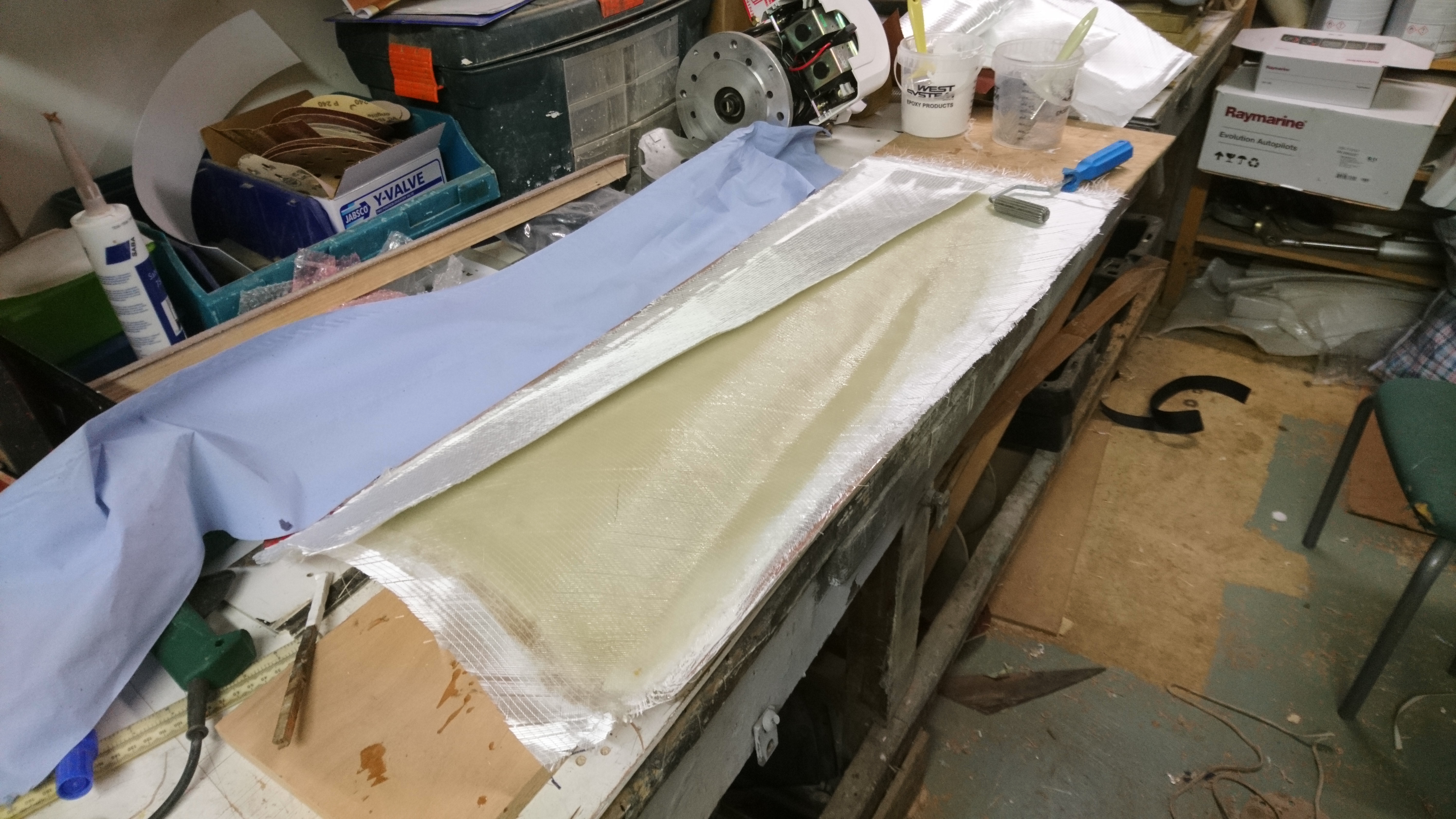
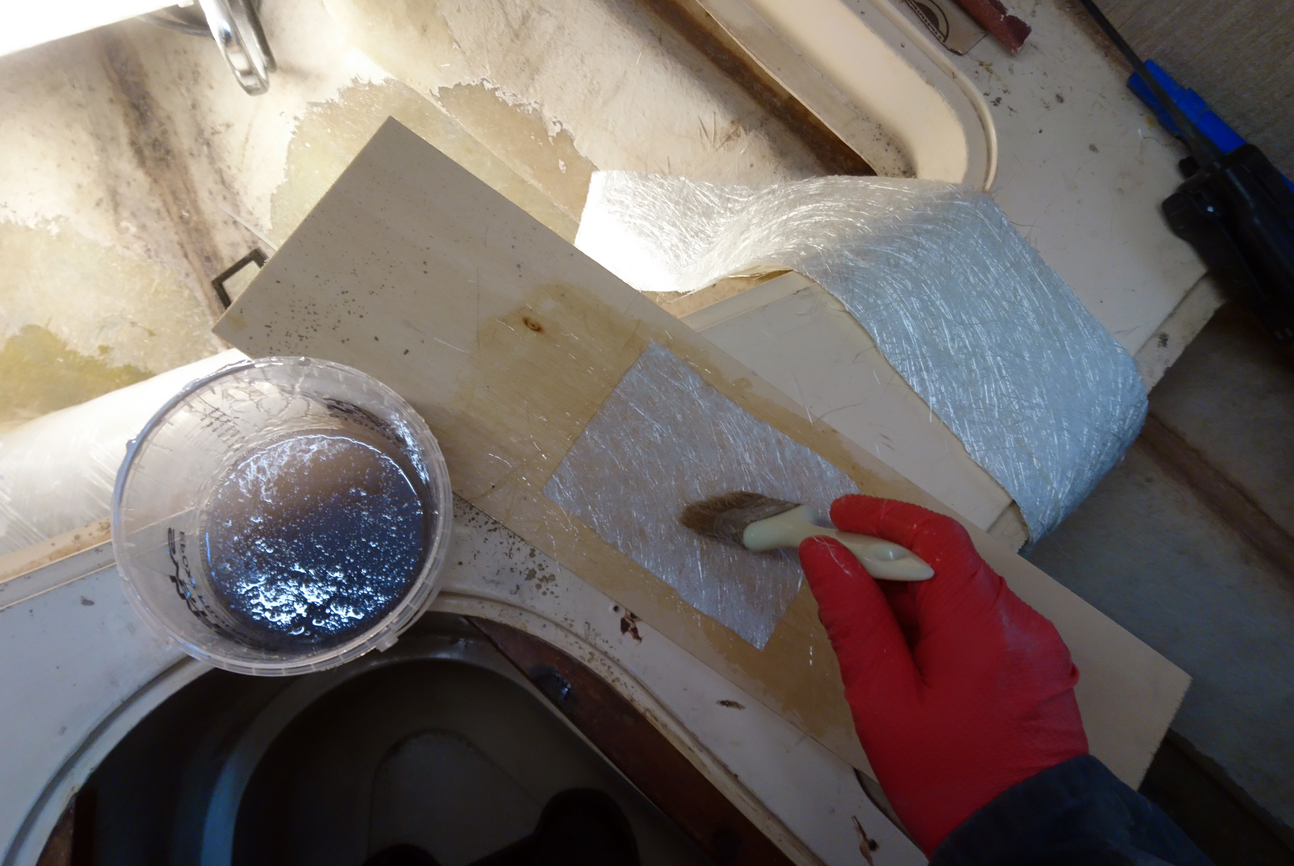
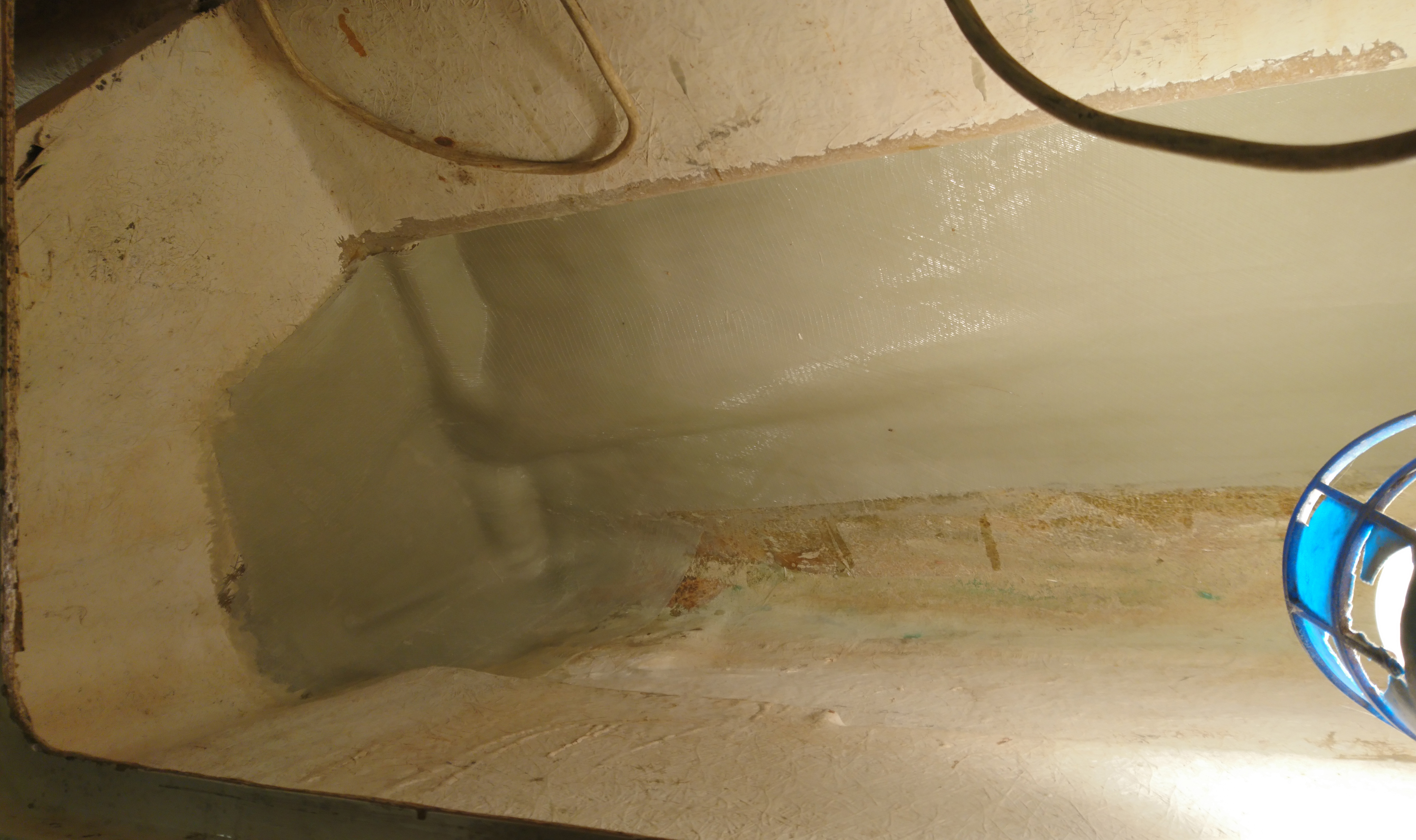
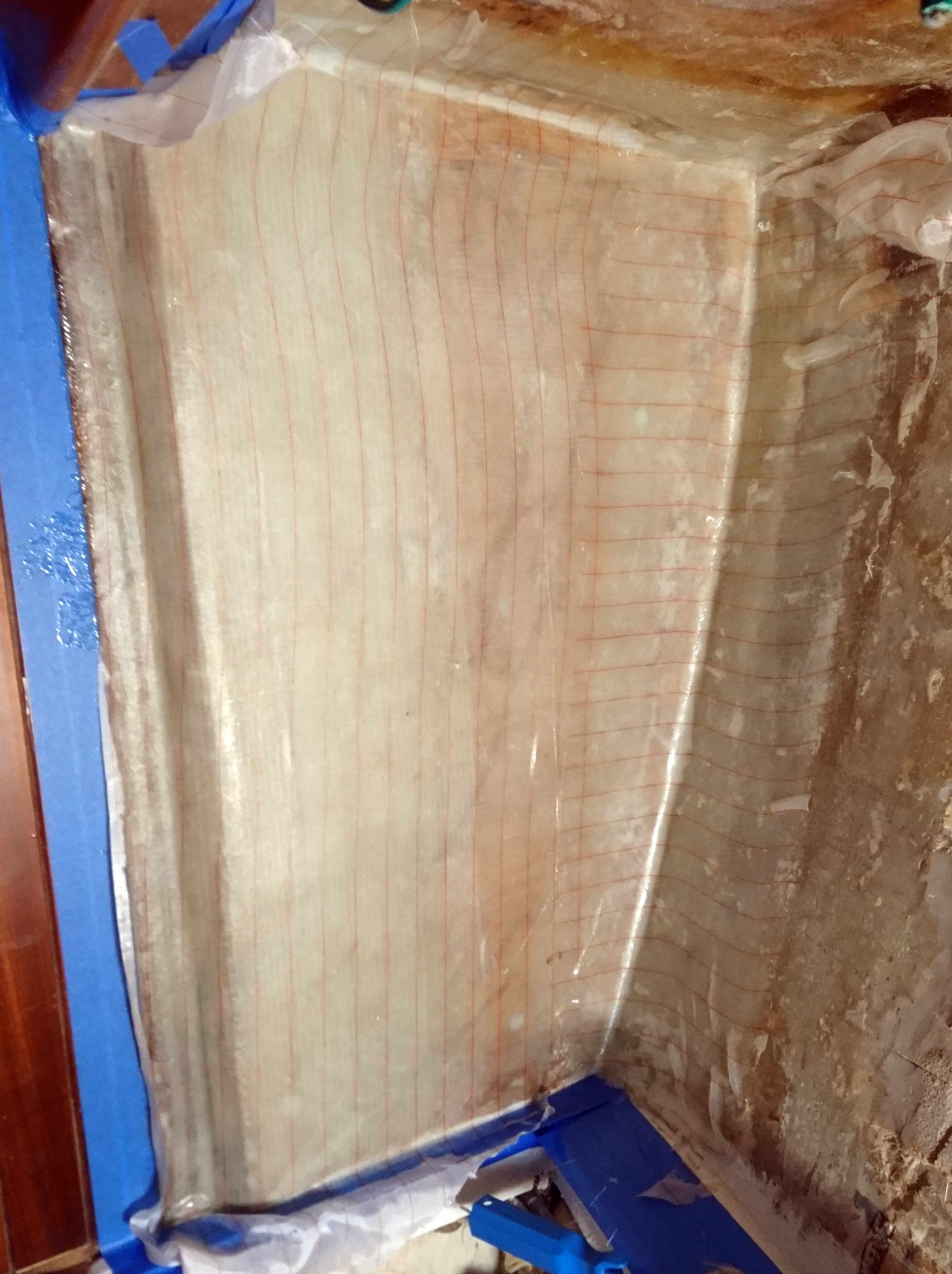
Once completed the support rib was then sealed with glass cloth and epoxy.
The top of the support angle was also going to be the bearer for the floor so the support rib height had to allow for the 10mm thickness of the angle and the thickened epoxy that would bond it to the hull.
The last dry fit therefore included laying the support rib on a cardboard gasket to match the required thickness of epoxy in the joint and then the bolt holes were drilled through.
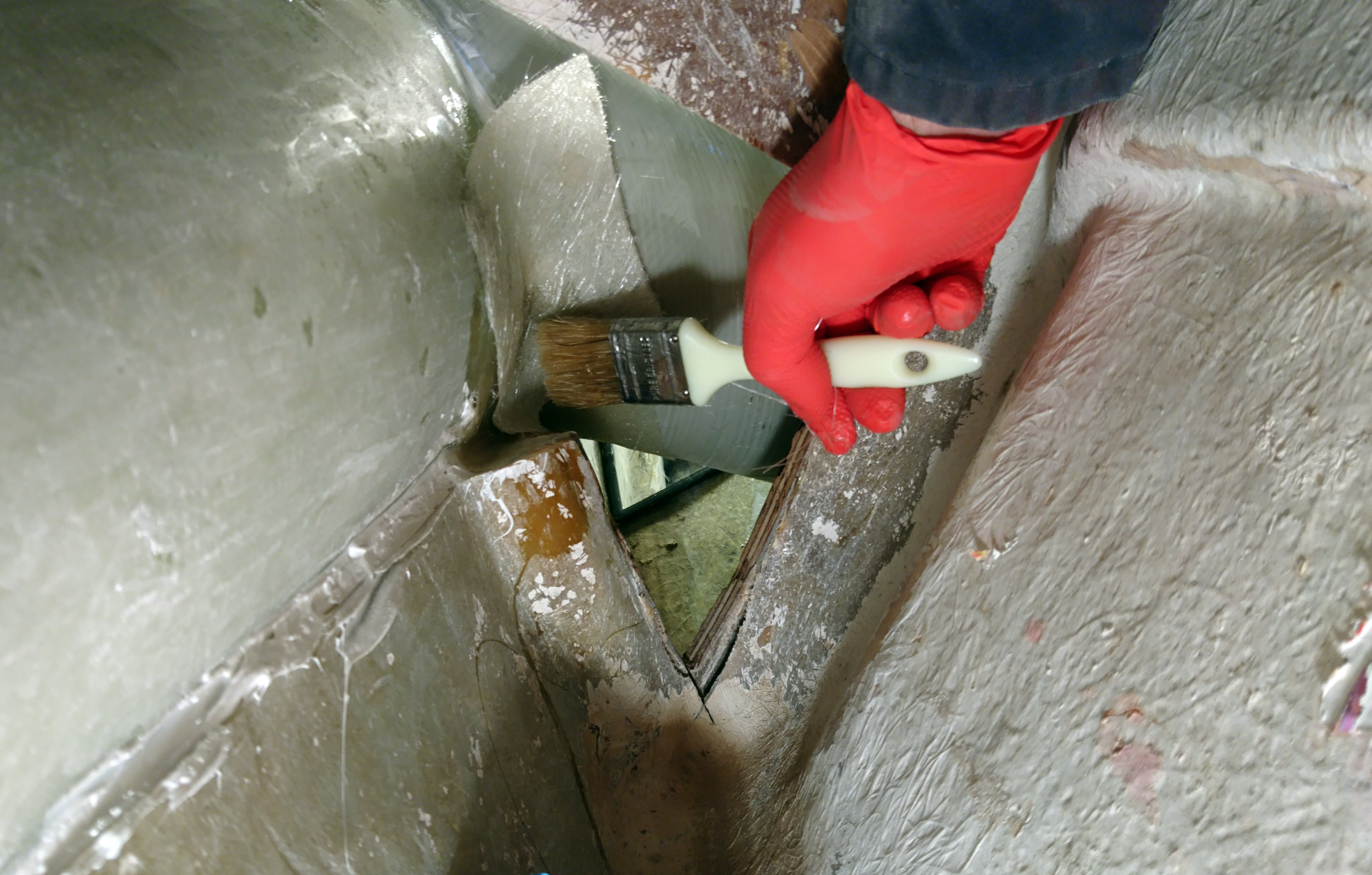
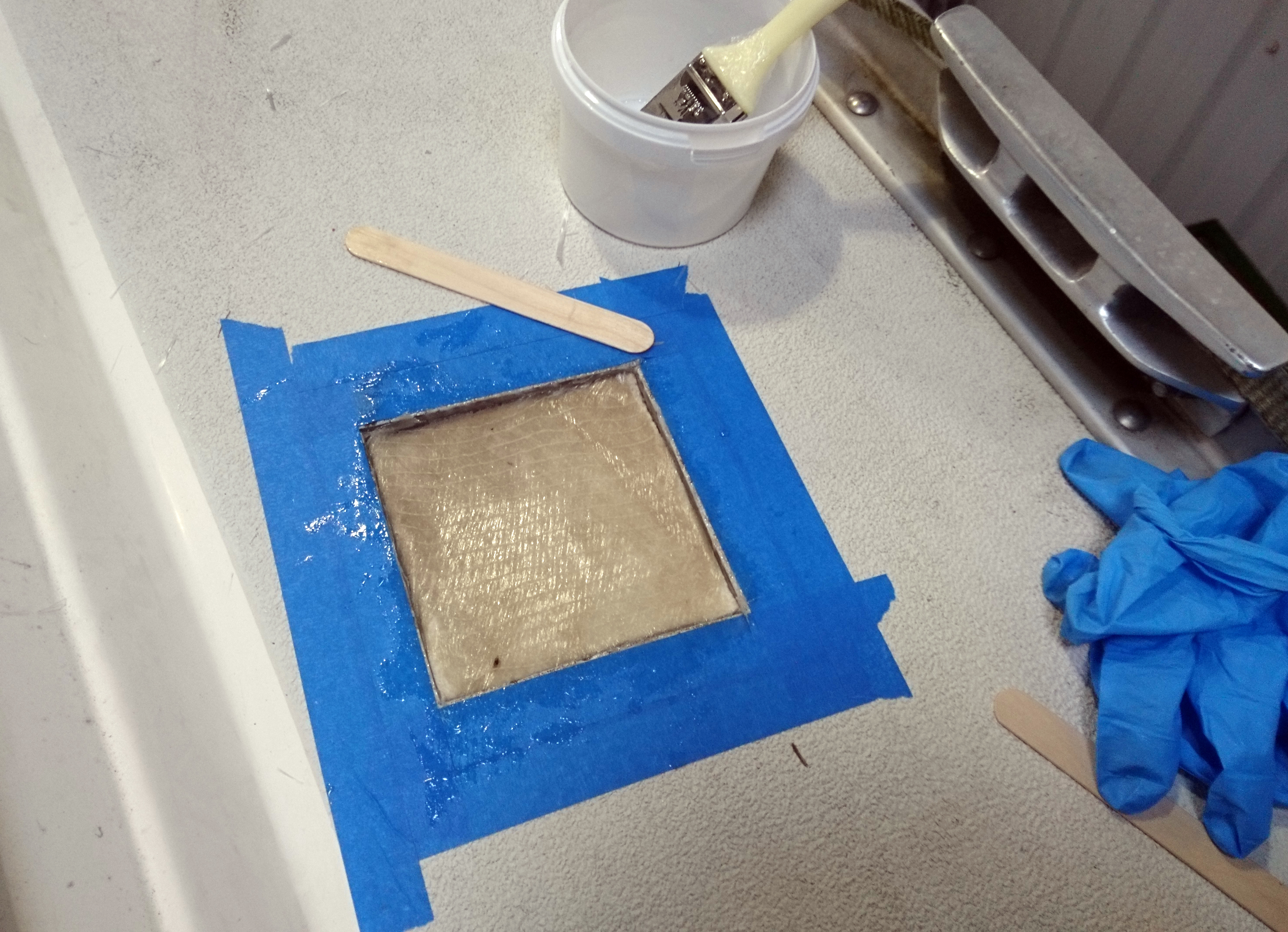
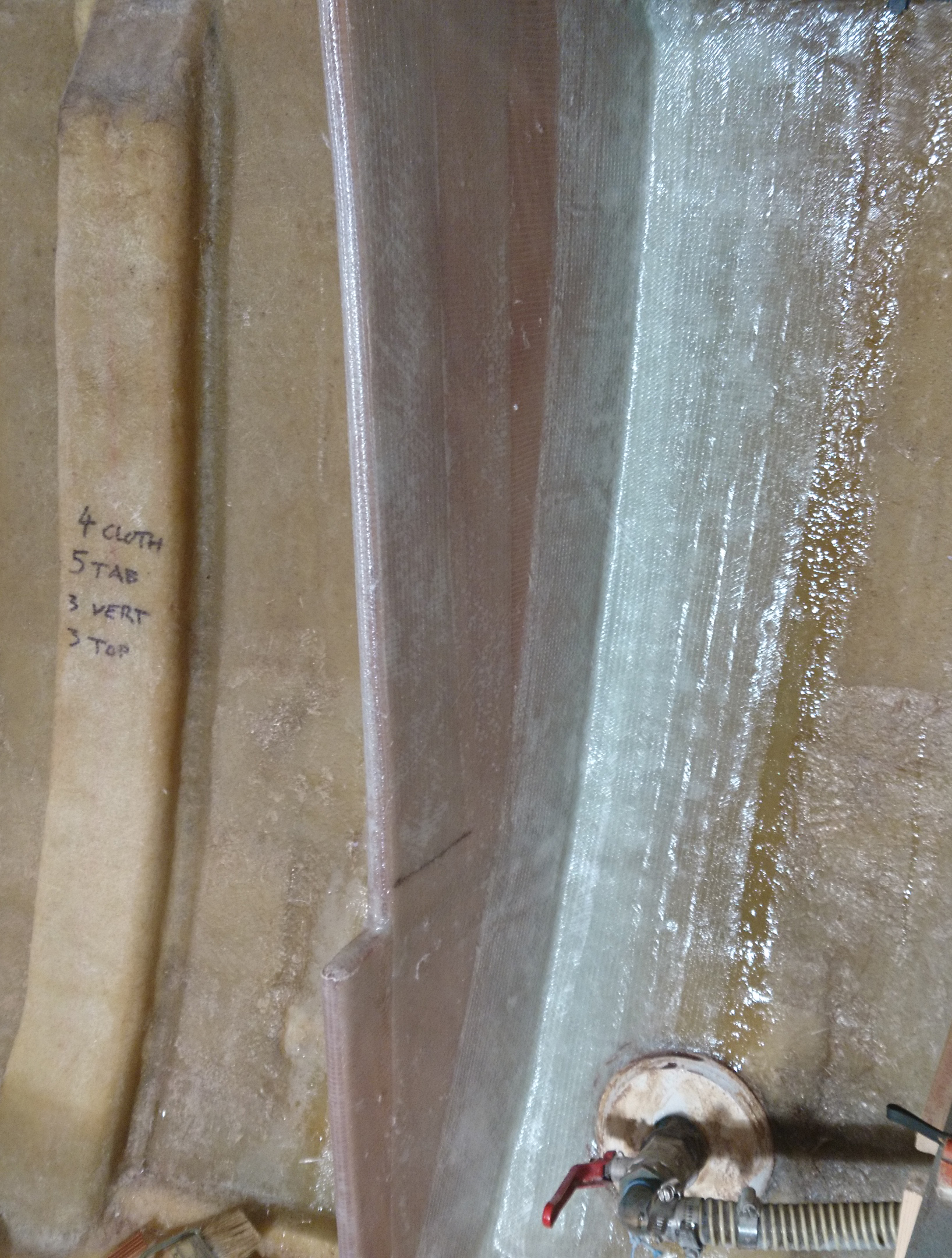
As usual I use a two step bonding process.
The first is to wet out the bonding surfaces with neat resin/hardener to ensure you don’t get any dry patches or voids.
The second is to then add thickened epoxy to one surface before pressing the components together.
Make sure you don’t press too much as all you will achieve is weakening the bond by forcing the epoxy out of the joint.
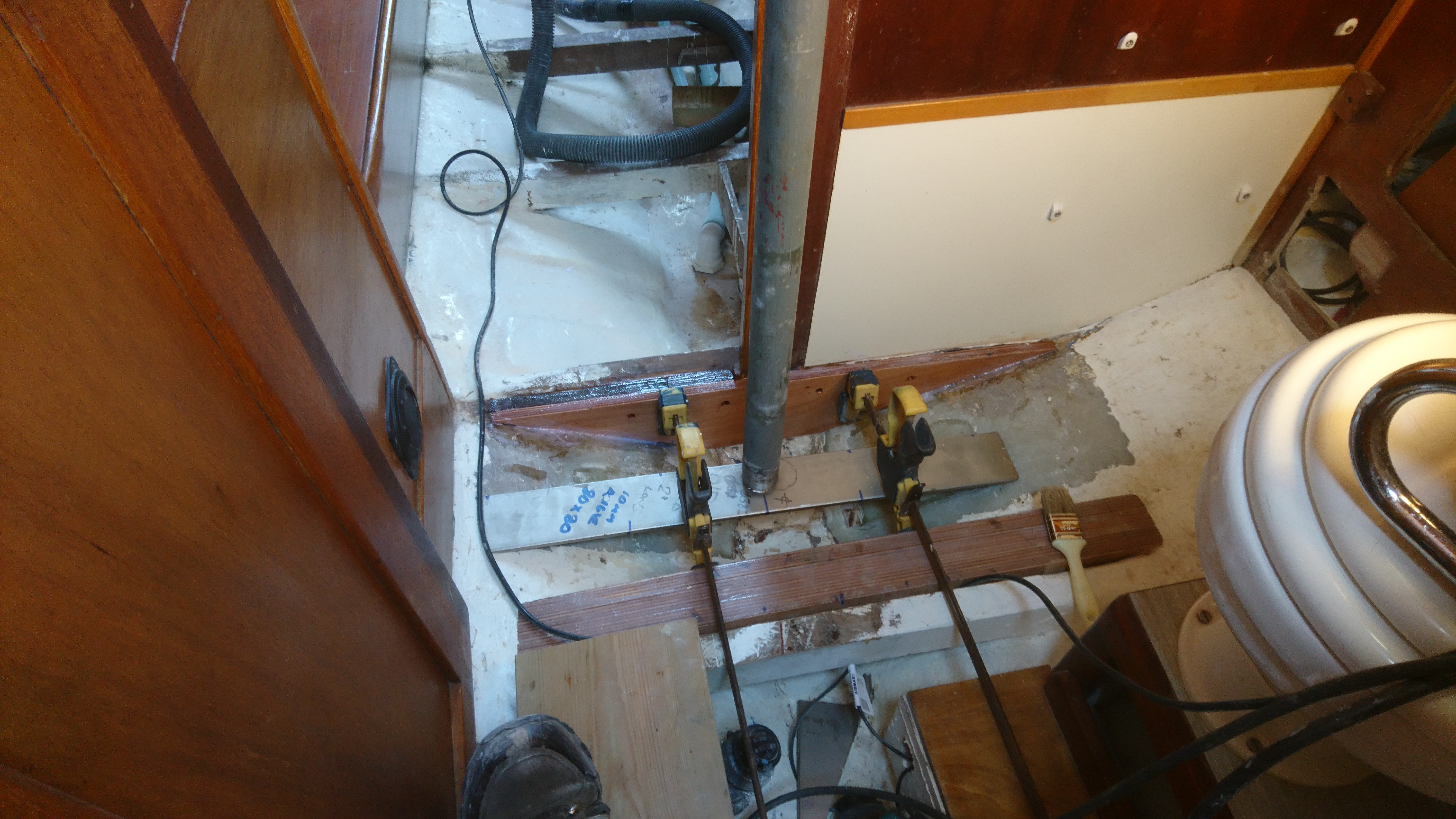
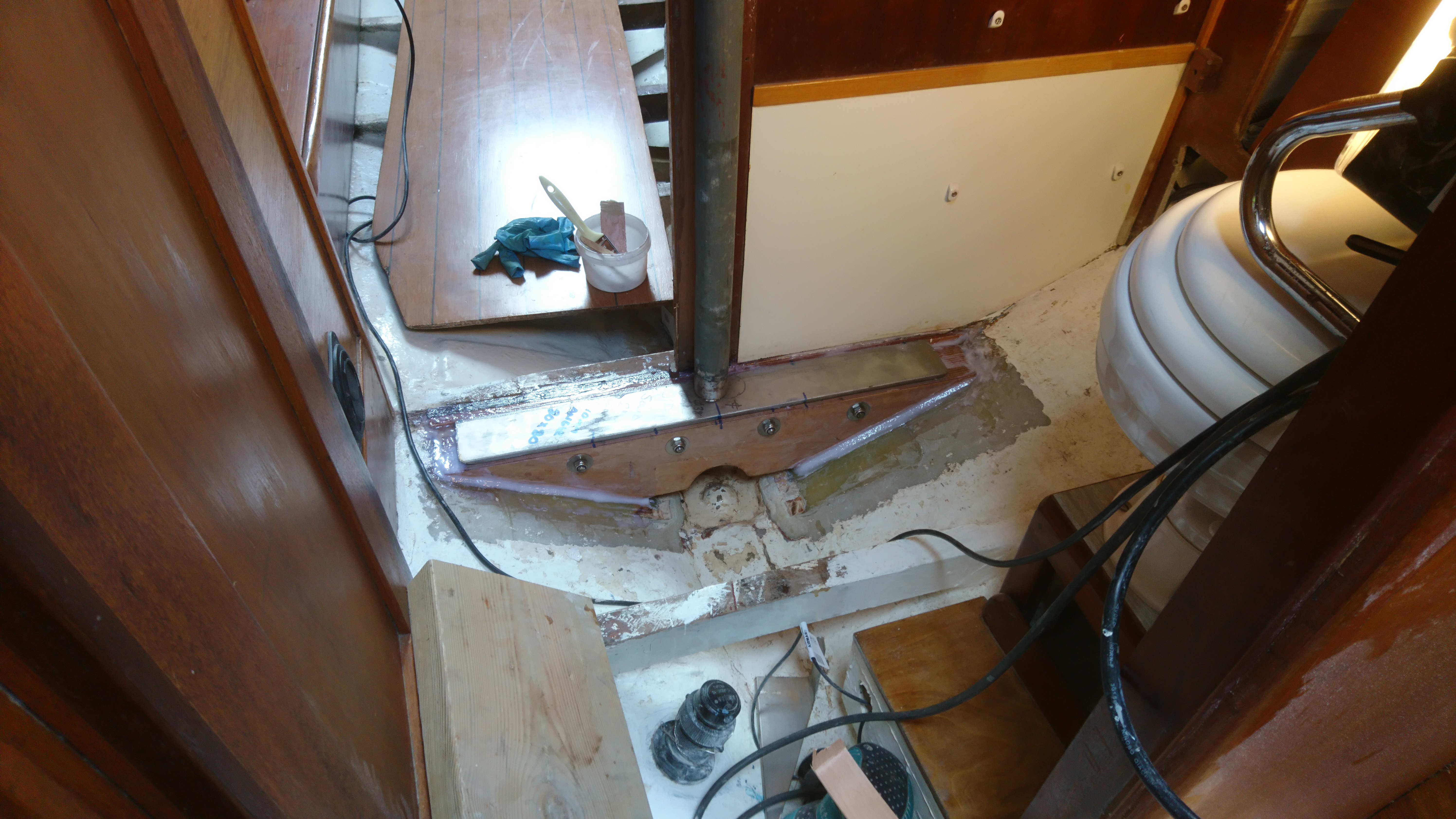
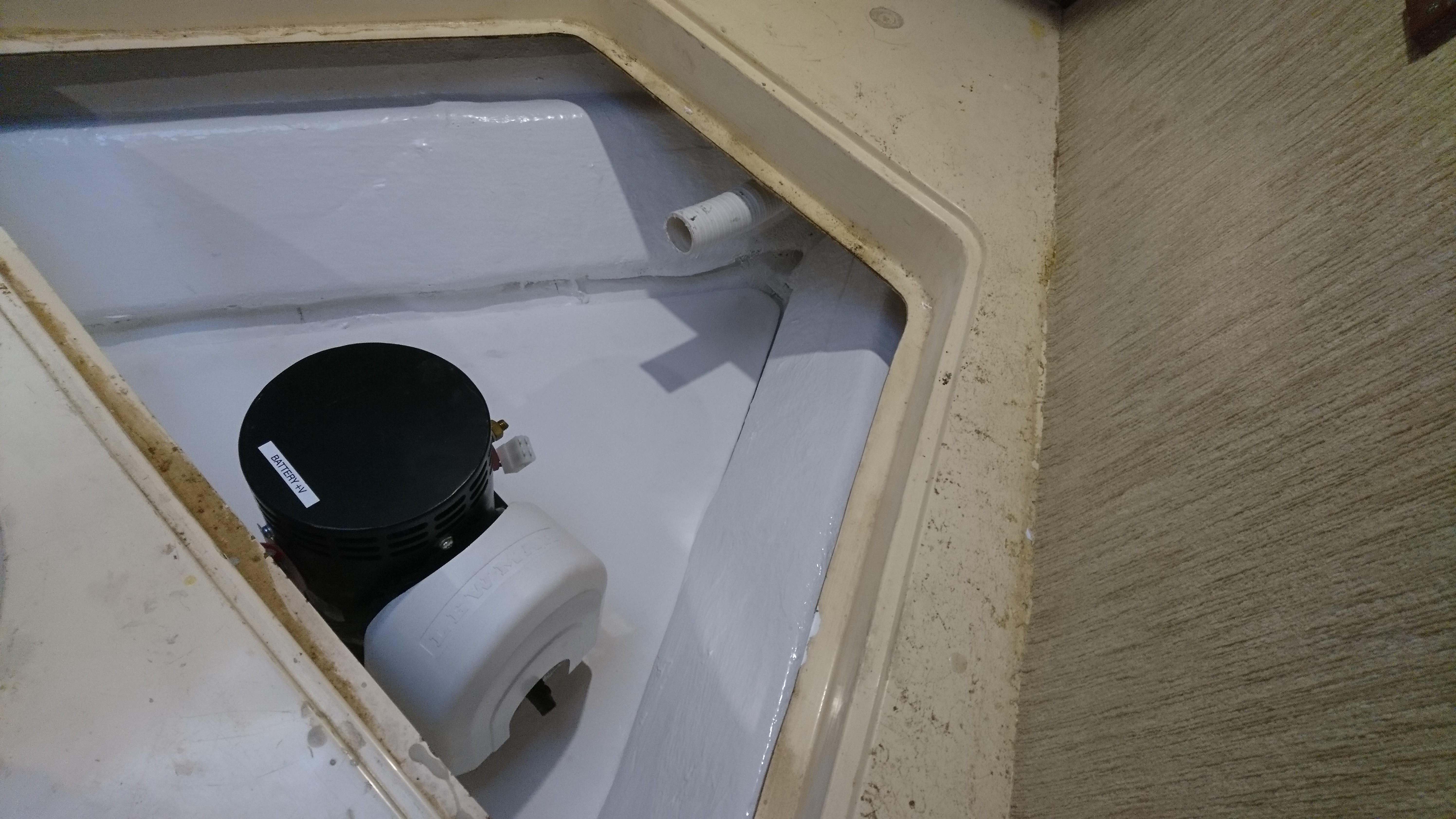
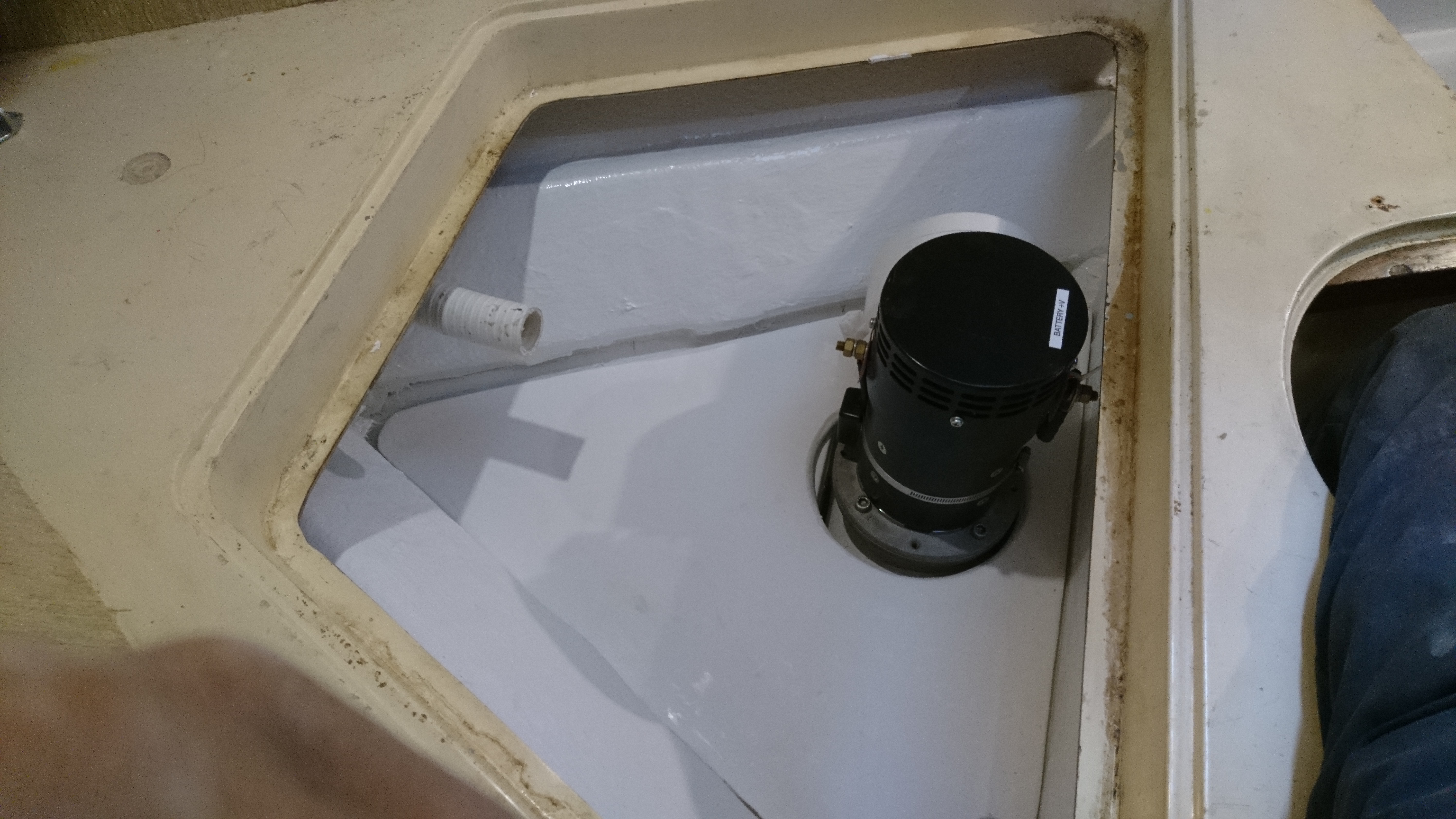
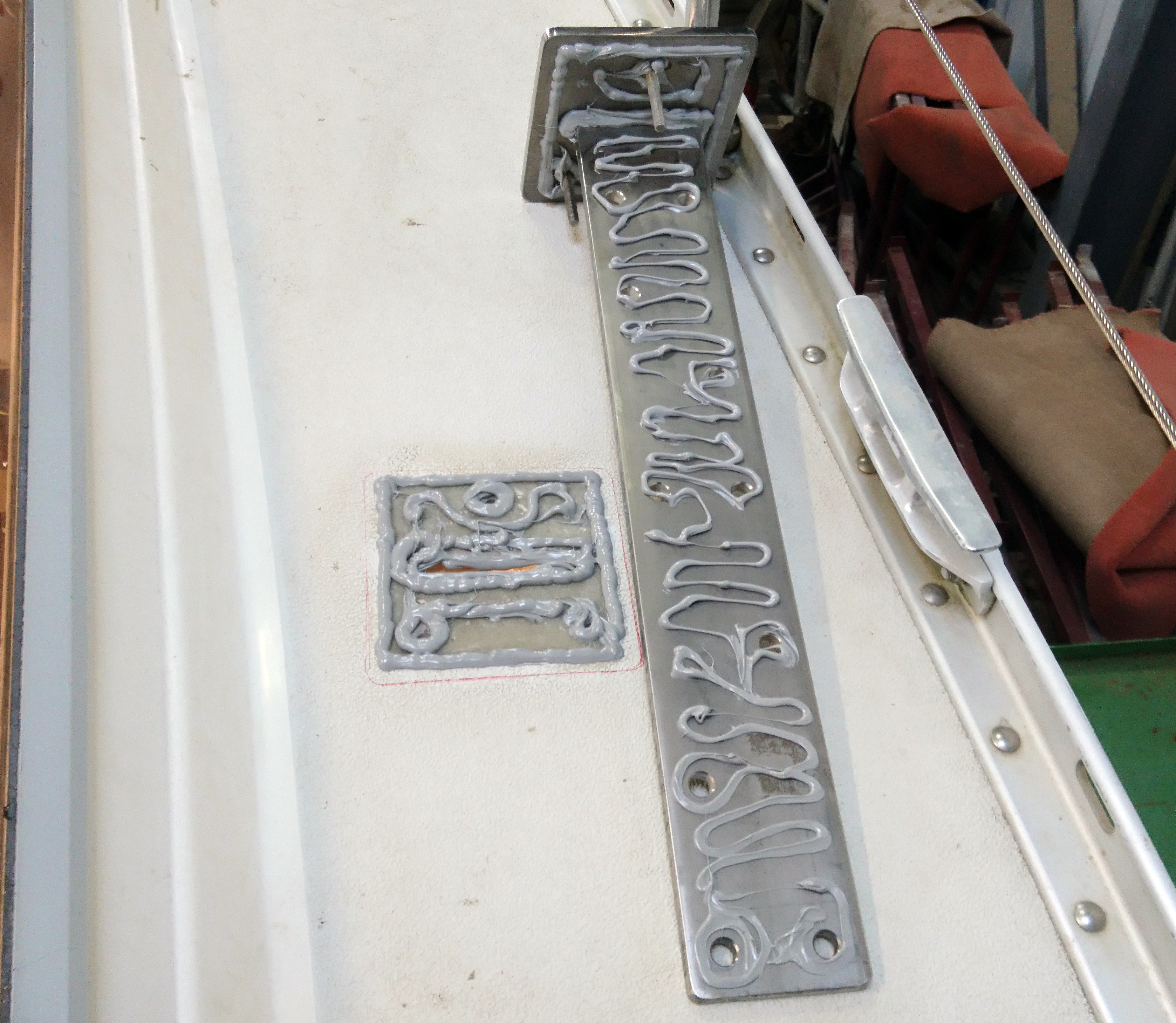
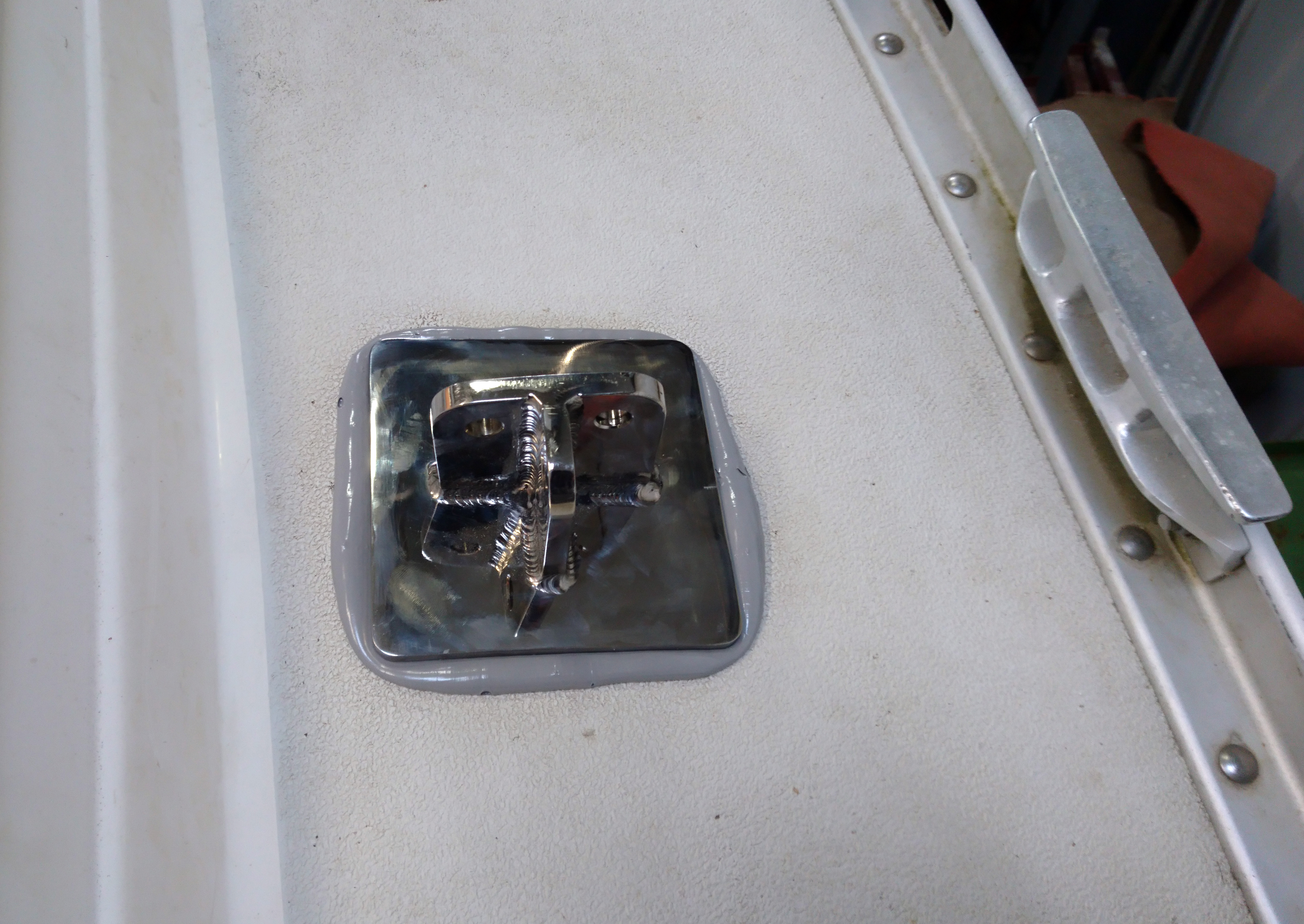
The 220mm ss stud bolts were inserted and partially tightened and a fillet of epoxy added round the rib/hull joint.
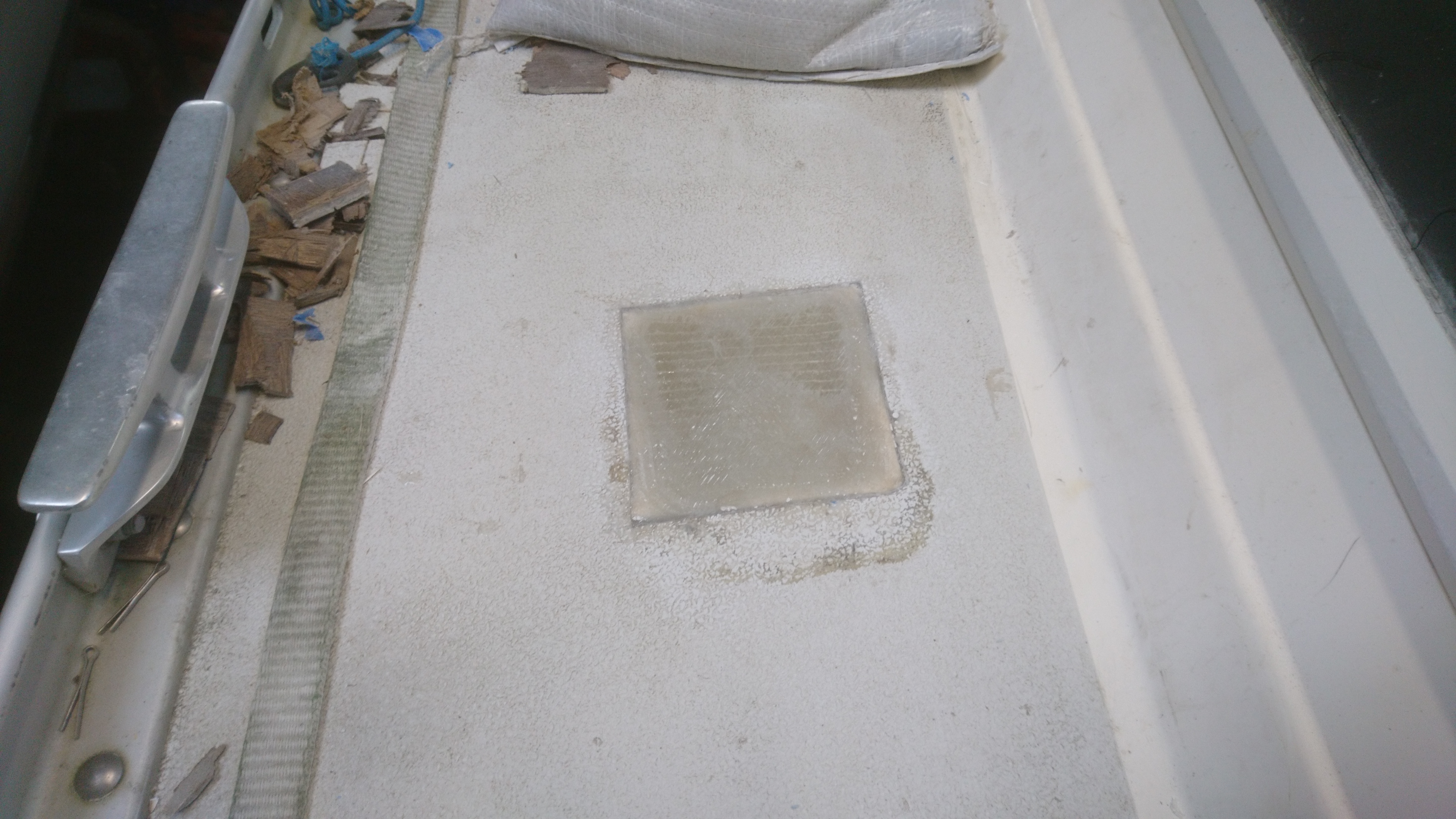
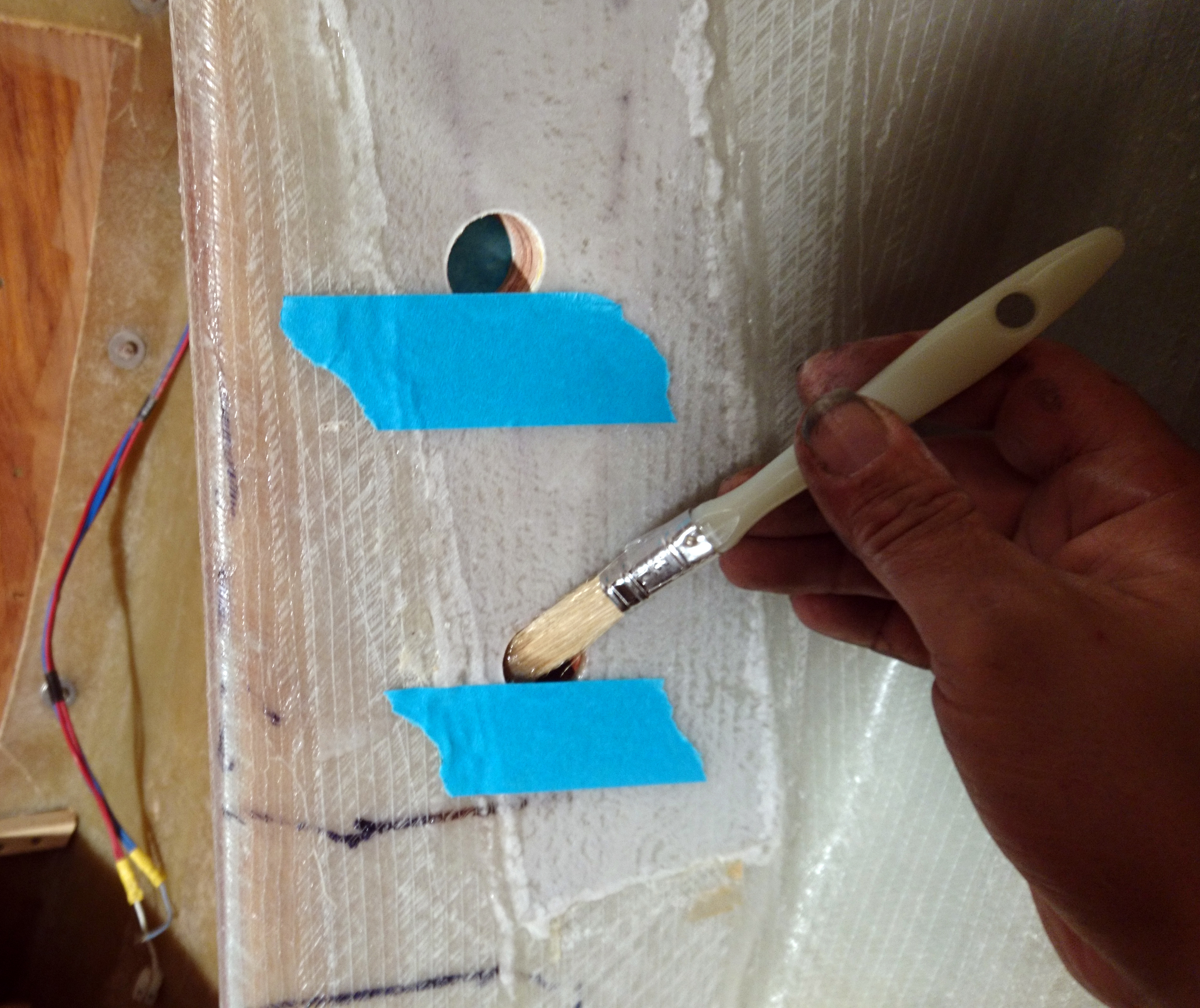
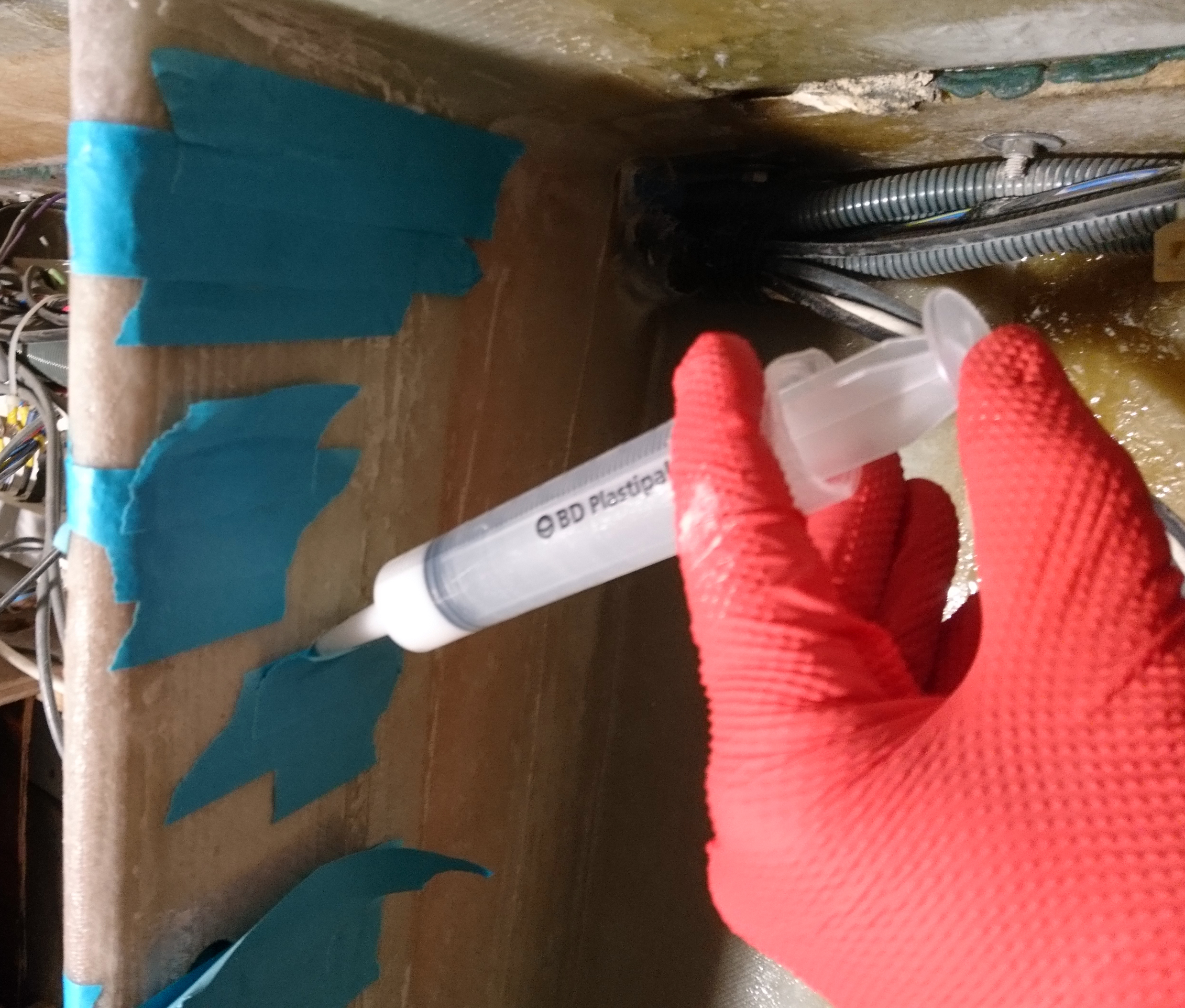
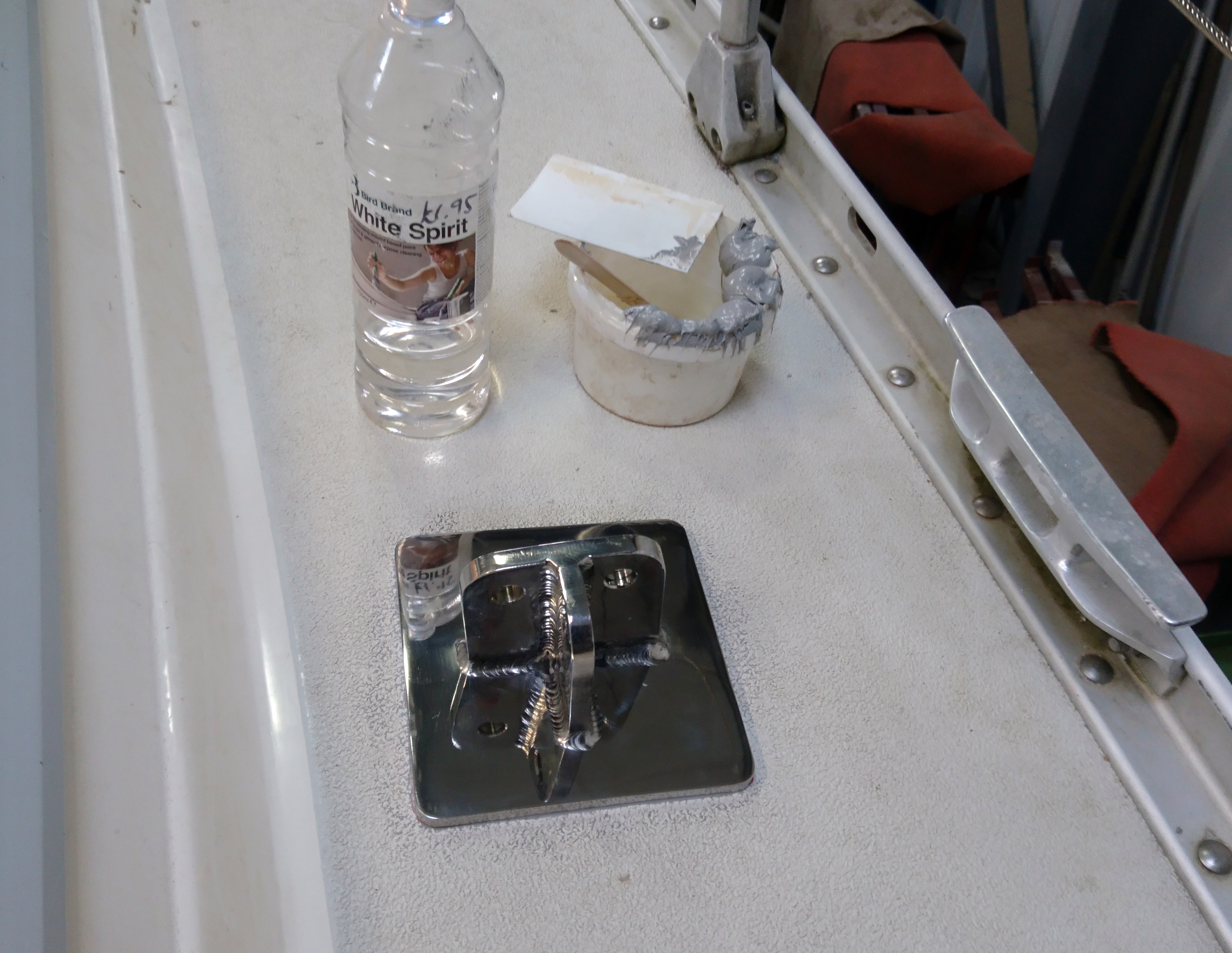
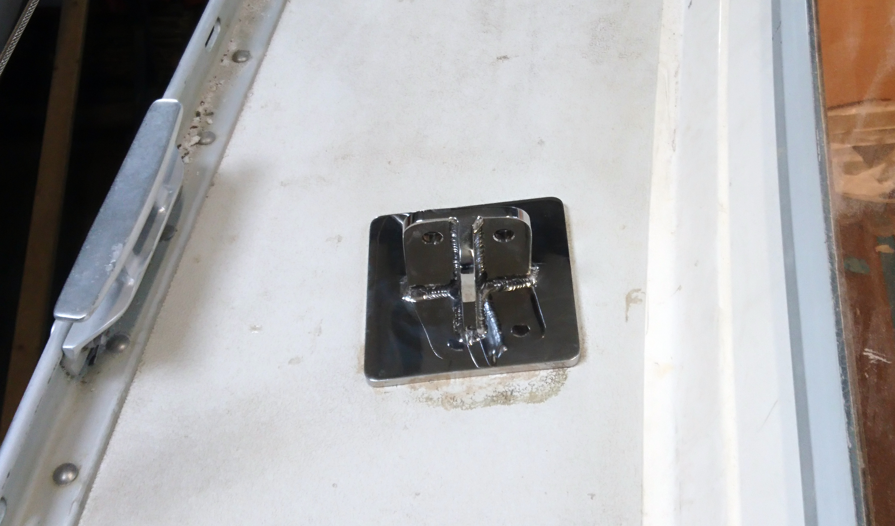
Using a syringe I injected a thickened epoxy mix between the deck and the upper plate.

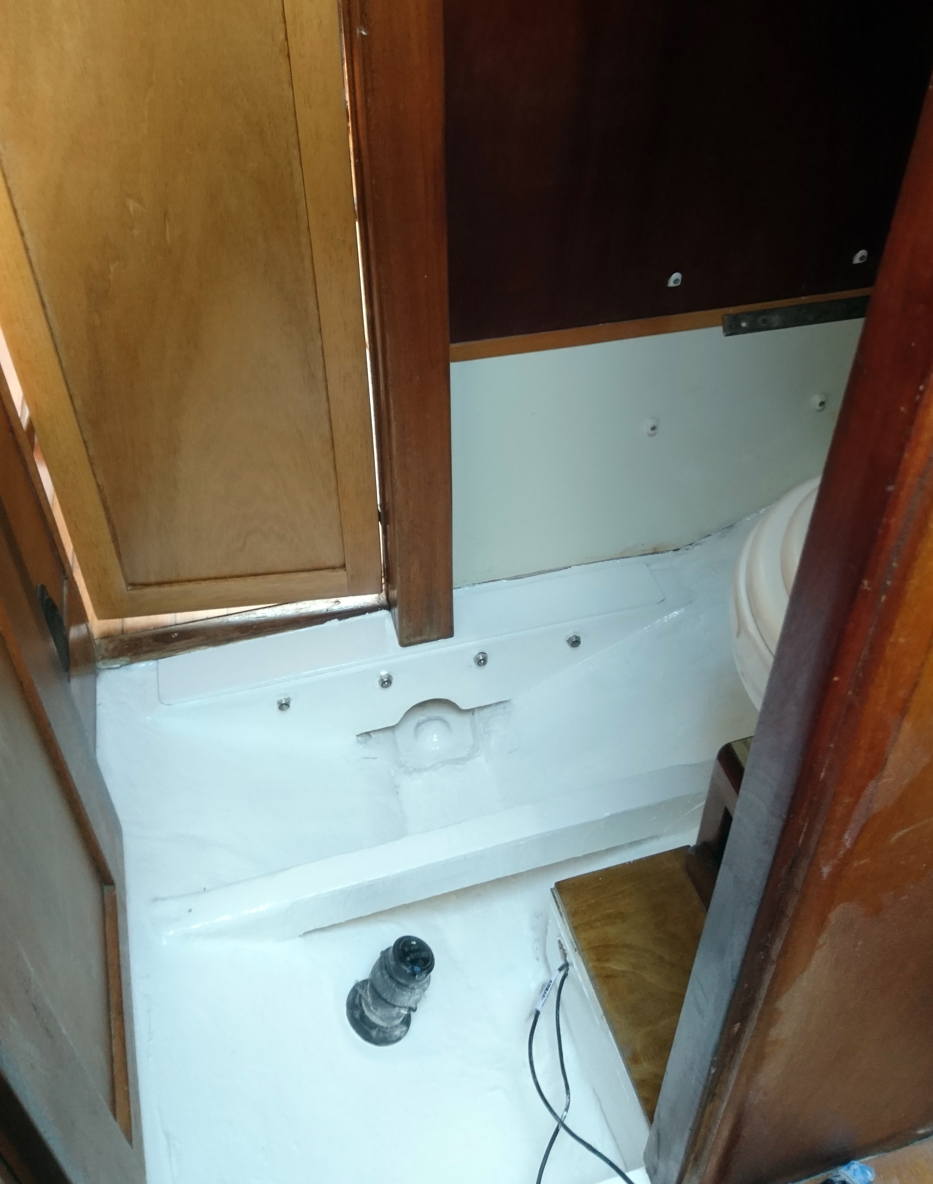
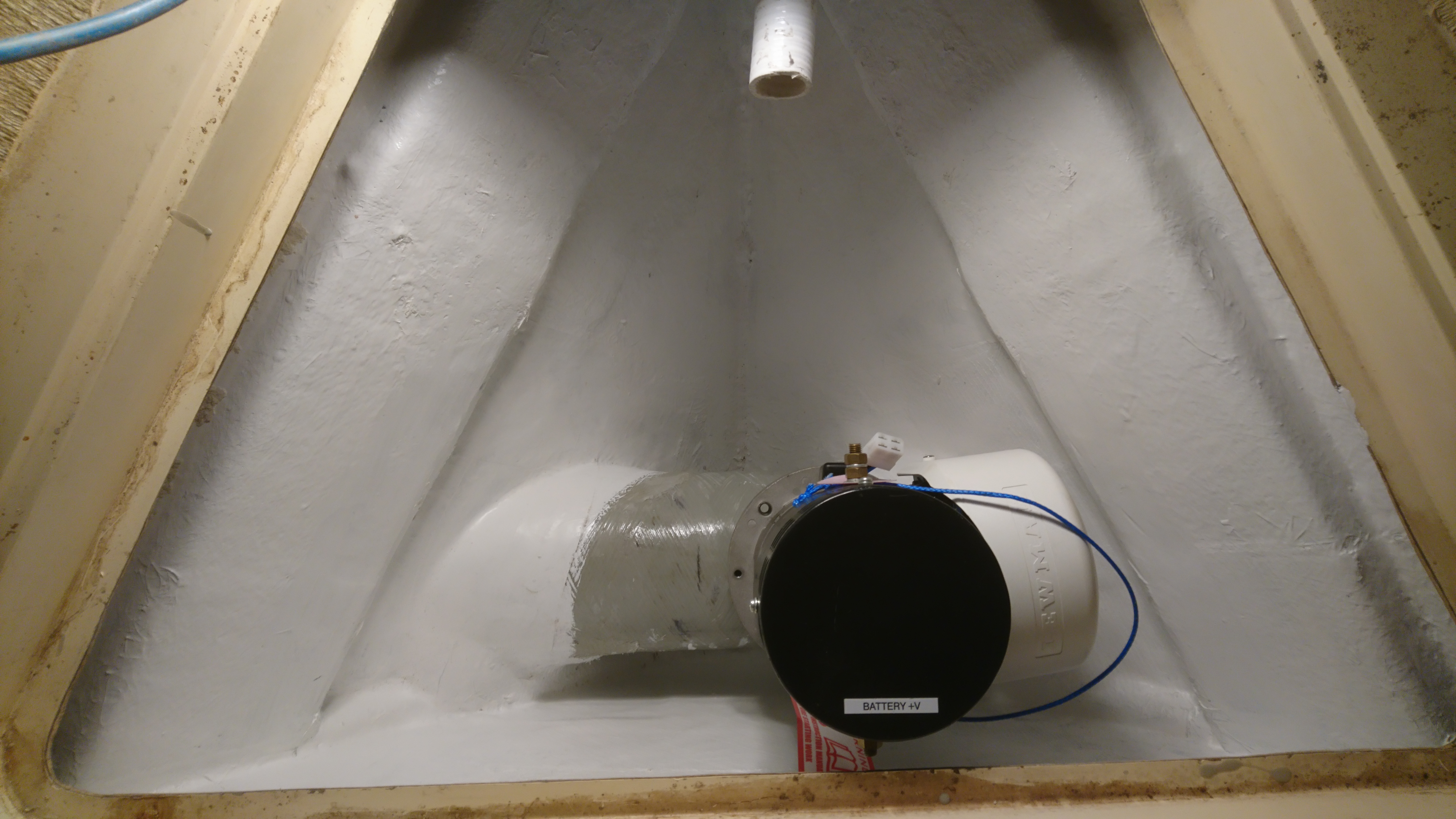
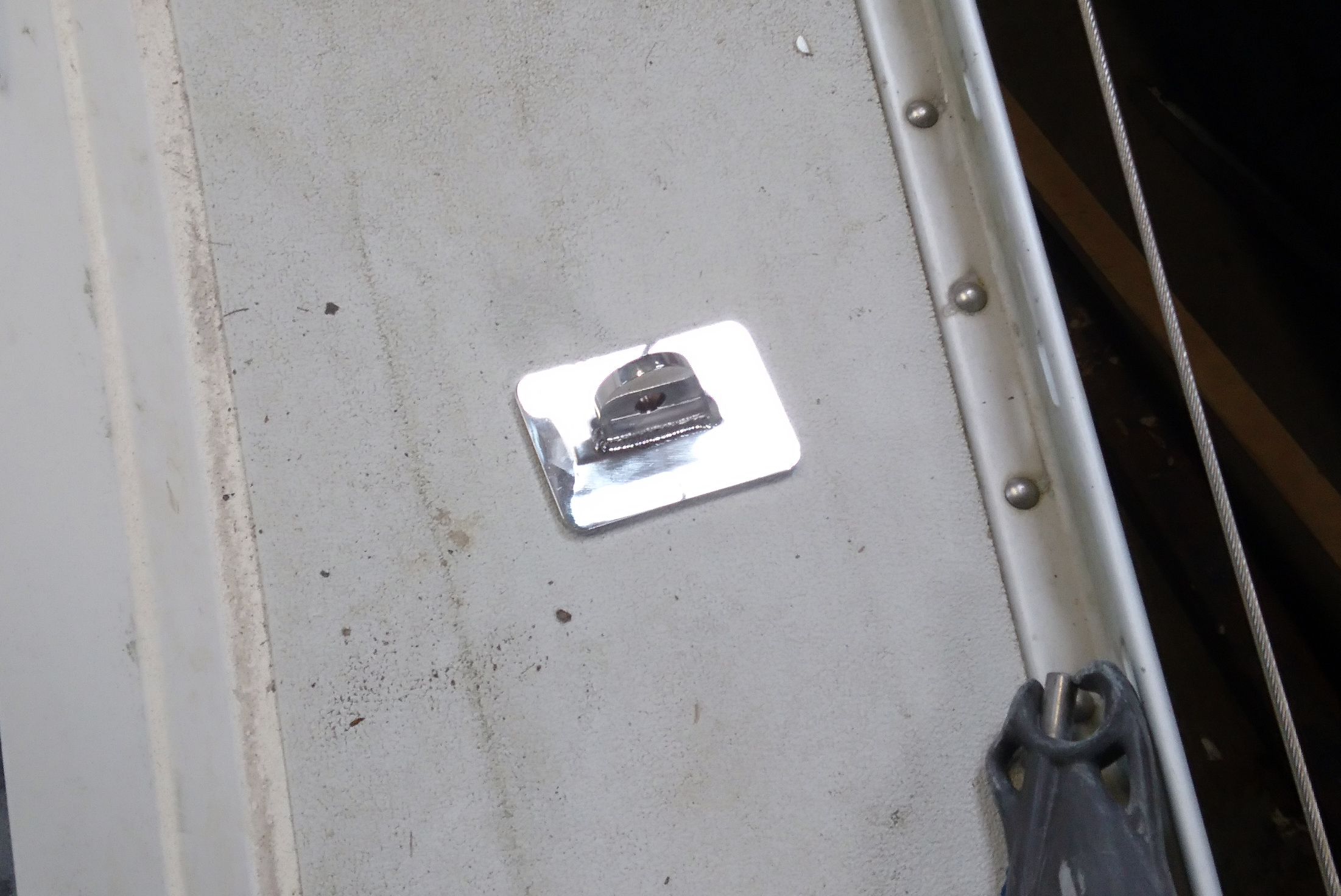
When cured the whole surface was sanded to remove any sharp edges of epoxy and remove the cure blush before applying two coats of Damboline.
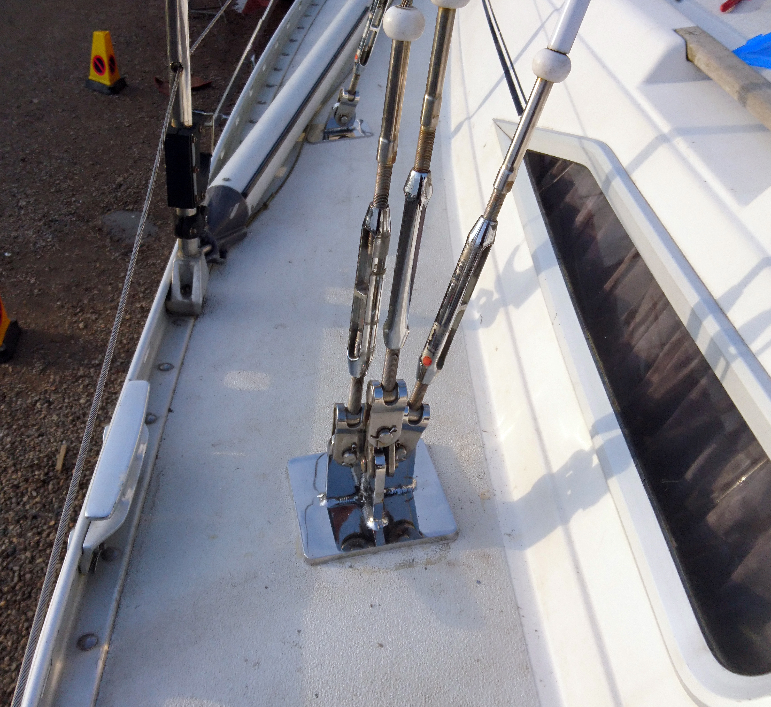
The bolts through the bulkhead were tightened up using plate washers and ss nylock nuts, followed by the upper through deck boats using Arbokol as the bolt sealant.
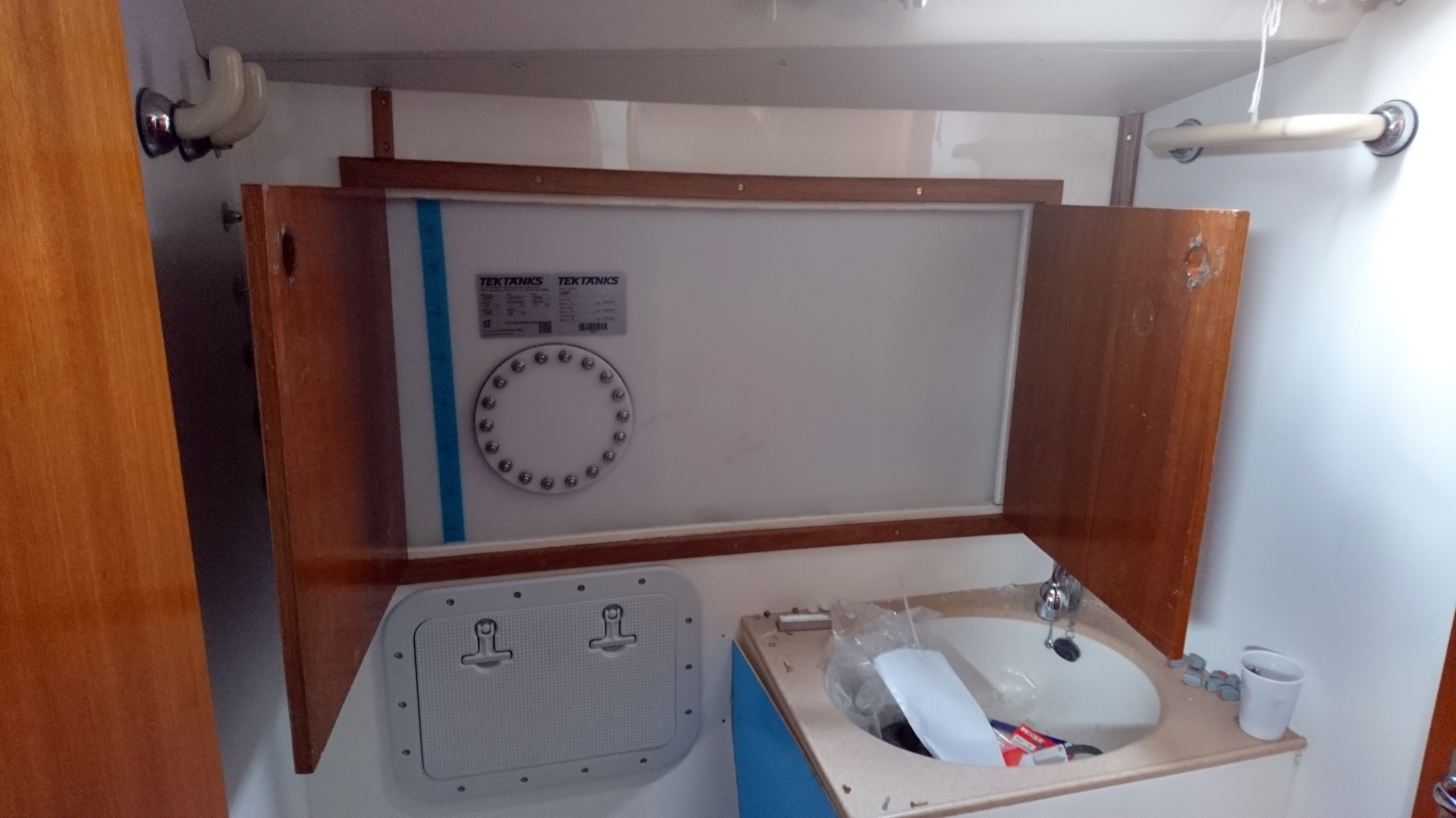
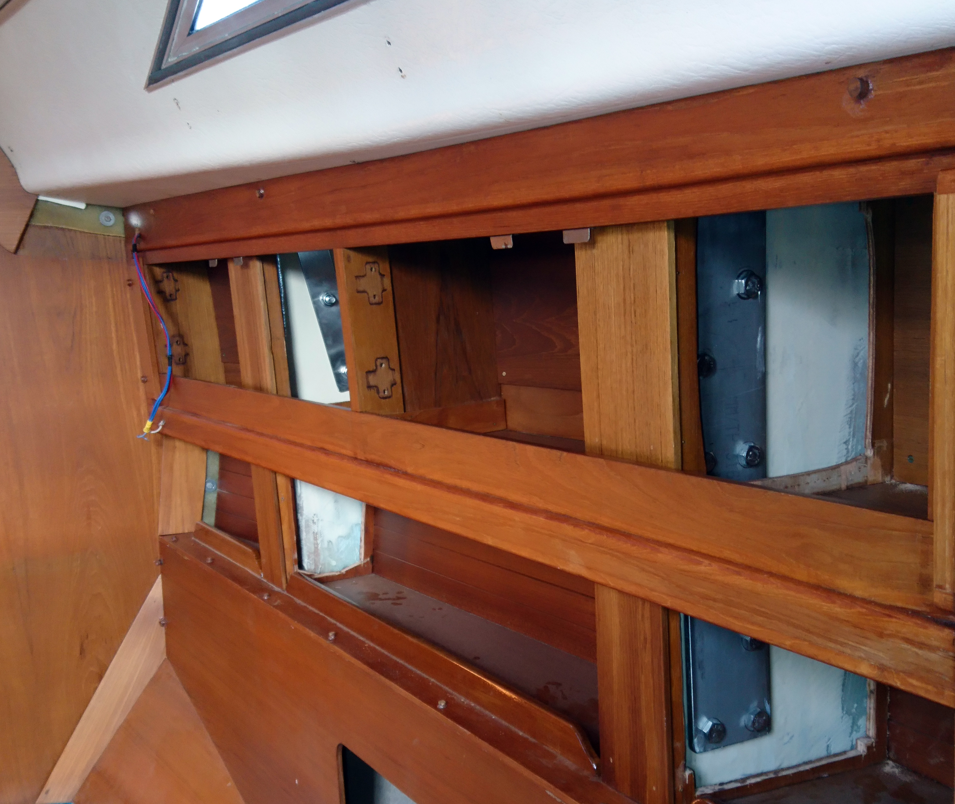
Finally it was just a case of re stepping the mast, setting up the rig and putting back the interior trim that had been removed to gain access.
As I finished this job a Nauticat 36 was sold locally and the survey picked up a major problem with its compression post.
Guess I know what I’m doing in a few weeks time…….


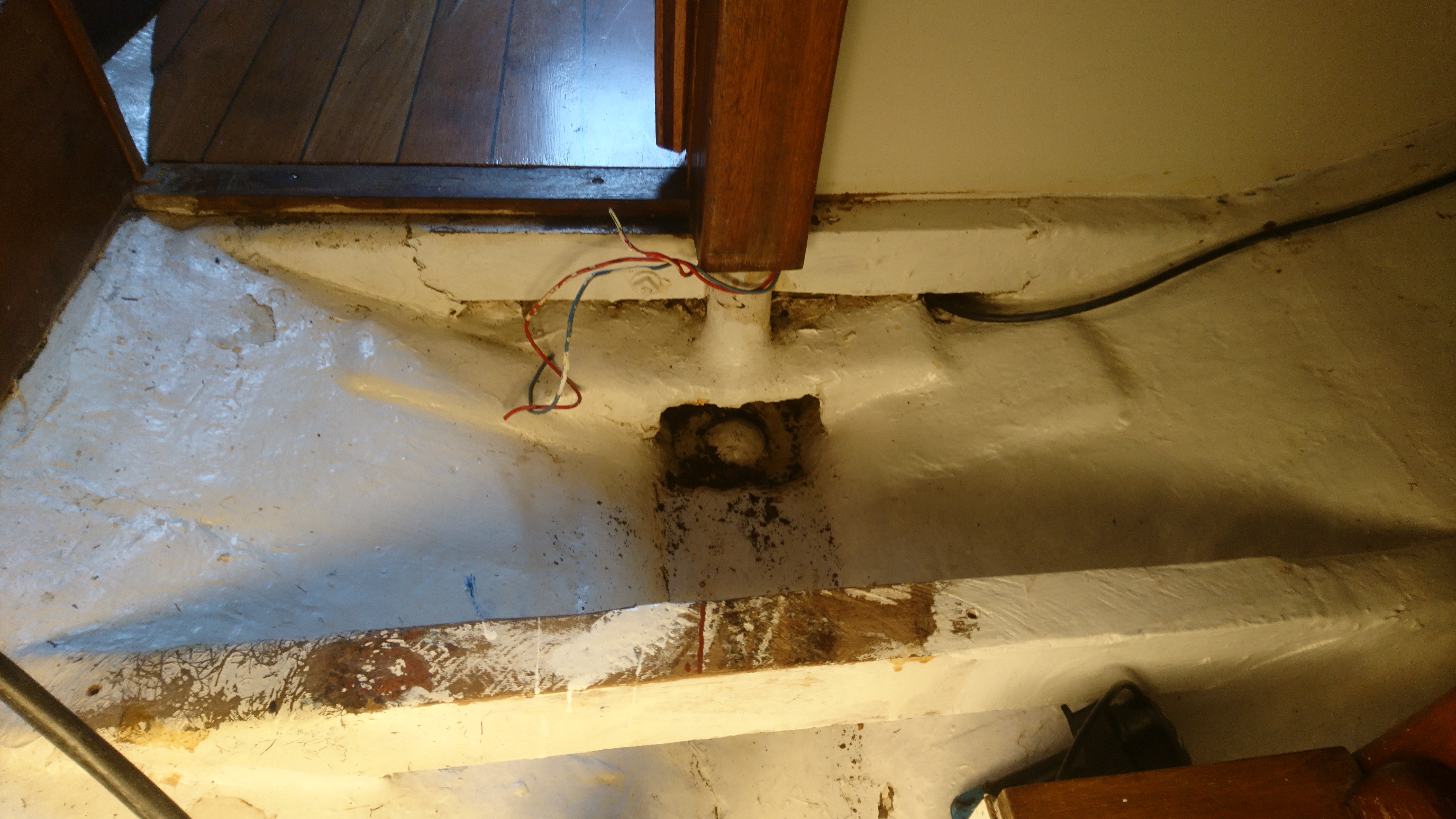
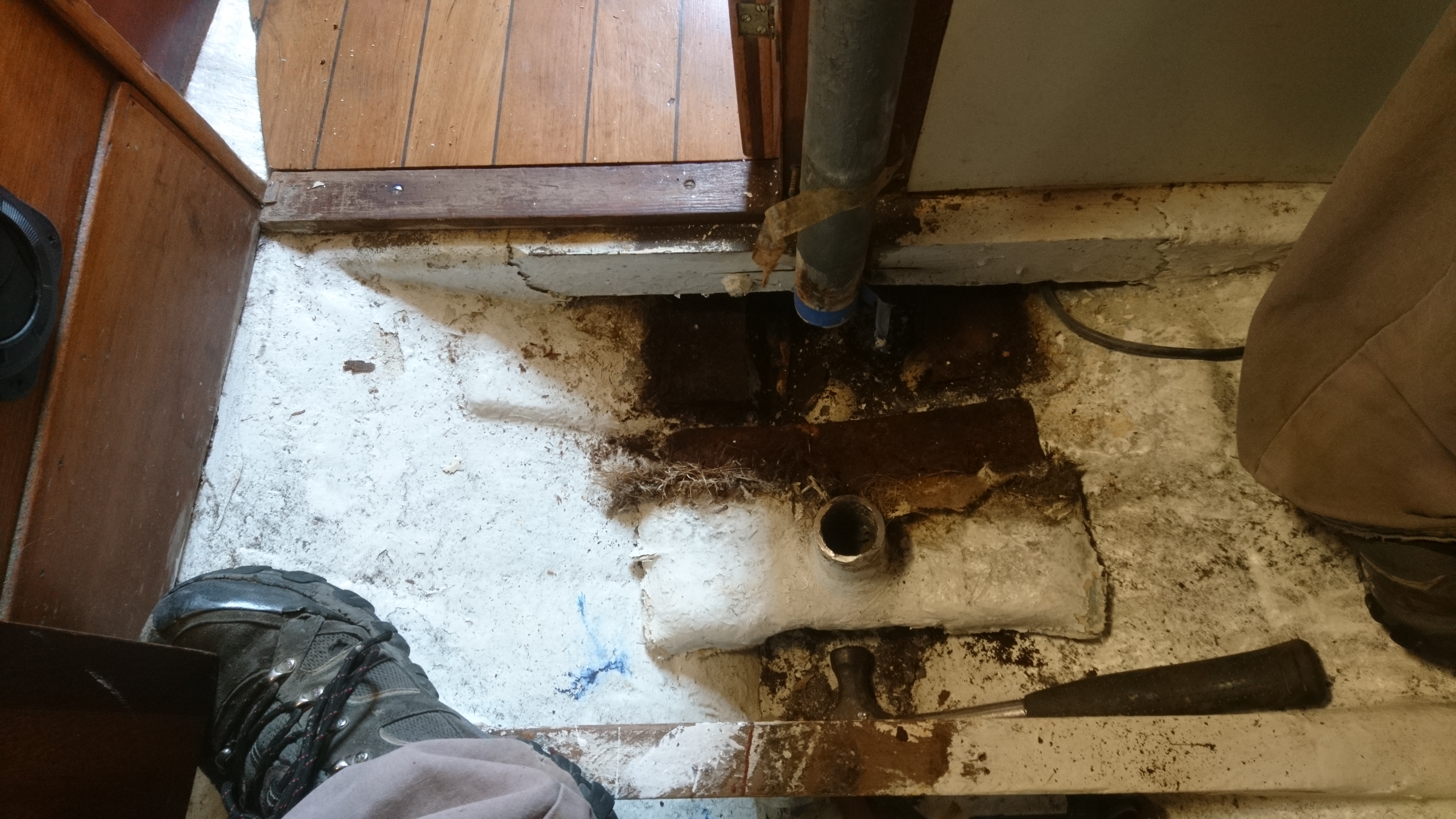
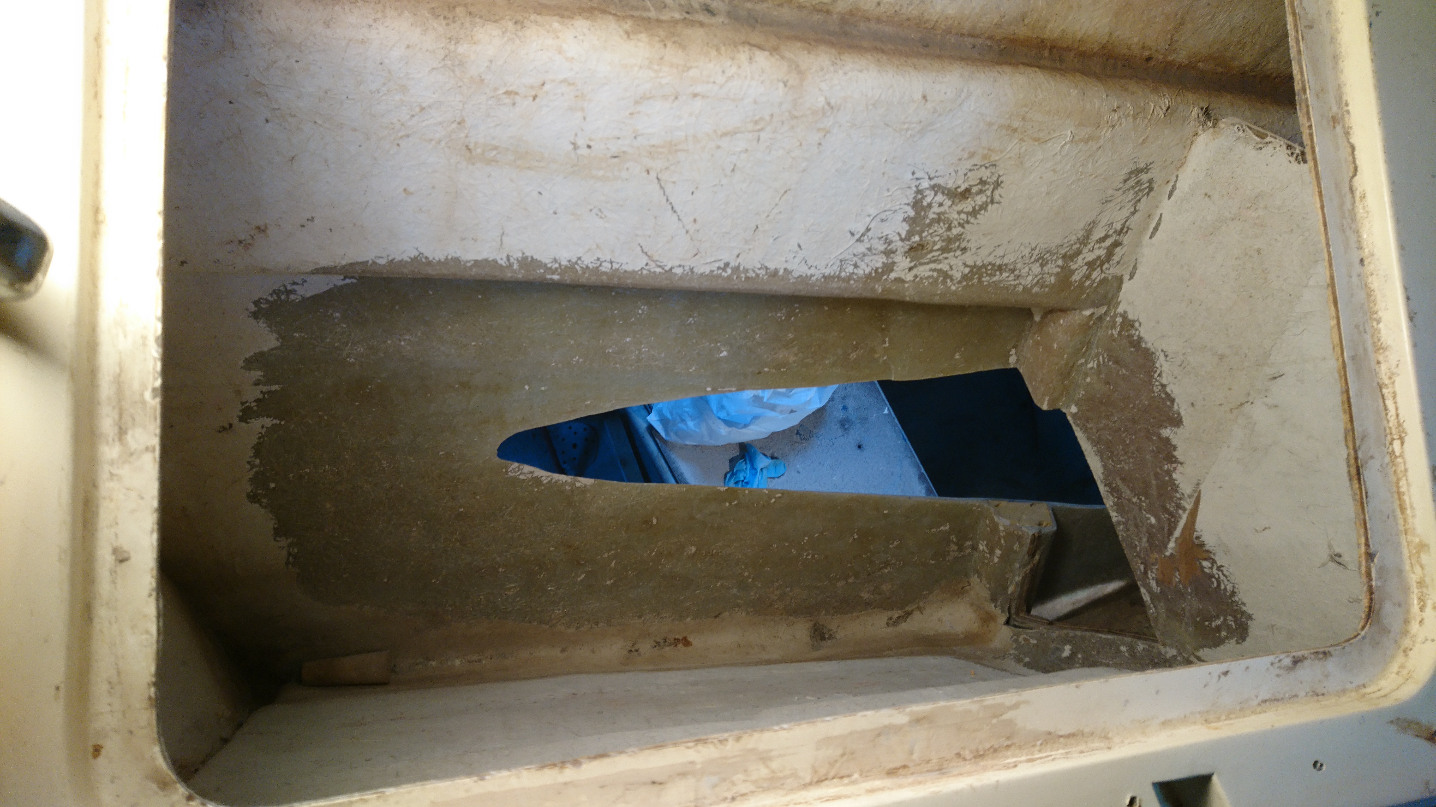
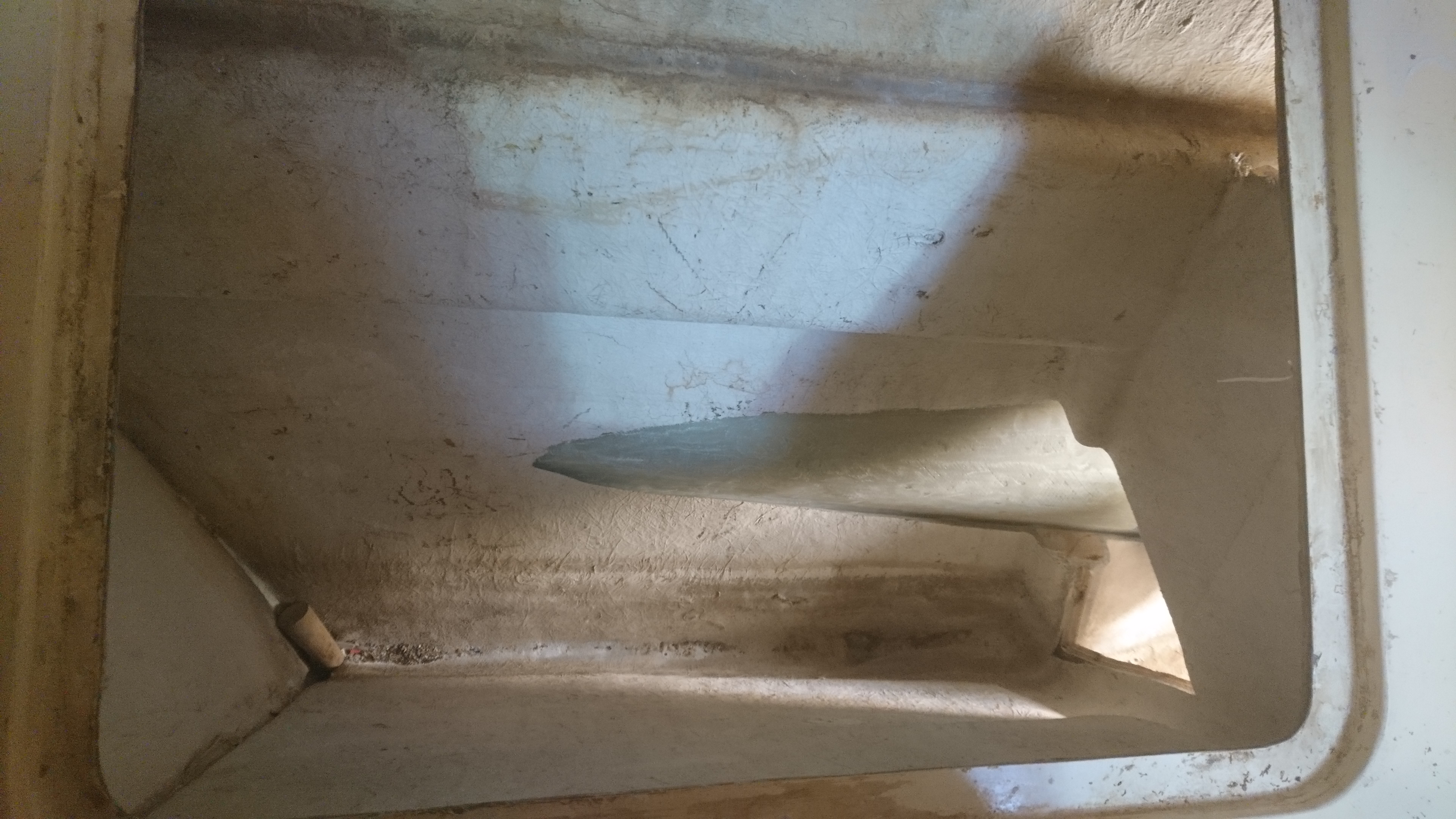
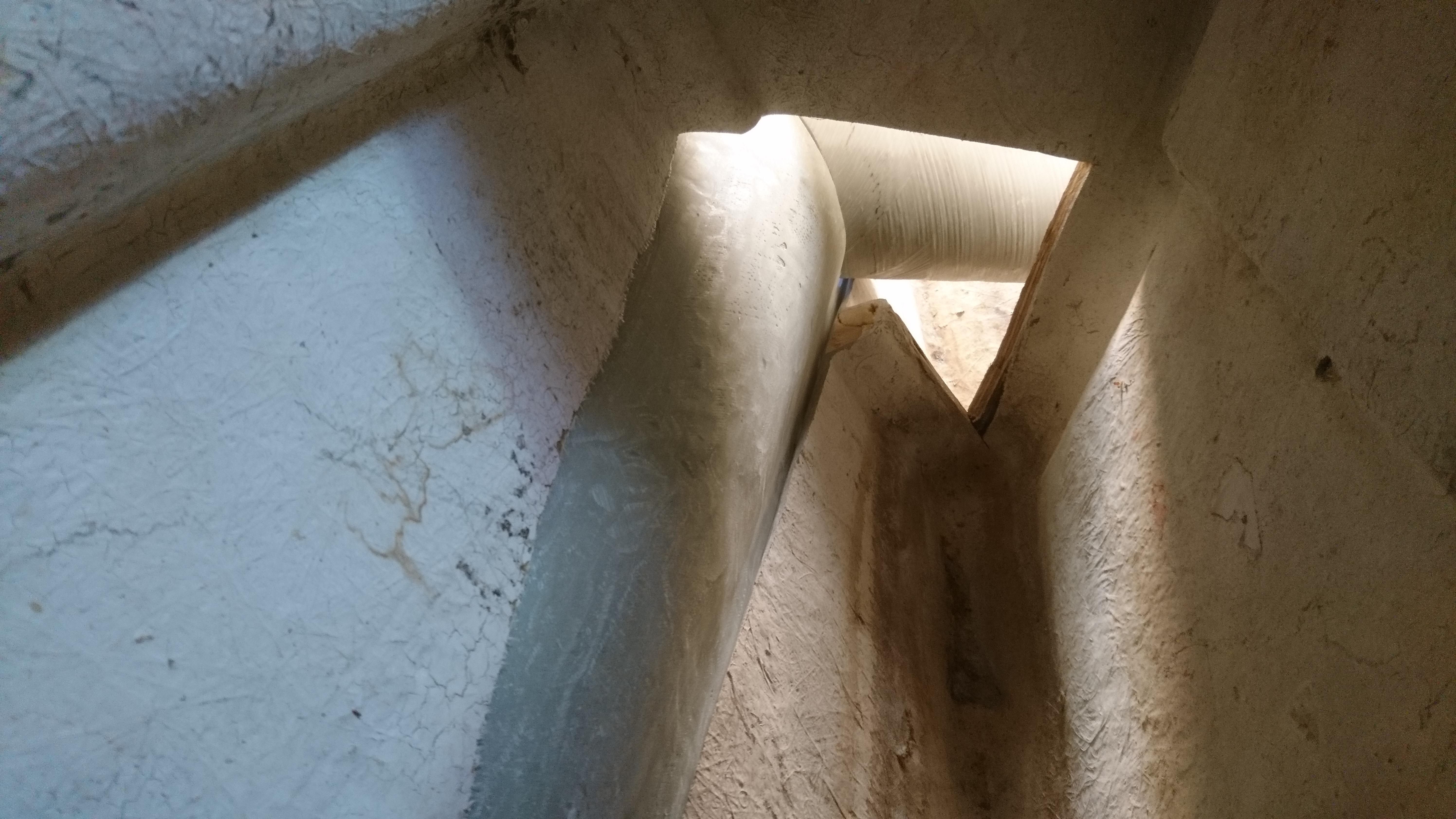
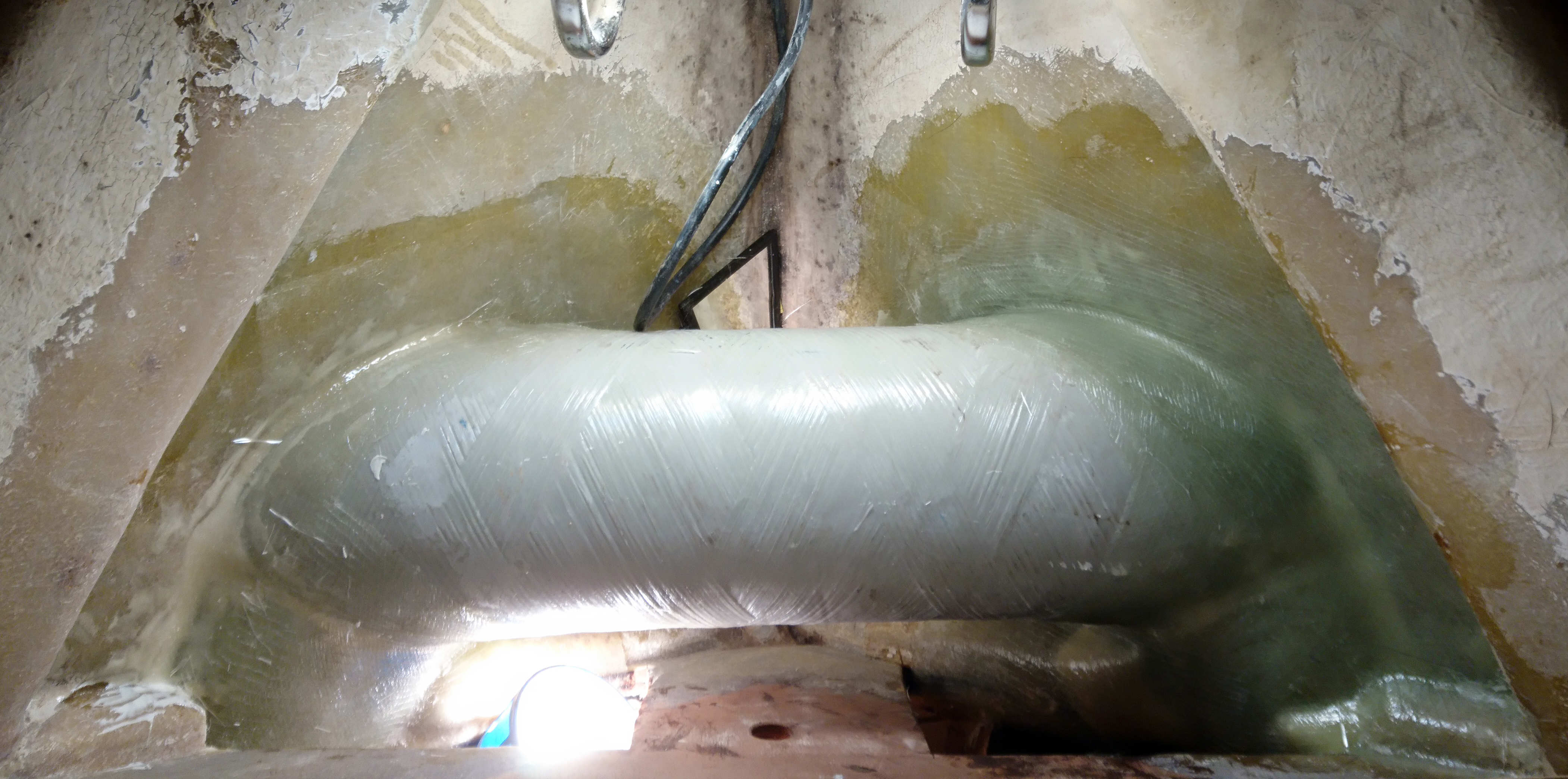
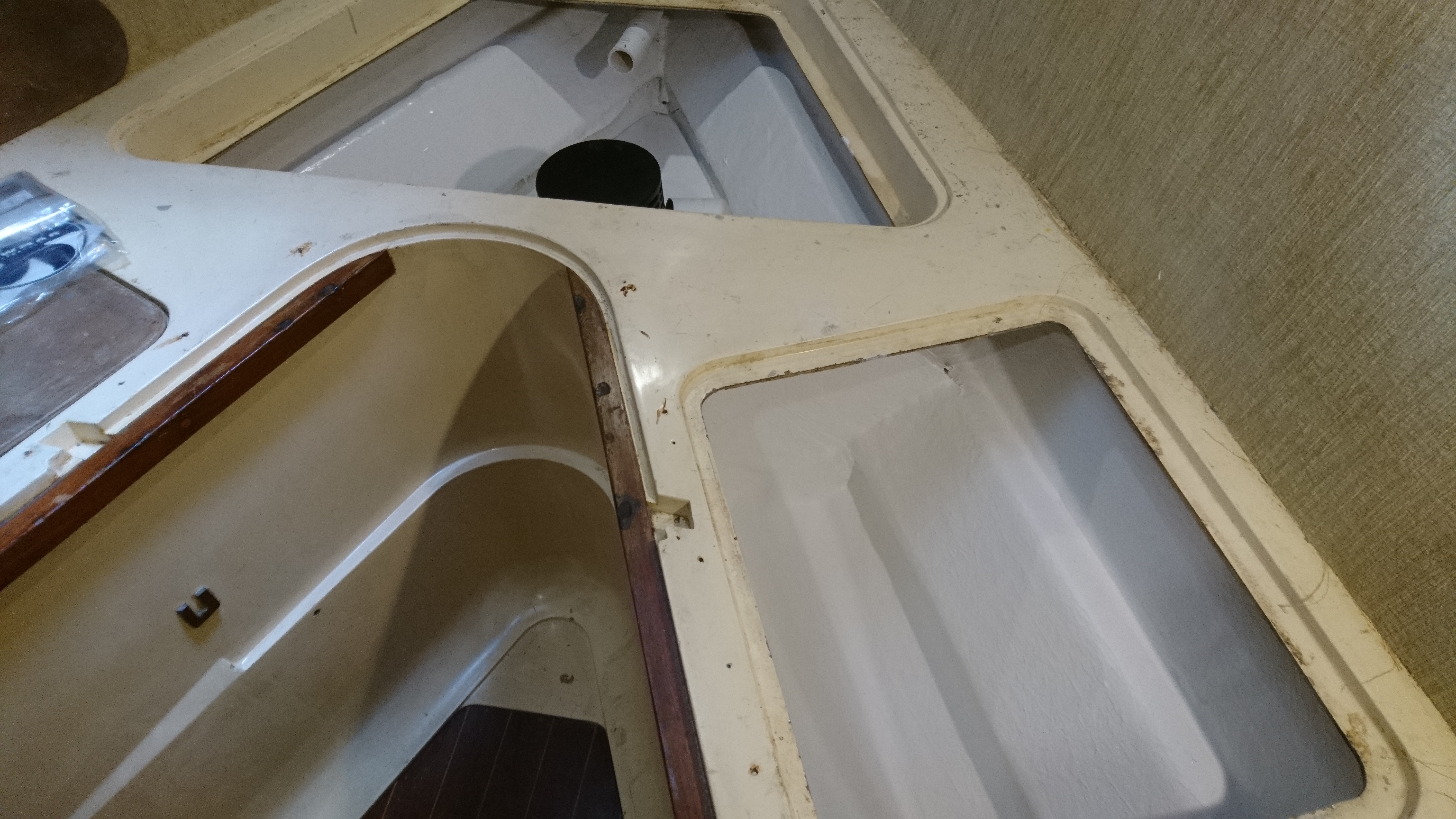
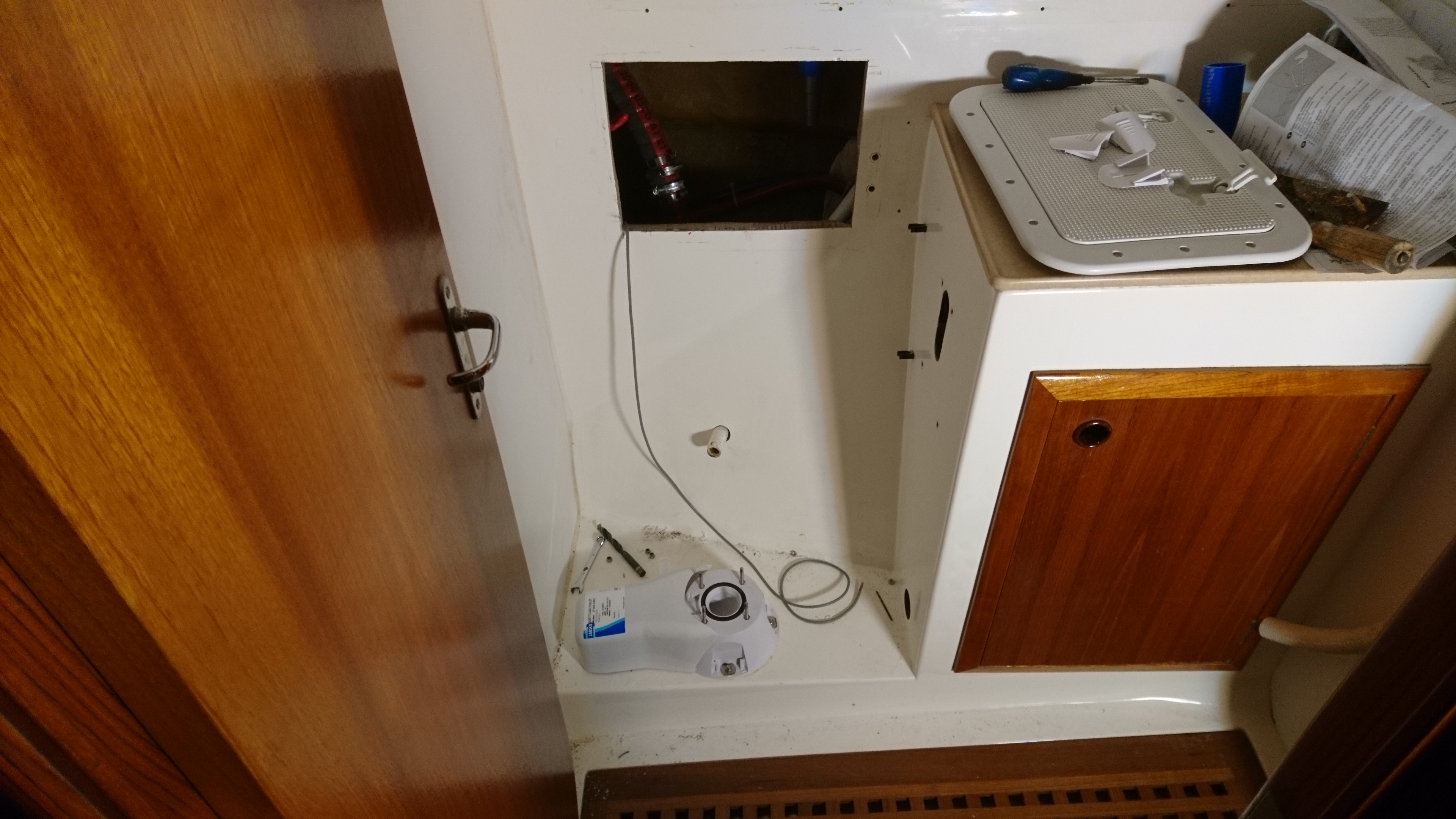
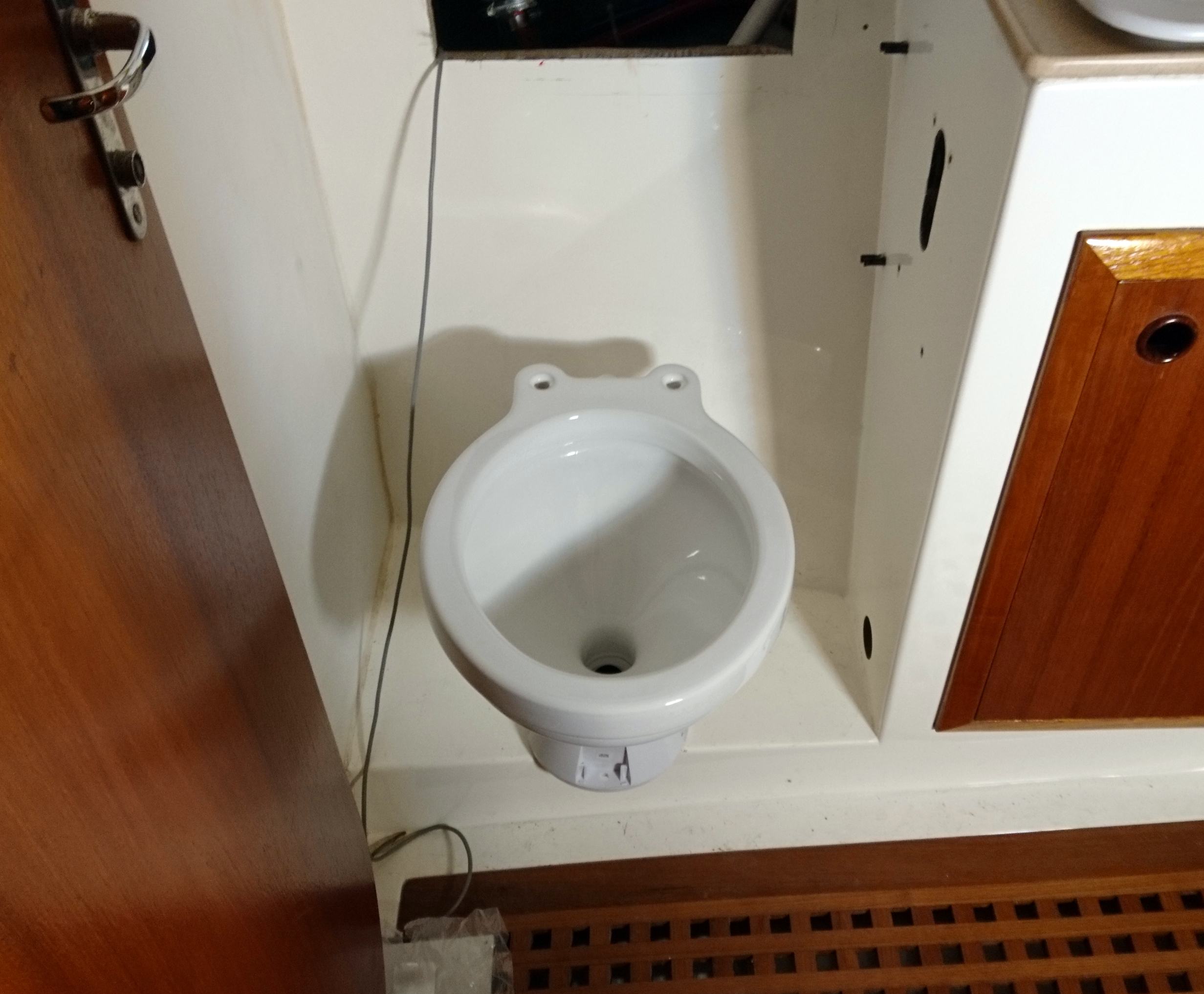
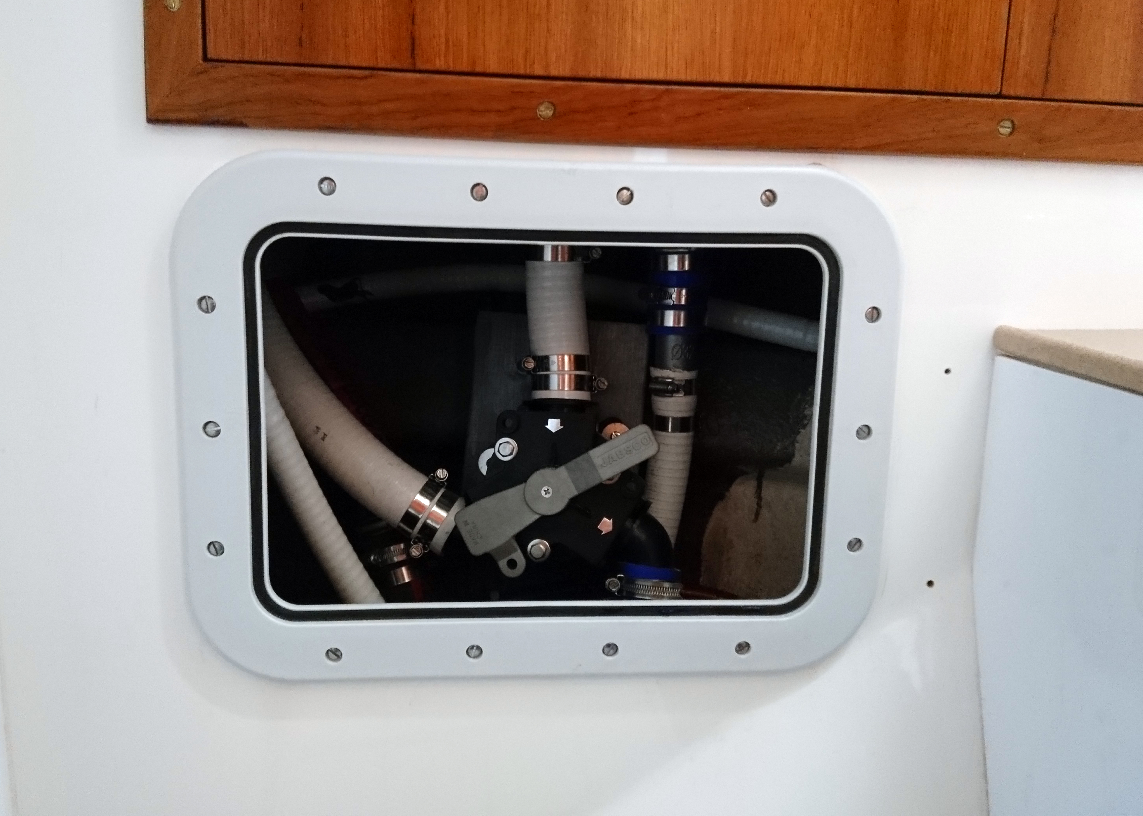
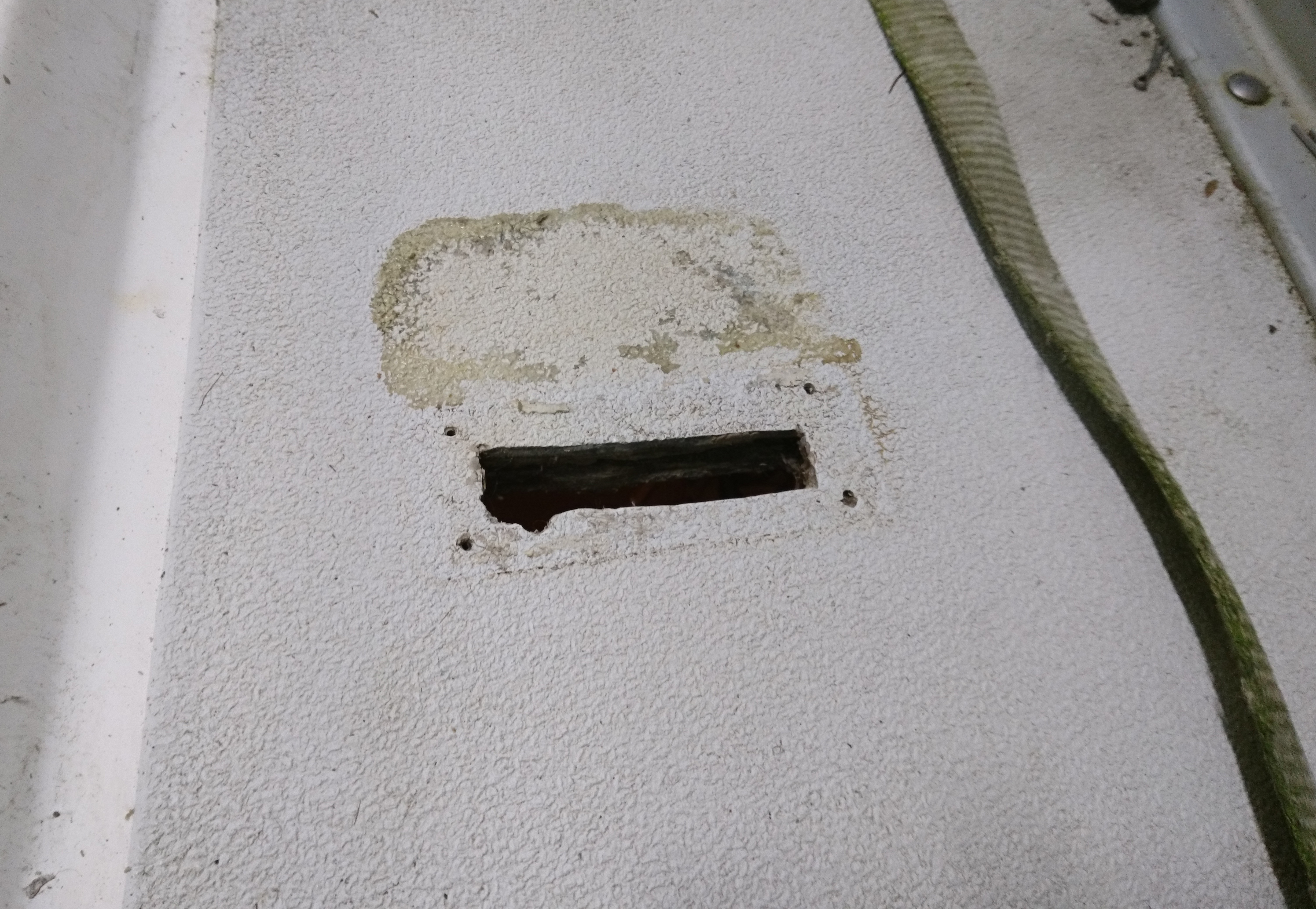
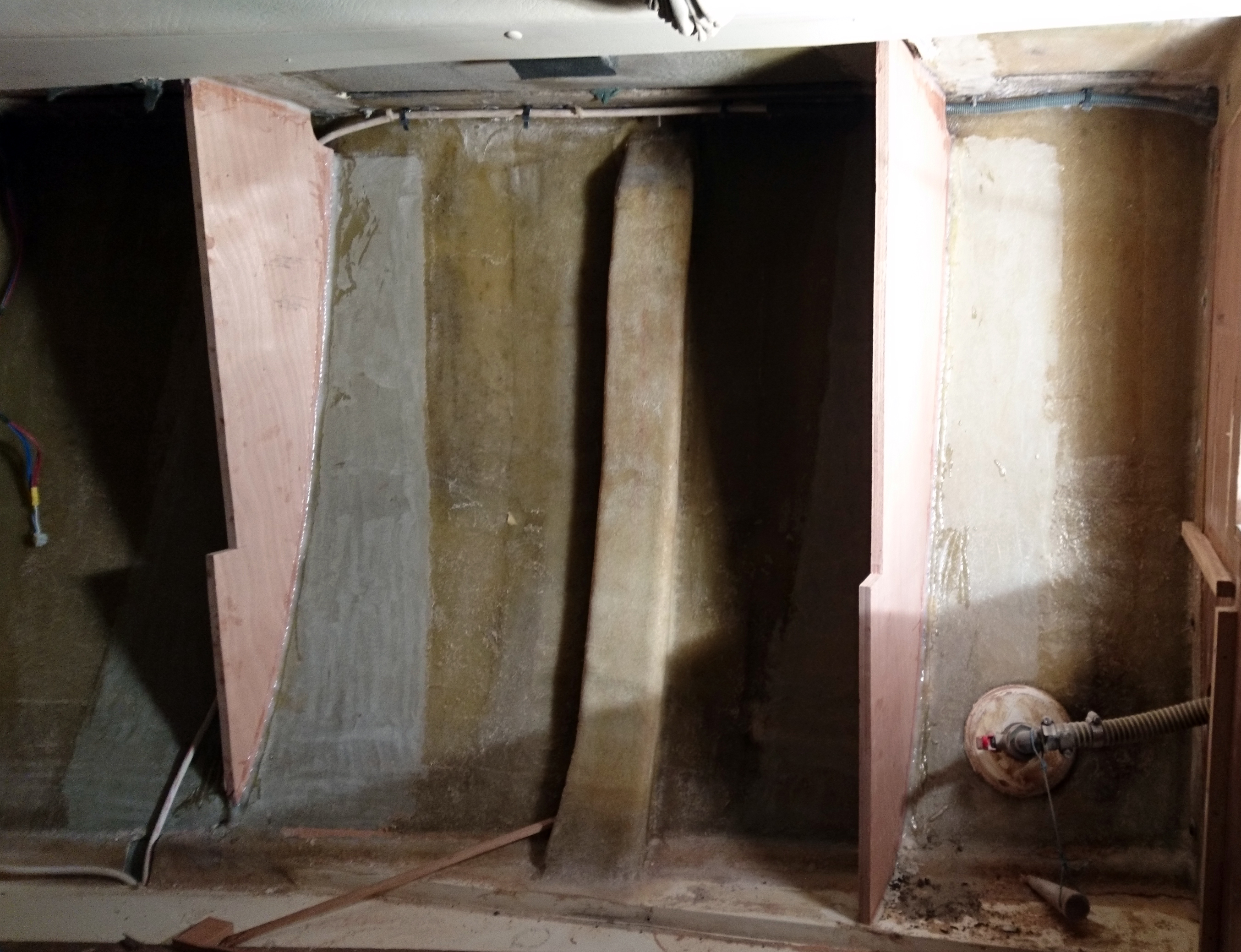
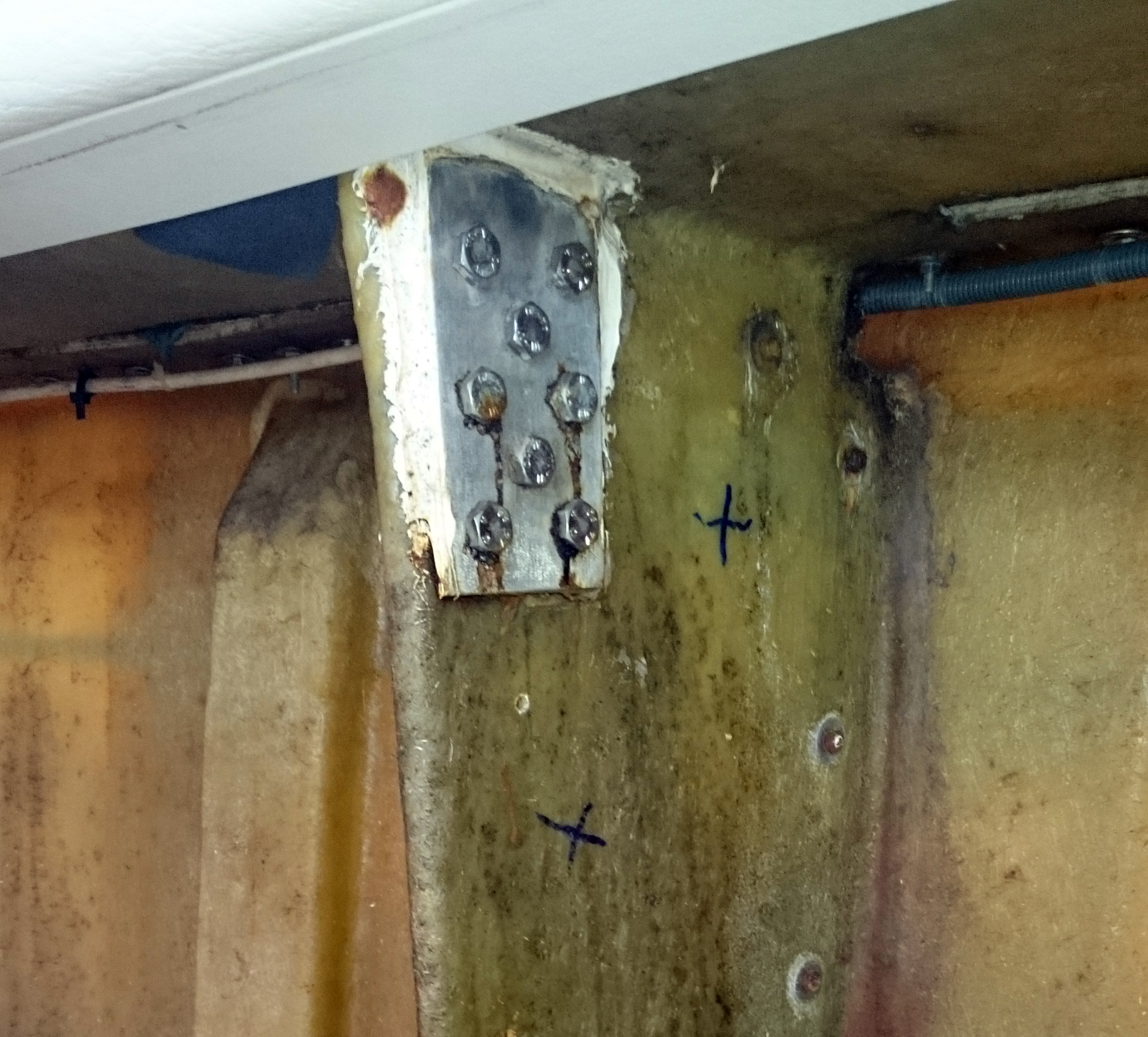
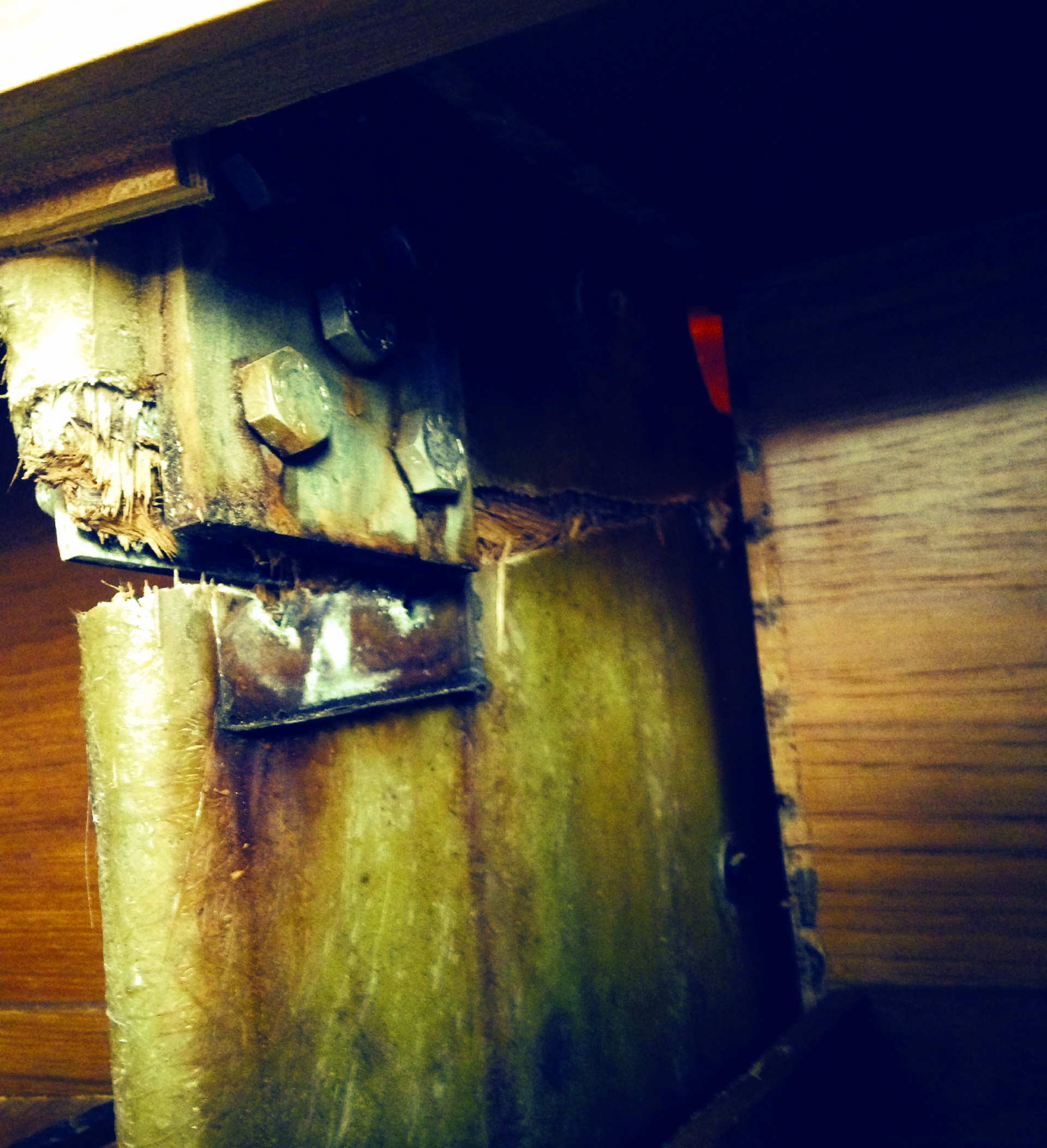
The failure of the bridge over the keelbolt is plain to see

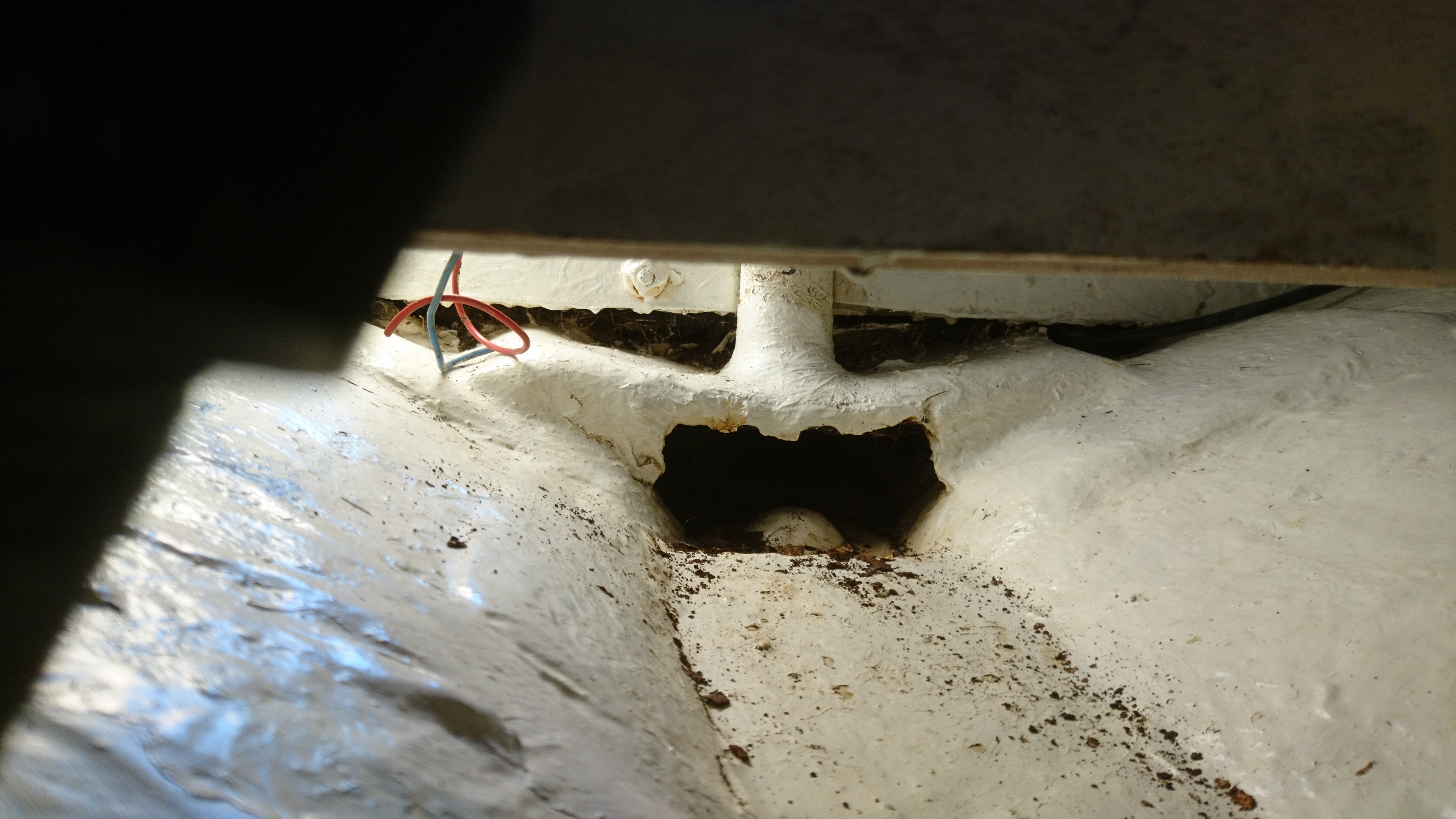
The little pile of rust immediately underneath is a dead giveaway there’s trouble afoot.

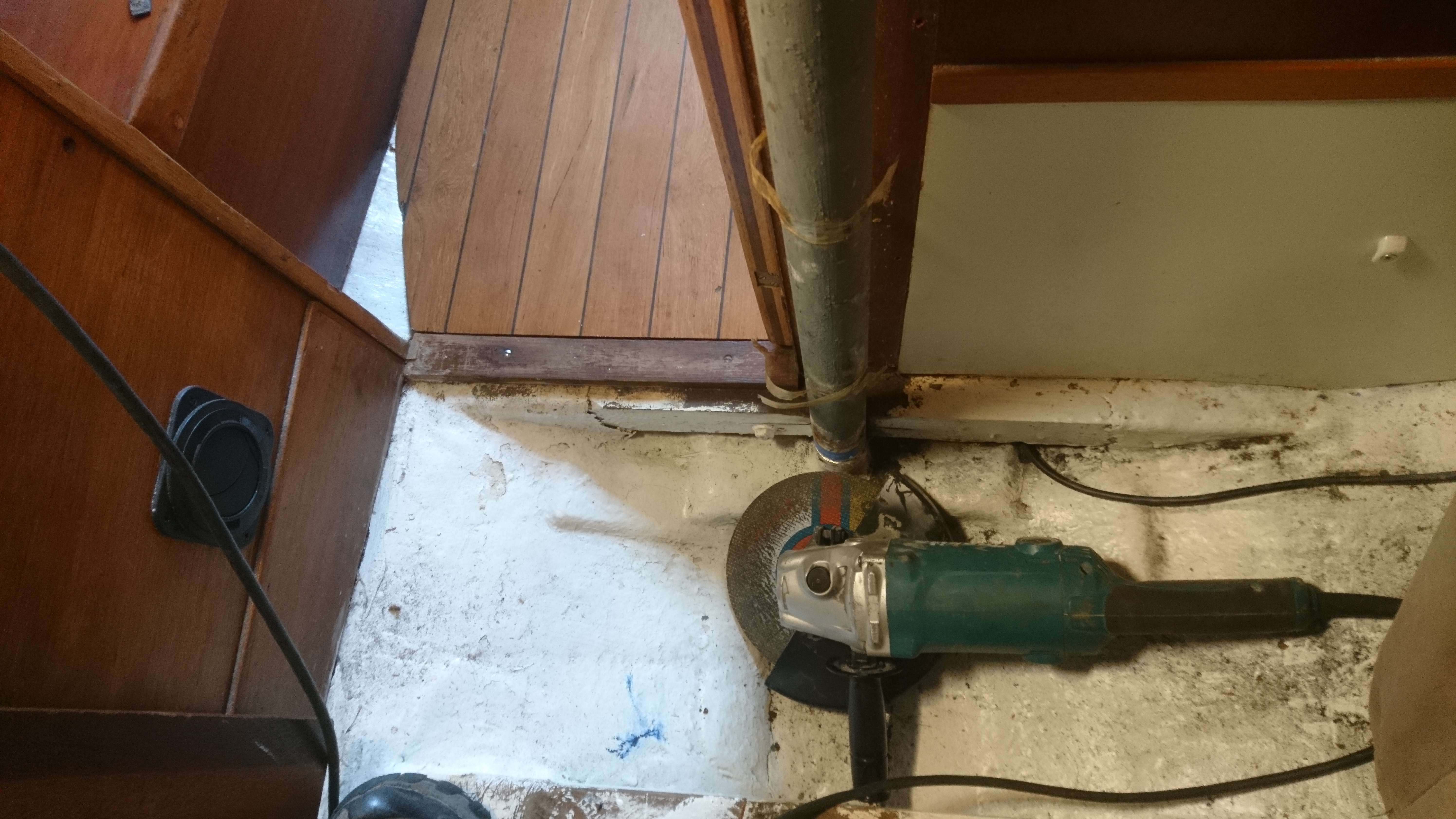
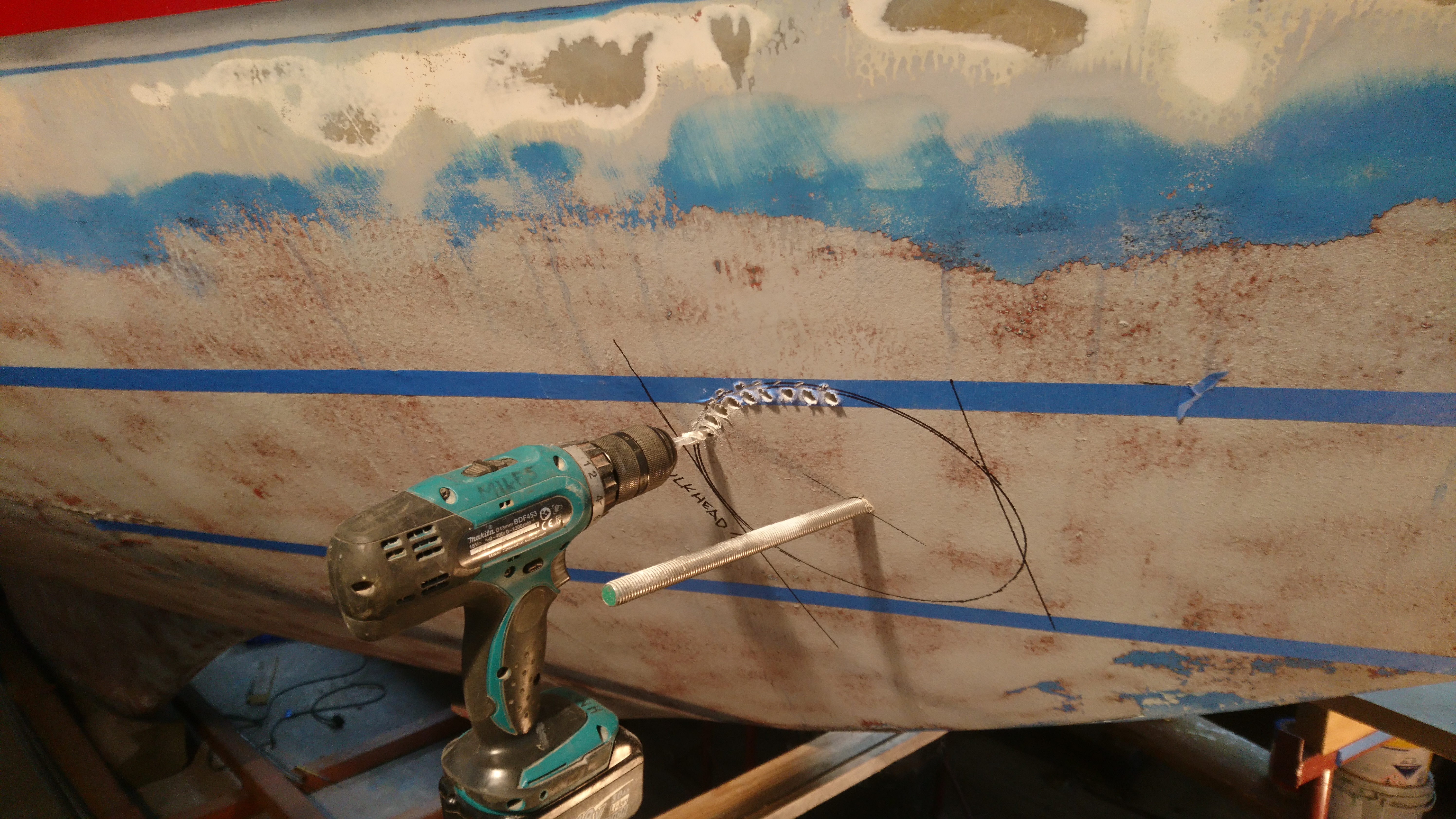
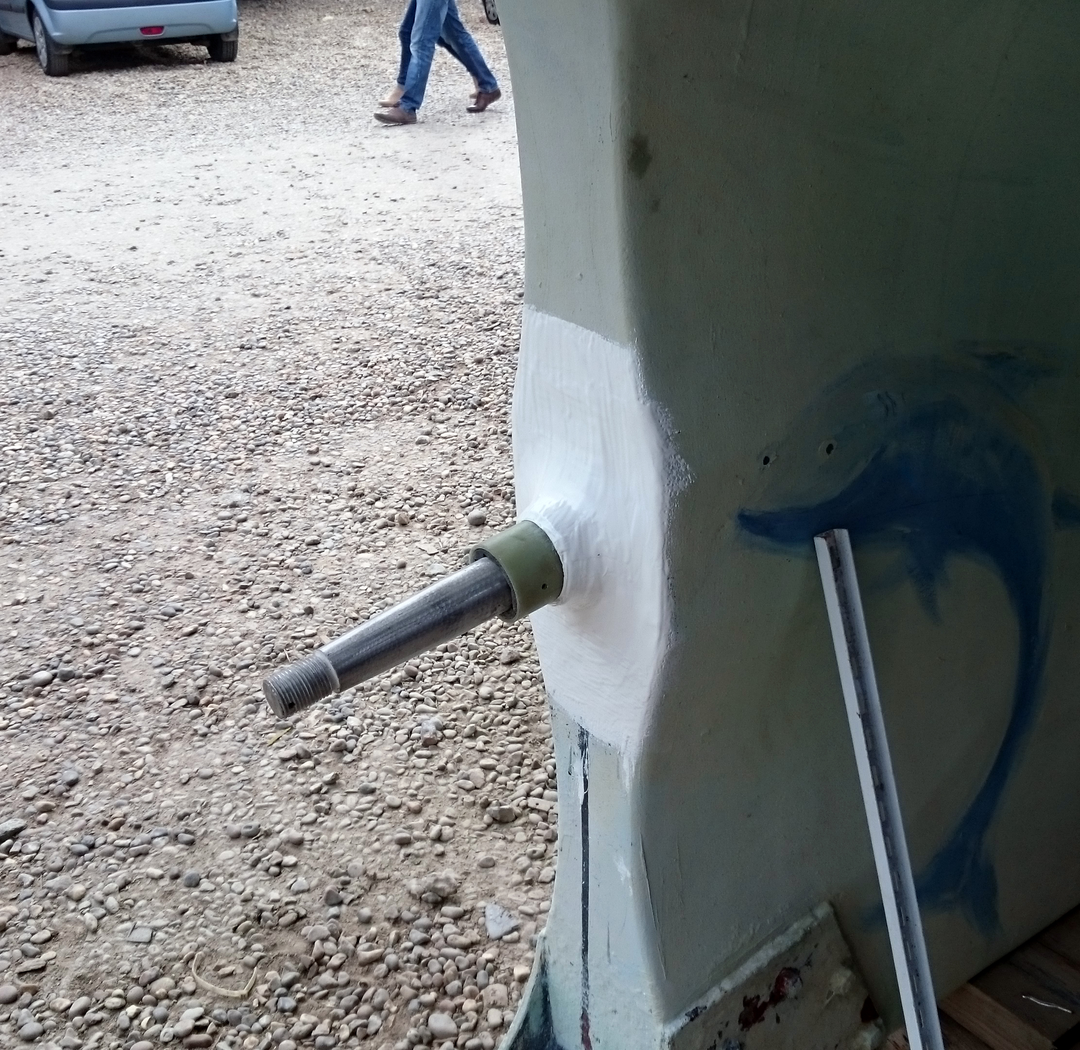
So the first job is to let all the rig tension off and then cut away the base of the pole

By | 2017-06-04T18:22:26+01:00 May 11th, 2017|Uncategorised|Comments Off on Compression Post

Bow thruster

We’re not great fans of Bow thrusters here on the river.
You simply don’t need them when you’ve got a 2knt flow one way or the other to work with.
So when we hear that unmistakable sound we usually drop tools and watch whoever this latest visitor is, trying to move his vessel sideways into the tide with often hilarious effect.
That said in static water, like a locked marina we accept that they are very handy.
A few years ago I spotted a scalloped bow thruster tube on a Southerly and thought, yeah that’s looks like a good idea.
I could see there would be a reduction in drag compared with the usual eyebrow and probably noise whilst sailing as well, especially when heeled.
So along came an opportunity to try out our own design.
We firstly looked into a retractable thruster as there’s no doubt that these have the least negative effect on performance. The issue is that many yachts simply don’t have the room or suitable layout to be able to install one plus they are not cheap.
So the decision was made to try out our design on a Southerly 38 and after the success of that we followed up with a slightly more technical version on an aluminum Ovni 38.
The performance loss when sailing on these two boats was negligible, maybe .2 knt compared to the usual ¾  to 1 knt we usually saw from the conventional installations with eyebrows.
Yes the installation is a lot more complicated and does require me to cut two dirty gashes down each side of your pride and joy but the reduction in drag and the resulting accidental increase in strength in this important pounding make it well worth it.
The length of the original scallop on the Southerly I saw was in my opinion a little too short.
I’ve always used a rule of thumb that an obstacle will cast a disturbance shadow of at least three times its size at the kinds of speed we sail at. So if I have a 200mm hole I need at least 600mm aft for the flow to settle down again.
One day when I’m rich I’ll do the CFD to back up the theory but at least the practice seems to back it up.

Before we start I should point out that there are lots of ways of doing the same thing, especially when it comes to working on boats.
So the methods I use are the methods I feel most comfortable with, given that it isn’t my boat and that if it goes wrong it’s going to be very expensive.
This pretty much follows for all of our work at the yard.
We’re generally risk averse as failure in part or total is not a good long term business strategy especially as largely our business is generated by word of mouth recommendation and returning happy customers.
So the following is a run of the mill yard job but in isolation it is pretty major surgery with drastic consequences if it fails.
You have been warned.

For a bow thruster to work effectively it needs to be positioned as far forward as possible but needs to be a tube diameter below the waterline so as not to cavitate in use.
Then we come up against the physical limits in terms of available space for the tube and the motor and the necessary access so that the tube can be safely glassed to the hull.
Looking at the hull from the inside can give you a good idea of a suitable location but its often tricky to identify that location from the outside.
So you need to find a datum point that can be viewed from both inside and out that is as close as possible to the proposed location.
Lucky for us this Nicholson 39 has a through hull depth/speed transducer on the center line around 2 feet aft of the proposed thruster location.
So from this point it was relatively easy to project lines marking the bulkhead position (adding a bit for luck) on the outside of the hull.

Once the center point of the tube is found a small hole is drilled through both sides and a 5mm dia rod is inserted through to check alignment both inside and out.
When happy its time to open up this small hole out to 12mm which allows us to use a length of m12 threaded bar as the center line rod that won’t bend during the marking process.

We have a special tool for marking the hole but as with most things in a busy yard its gone walkies so I made a very quick and easy tool which actually worked just as well as the “Special one”.

I still prefer to stitch drill rather than use a 200mm hole cutter.
Yes it takes longer but it is far more controllable.
Leaving the center line bar in place gives you a guide so you drill at the correct angle.
I use a 8mm drill for the stitch holes and usually have to sharpen the drill bit a few times on a bench grinder by the end.

Once the holes have been drilled I use a jigsaw to cut from hole to hole.
Unlocking and loosening the base screw on the jigsaw allows you to keep the blade at the correct angle.
Don’t be tempted to try and cut the entire hole with a jigsaw unless you are 100% confident that you won’t wander off line.
I don’t have such a level of confidence so I stick to stitch drilling.

With the centers removed its an easy if dusty job of removing the rough drill slots using a sanding drum with 40 or 60grit paper.

A few words on the dust.
It’s particularly pernicious, intrusive. smelly and definitely anti social stuff.
You need a FFP3 mask and a disposable hooded overall over your overall.
Inside you need remove everything from the forward cabin and seal the doors.
Even then you will find evidence you missed a bit.
Outside the hull its much harder to control so its damage limitation, we evacuate that shed and the guys move to one of the others, grumbling under their breath until I’ve finished and fired up the vacuum.

Holes in boats are never a good thing.
Huge great holes in a pounding area of the hull are even less good idea.
So I employ a belt and braces approach and ensure I bond the tube externally as well as internally.
To do this I chamfer the outside of the holes so I can get a good 15mm glass thickness around the external joint.
Initially I cut back 50 or 60mm back from the main hole but this will be increased when I get to glassing.

Whilst the nominal dia of the tube is 200mm, because its cut at an angle the largest distance from one edge to the other is 270mm.
So the proposed scallops will need to start at 270mm wide and extend at least 700mm aft.
Looking from the front I can see I’ll need a scallop depth of 45mm.
The next task is to make a mold for the two scallops.

The initial layup of the scallops needn’t be too thick as additional layers will be added later when bonding it to the hull for both inside and out.
The first scallop hole cut into the hull is always a little scary as the hole is BIG and you need to be sure you have it in the right place which on a boat with constant curves is not easy though your eye is pretty good at alignment and often better than a tape measure as many hulls are not as symmetrical as you might think.

Grinding this scallop hole produces prodigious amounts of dust, so sheeting off the area is important and covering every inch of your body in protective gear, vital.
Eventually its a case of grind a bit, test dry fit, grind a bit more, until it all sits nicely together.

Whilst in the early stages we assessed whether there would be sufficient access to glass the tube and the scallop to the inside of the hull, now we have a dry fit you need to look more closely at exactly how you propose to glass it all in.
Obviously the underside of the tube and scallop will be the hardest to get too so I grabbed a brush and roller and ran a test to check I could get to all the joints.
As a result a little more bulkhead had to be cut out of the way and will be replaced later.

When happy with the hole on one side its an easy process to make a cardboard template to mark out the other side.
Then its a case of rinse and repeat.

Moving inside the worst job is grinding back the interior glass to provide a good key.
I aim for a border of clean glass layup at least 6 to 8 inches, followed by scrupulous cleaning of the dust with a high power vac, then a good blast with an airline, finishing off with a thorough wipe down with acetone.
The bonding area of the tube and the scallops get the same treatment before final positioning.

We are using polyester resin and layup as opposed to epoxy.
It’s very much cheaper and faster to layup and the thickness of layup will be immensely strong, the additional weight not being a factor on this boat.
The tube and Scallops are bonded into place using bonding paste, which is the same stuff most decks are bonded to the hull with these days.
The layup is time consuming, especially the tricky glassing under the tube.
I use a couple of mirrors and a long handled brush and roller.
It takes a bit of practice working upside down using a mirror but its obviously imperative that you get a good, consolidated layup.

When glassing the tube it’s worth spending time cutting the glass for each side before hand and laying them on top of each other in order of use.
This is an easy way of ensuring you get an even number of layers on each side as its very easy to lose track of how many you have done.
Due to the shapes and angles involved you have to use short pieces of cloth around a foot long and a maximum of 150 wide.

The first layers are chopped strand as they provide a better grip to the old glass than woven cloth.
Then I move onto 100mm wide biaxial tape and then 450g 150mm wide biaxial tape.

A top tip here is to wet out the glass on a scrap strip of hardboard first and then carefully transfer it to the tube/hull joint which ensures you don’t get any dry areas, at the same time its a lot easier to wet out using the minimum amount of resin which is just as important as too little.
A very common fault of the amateur laminator is using too much resin which will result in a brittle and less strong laminate.
It takes me at least three full days to get all the laminating done, its not something that cannot be rushed.
One of the trickiest jobs is locating the position of the gearbox in the tube.
You only need to be a gnats out and the prop will foul on the tube.
So adding a few strips of masking tape you can mark up the position accurately taking into account that for the prop to be in the center of the tube the motor has to be offset to one side or the other.

Lewmar (bless them) provide a template page in the installation manual to aid fitting. They even call the page “Cutting Templates”.
They then ruin all this work by watermarking the page “Not to scale”! and sure enough they are not to scale but the really frustrating thing is not by very much at all.
Completely bonkers.
So ignoring the manual I use the actual saddle as a template and mark and cutout the require holes.

The owner had decided to locate the thruster battery next to the tube so once the tube and scallops had been glassed, and the gearbox and saddle position settled, the next job is to glass in some shelf supports and then make a template for the shelf.
For this job, strips of gash plywood cut into strips and a glue gun are your friends, a fast and accurate way to template any panel on a boat.
The shelf is made from 19mm marine play and is glass sheathed.
To finish I applied a few coats of gel coat and topped it off with gel coat with added wax in styrene, otherwise know as flowcoat or topcoat gel coat.

Moving back outside the tube and scallops are glassed to the hull and are then made fair.
Scribbling in marker pen is a great way to see highs and lows when sanding and filling.
Whilst the boat was in the shed we had also resprayed the hull and grit blasted the underwater sections and applied four coats of epoxy, then primer then anti-foul.
A point of note here is that epoxy is not as good at bonding to new polyester as it is with old cured grp. The styrene in the layup takes time to leach out during the curing process, (it can take months to fully cure) and this can sometimes effect the bonding ability of the epoxy coating in direct contact. You can speed up the process by cooking the laminate but this is obviously not an option.
So we made sure that the new glass is well keyed and primed and we’ll check on the condition at the end of the season.

The test running will have to wait as the owner wants to carry out the wiring himself which will save him a few pennies, hopefully.
If not, I’ll be running another article shortly on rewiring a partially wired bow thruster.

The tape line marks a tube diameter below the waterline.
Top edge of the tape sets the height of the top of the tube.

Using the Log skin fitting as a datum point that we can identify both inside and outside the hull we can then check the location of bulkheads and knees.
From this we can choose the best place for the tube.

Drill a 6mm hole through both sides and then check inside to see if they are level and are equidistant from the datum point.

Complication on this boat was that there was a sub floor glassed in above the pilot holes.

This section will be cut out and removed.

Once happy with the position of the center holes we drill out the holes to 12mm and insert a length of M12 bar through the hull.
This allows us another visual check on alignment and gives us a new datum to draw our cut out  sections.

I made a simple tool to mark the tube entry using a piece of copper pipe, scrap wood, a pen and masking tape.
The tube slides in and out on the threaded bar and makes life a whole lot easier to mark what is actually quite a complicated shape.

We could have used a big hole cutter but in my experience its fraught as it tends to snag and tries to snap your wrists off.
So I opt for stitch drilling which I find far more controllable.

This looks like the center is not er, central.
It is, have faith.

I use a jigsaw to cut between the drilled holes, making sure the base of the jigsaw is unlocked so that as you cut round you can keep the blade at the right angle

After a couple of hours we have two dirty great holes in a customers boat and square on they even look round.

The sections that were cut out show just how strange a hole for a perfectly round tube can be.

I use a large dia foam sanding drum with 40 grit paper to fair the hole out to the marked line.

Port almost fair and starboard still rough but from this angle you can see the position of the tube entries are spot on.

Though the Stb hole appears to be slightly fwd when looked above.
(unless the bulkhead is on the wonk.)

The view through the fwd hatch shows that the tube cannot be any further aft and the motor will have to positioned forward of the tube.

Whilst the tube will be glassed internally to the hull, I like to also glass in externally as well.
So I mark out a 50mm guide which I chamfer and in the process fill shed 2 with dust, which gets everywhere.

Once the chamfer is done it gives me a good 20mm depth of glass externally.

After a little trimming the tube can be test fitted.

Clearance round the tube is around 2mm.

Inside all looks nice and square.

When happy its time to mark the tube for cutting.
I leave around 20mm surplus which I can grind back later after the glassing is done.

With conventional fitting we’d be into glassing but for us its time to look at the scallops.

Making a quick mold for the scallops using some gash bits of Kingspan insulation board.

The profile was cut on the wood sections on a bandsaw and then with the blocks of insulation, glued in place with a glue gun.

The foam is easy to cut away with a saw blade and a length of 40 grit sandpaper stuck to length of plywood with double sided tape.

This mold is only wanted to make two scallops so I’ve cheated by laying a sheet of mylar over the foam and stuck down with double sided tape.
I applied one coat of slipwax polish and it is now ready for Gelcoat.

4 coats of gelcoat were applied in between doing other jobs. Roughly one coat every hour with the aid of an Infra Red lamp.

This layup will eventually be quite heavy once glassed into the hull.
Initially though I used 2 layers of 450g csm, 3 layers of 300g biaxial cloth, 2 layers of 500g 150mm wide biaxial tape.

Marking up the cut-out for the scallop.

Check that the owner is not about and then cut a huge hole in the side of the boat.

Offering up one of the scallops, the hole is marked and fettled to get a good dry fit.

The tube is inserted, marked and cut to profile.

A visual check from the front shows that the cut out could have been a little bigger at the bottom.
This would mean asymmetric molds rather than the symmetrical one for both.

There’s still an hour or so worth of adjustments using a grinder and flap disc to get a nice joint.

From inside looking down you can see the junction between the tube and the scallop on the port side.
Starboard side is yet to be cut out.

Dry fit of Port side scallop as viewed in the port side bunk locker.

Dry fit of Port side scallop inside the port side bunk locker looking forward.

Using the port side hole as a guide we make a template for the starboard side which speeds the cutting out process up considerably.

Wet out the glass on a piece of scrap ply before putting it position.

Initial layers are 450gm Chopped Strand as I find it bonds better than cloth.
Pre-wetting out helps getting into tight areas.

Tube partly glassed in using 450g biaxial tape and cloth.

The access holes in the bulkhead can now be filled with 19mm ply and then sheaved to seal the locker once again.

Scallop finished and ready for a gel wash.

Outside the scallop joint is glassed to the hull.

Once glassing is finished its time to fair in.

Scribbling with a marker pen and then sanding is a great way to find highs and lows when trying to fair the hull.

This job eats 40 grit sandpaper discs, you can easily use a full box of 50 on a boat of this size.

Testing the position of the saddle and motor prior to marking and drill the gearbox holes.

Using tape on the tube makes it easier to see the positional marks before drilling.

Honestly, whats the point of a Template page printed “not to scale”?

Template made (to 1:1  scale) for the battery shelf.

Shelf supports glassed in and everything coated with gel coat.

Outside the fairing complete and being primed.

Motor and shelf fitted.

Internally the scallops are hardly noticeable.

By | 2019-10-06T00:45:47+01:00 April 3rd, 2017|Uncategorised|Comments Off on Bow thruster

Holding tank

Based at Southwold on the East Coast we generally have two choices when we leave the harbour.
Turn right or head straight across. (us locals try and avoid turning left!)
Heading straight across means that in 12 to 14 hours we’ll be in Dutch or Belgian waters and among the myriad of required items we should have on board or fitted is a holding tank, especially if we want to visit the inland waterways.
The trouble is many of our boats produced in the 80’s and 90’s really didn’t take this into account so it can be quite difficult to work out where to put an additional 100+ litre tank.
Most of the obvious places to fit a tank already have a tank so it means we have to get a bit creative.
Lucky for us Tek-Tanks  allows us to be creative and will build a tank to fit some really weird shapes.
I’m sure there are other tank builders that can do this as well but I’ll let you into a yard secret.  We go with what we know works for us. It’s always a risk going with another company as we rely so much on word of mouth that we cannot afford to fit something that fails, as it firstly reflects badly on us from the customers perspective, it will cost us money to fix which invariably will wipe out any margin we had built into the job and the delay will also affect the next jobs, with manpower, shed space availability etc
So when you find a system that works you stick with it.
Anyway an Oyster 406 came in for a new Beta engine, a new electric loo and a holding tank.
Whilst our engineering boys set about the “how do we get the old engine out?” issue, I got on with measuring the total cupboard space above and behind the fwd Heads and as long as the owners could find a new location for their tooth brushes and shampoo I believed I could get a 110 lt tank in there.
Yes it was a strange shape but nothing out of the ordinary for Tek-Tanks who whilst not very cheap have come up trumps every time I’ve set them a challenge.
It would require a little bit of surgery to the boat interior and also some thought to ensure there is future access.
Original builders/designers tend not to lose too much sleep over ensuring access to things that could need maintenance in the future, with quite large areas of boat that are simply inaccessible.
Being sailors and owners ourselves coupled with the frustration of getting to fittings, bolts, pipes, cables, not to mention areas of hull that you need to get access to in case some numpty t-bones you in a marina, we like to enable that whatever we put in, can be removed and attempt to provide access  to previously no go areas.
We could have totally filled up the available space and found another 30 litres of tank space but access would have been made much harder to the top fittings such as the air filter/breather, flush out and level sender, so practicality won the day.
The heads molding is quite tight to the hull so the skin fittings are forward of the main bulkhead in the forward cabin.
Changing fittings including toilets will always result in redundant and unsightly holes so this dictated the location of the access hatch and this in turn finalised the position of the diverter valve.
The electric loo switches were mounted through 5mm white plastic sheet glued to the side of the sink cabinet, again covering a number of redundant holes.
We could have glassed and re gelcoated but the extra expense was viewed as being unnecessary.
The one issue I have with electric loos are they are so incredibly noisy and Jabsco even has the temerity to call it the quiet flush.
There should be a little flag raised when you use it in a marina saying “Yes we have a holding tank”.
That said it works well and based on the lack of complaints from customers they seem very reliable.
This is the first time I’ve used the Jabsco diverter valve and I’m hoping it proves reliable as fitting it was a breeze especially as the outlets are movable and allow many angles for the 38mm pipework.

On testing the loo and inlet pumps were more than adequate to discharge into the tank and with the diverter valve set to empty the tank level dropped like a stone.
An initial worry was about having 100kg of extra weight up high and out on one side but once the boat was on the water it made very little  difference visually and of course, once offshore the tank could be emptied anyway.
The owners report back was very positive and apparently the noisy loo issue is not as bad as I feared as it takes such a short time to flush.

With the locker doors, a shelf and a dividing panel removed we found we could squeez a 100 liter tank inside.

However to get it in we would have to cut away some of the fibreglass above and to one side of the locker.

I sent Tek Tanks a rough drawing and they send me a proper one back for approval before manufacture.

A couple of weeks later we had a tank ready for a test fit, time to test whether I can measure odd shapes correctly.
Thankfully I did.

With the tank in place we ensured there was space above to allow a tank level sender unit and breather filter and allow access so that the carbon cartridge can be changed. The flush and pump out fittings and pipework are hidden behind the fibreglass panel on the left but can be reached over the op of the tank if needed.

Below the tank we fitted a hatch cover to give access to the bottom of the tank and to the three way Jabsco diverter valve.

We also took the opportunity to fit a new electric loo.

The trim and doors back on ensuring that everything can be dismantled to get full access to the tank in the future.

The owners will have to find a new place for their tooth brushes.

The hatch above the loo gives access to all the pipework and the excellent Jabsco three way valve which has clever adjustable hose fittings that accommodate irregular pipe angles.

Apart from the extra little bits of trim and the viable fasteners to enable easy access the look of the heads is largely the same as before.

By | 2019-10-06T01:01:45+01:00 March 30th, 2017|Uncategorised|Comments Off on Holding tank

Deadwood fairing

Small project to fair in the deadwood on a Colvic Watson and installation of a smaller prop

Updated – 20/3/17

We recently carried out an engine change on a Colvic Watson. All went well, however the original huge prop has now become a little too huge when under power.
In gear at tick over the North Sea visibly increases speed through the Dover straits and the new engine would only rev to around 1500.
So we need to reduce size of the prop and possibly increase the pitch.
On the positive side reducing the size will reduce sailing drag but there isn’t enough in the owners budget to stretch for a feathering or folding prop.
There’s no doubt that a big three bladed prop causes drag, especially one coupled to a hydraulic gearbox that cannot be left to freewheel and a smaller prop will cause less drag but the danger of reducing the prop size on this design is that so much of the prop is hidden in the shadow of the keel. 
We could keep the prop the same size and just increase the pitch but the owners like to sail so improving efficiency by reducing drag is the best option and given the budget constraints a smaller prop is the way to go.
So the task is to improve the flow round the back of the keel and give the smaller prop half a chance and at the same time it will vastly improve the flow over the rudder.

The initial plan of a short fairing just didn’t look or feel right to me.
My rule of thumb is to look at an underwater obstruction and times the size by 3 to gain an idea of when the flow might start to get itself sorted out.
So a 5″ wide trailing edge will be casting a shadow at least 15″ aft.
There’s no way I can get 15″ of fairing so I’m just working on getting as much as I can.
A few more chunks of celotex and a glue gun gave me something to work with to get a reasonable shape.
I shaped it by eye rather than spending a lot of time making templates which kept the costs down.
A good 10″ of existing keel was ground back to provide a good key and anchor for the fairing.
The keel and foam was then tied together with a four layers of 450g chopped strand mat and polyester resin.
Three layers of gelcoat was then applied and a final coat of gelcoat with added Wax in Styrene which acts as a top coat.

Whilst a great gelcoat finish isn’t really required in an area soon to be covered in layers of primer and antifoul I advise you still apply multiple thin layers of gelcoat rather than slapping on a thick coat.
The issue is that during the mixing phase you will inevitably introduce air into the mix.
Applying the gelcoat in a thick layer will trap these tiny air bubbles which can make the gelcoat porous and if you cut back to get a really shiny finish you will get tens of tiny holes that are impossible to fill. Cutting back more just exposes more holes and so on.

Gelcoat will not cure in air, it gels and stays sticky.
When applied to a mold and then glassed over the air is eliminated and the gelcoat will set hard.
So when applying on top of glass without a mold we need to eliminate the air somehow.
To do this we add wax in styrene in roughly the same quantity as you add the catalyst.
During the curing process the wax comes to the surface effectively sealing the gelcoat from the air and allowing the gelcoat to set hard.
It should be noted that if you need to add any additional layers of gelcoat you will need to remove this wax by keying well with wet and dry sand paper or similar.

Once completed our sea trail proved we had chosen the right size prop as the boat top speed is unchanged but the engine now revs to 2500.
The biggest change was at slow speeds where the slow handling has been transformed for the better.
We await reports back from the owners on sailing performance.
Next time she’s out of the water I need to convince the owners that the barn door they use for steering needs some matching hydrodynamic help.


The trailing edge of the Colvic Watson is not the mostt hydro dynamically friendly design.

The direct shadow caused by the trailing edge of the keel over the old, huge prop.
The new smaller prop would struggle.

Initial plan was for a small fairing using a foam core.

I decided that it simply wasn’t enough so the fairing grew.

and grew…..

Final shape with prop temporarily fitted to check clearance ready for gelcoat.

After three coats of gelcoat and one coat of topcoat or flowcoat gelcoat. (essentially gelcoat with added wax)

A coat of International Primocon and then a couple of coats of Seajet antifoul, shes ready for the water.

By | 2017-05-03T23:24:23+01:00 March 20th, 2017|Uncategorised|Comments Off on Deadwood fairing

Dodgy knees and soggy decks

Job finished. Update – 03/5/17


Looking around the yard, I notice that of the nine boats being worked on today, the youngest boat is over 10 years old and the oldest is 80 years old.
The majority are between 15 and 30 years old, and 28ft and 60ft in length. Predictably the three oldest are wooden, the five grp boats are all in the 18-30 club and youngest of our current crop is a 57ft’ foot aluminium, iceberg chasing, ketch.
Most are in the yard for several reasons: three are having new engines, three are having new decks, two are having new chain plate knees  and bulkheads, two are having new ? (water, diesel?) tanks,  two are undergoing full restoration and one has finished her full restoration and is now floating and having the finishing touches made before returning to her owner.

So many times the cause of a restoration starts with leaking decks. Modern boats suffer the same fate as well. Two boats currently  in for new knees and chain plates were also because of leaking decks, a  57ft aluminium ketch is in because its teak deck had lifted and the aft deck of a Colvic Watson is undergoing strengthening surgery and curing some, you guessed it, leaks in the deck.

I’d argue that fresh water is a far bigger evil than the salty stuff, in terms of keeping you afloat.

If you don’t keep a close eye on through deck fittings by the time you see evidence the damage has already started.
The biggest culprits are window frames. genoa tracks, stanchion bases and through deck chain plates.
The first place for water to explore once past failed sealant is the deck core.
The core is usually balsa, foam or plywood or a mixture.
If its wood its obvious what will happen over time, with foam you might be lucky although water will encourage delimination of the deck upper and/or lower skin from the core and slowly spread.
The next place for water to reach will be the back of headlining or trim that covers the entry point.
The water can travel a long way before emerging as a drip usually on the back of your neck whilst trying to read a chart at the nav station.
The danger is that in the case of chain plates, water will get between the chain plate and the knee or bulkhead it’s attached to.
It will then travel along the bolts and start to soak the wood, that is usually encapsulated in grp, which now essentially turns into an unhelpful bucket.
The wood rots and the chain plate will lift, usually raising the deck in the area before eventually failing resulting in a lost rig or worse.
Obviously this wont happen over night but most of us are sailing in boats over 10 years old and that’s enough time for this to become an issue.
We have two boats in their 20’s at the yard with this problem, severe enough to mean cutting out the old knees and replacing them.

If you’re worried but can’t see any evidence see if you can get hold of a moisture meter which often gives you a heads up. 
If you suspect water has got in then you’ll need to dig further.
We remove the chain plates which allowed us to have a good poke at the core with something pokey.
On the Pasport 40 the core was pretty good, damp but still firm with no obvious signs of damage.
On the moody however the plywood core was wet and rotten and needed to be cut out around the chain plate slot and the old cover plate fixing screw holes, it also extended aft and outward a few inches from the slot which follows the fall of the deck.
Down below it was a different story on the Passport 40 with the inside of the Knees saturated, the wood turned to mush.
Water had even got between the knee laminate and the hull and on removal we saw at least a couple of cupfuls of brown water drain down into the bilge.
On the moody we drilled out a core from the knee around 3ft below the deck.
The moisture meter was not happy even three feet down from the entry point and whilst not soaking it was bad enough to condemn the knees especially considering the poor design of the chain plates.

Repairing the deck on the Moody could have been done from inside but given we were going to redesign the chainplate and incorporate a sealed top plate which would cover the repair, it was decided to repair from the top which is a whole lot easier to do saving time and money.
So first we cut away the top deck laminate to gain access to the core.
The best tool for this and one of the most useful tools in the yard is the Oscillating Multi-tool in both 240v and 18v battery versions.
The blades are horrendously expensive but if you’re paying £30 an hour for me to do this and it takes less than half the time than using a chisel then it makes sense.

Once the wet core is removed and you’re back to solid wood then its time for a heat lamp for a day or so to get the moisture content down and give the epoxy half a chance to work its magic.
When dry, we tape up the chain plate slot below decks and coat the exposed edge of the core with warmed up epoxy.
Warming thins out the epoxy and it will soak in better but shortens working time so keep the batches small.
Before this has time to go off we build back up to original deck level with epoxy and glass cloth.
I used a couple of layers of powder bound csm (Powder bound csm is specifically designed for use with epoxy you should never use normal emulsion bound csm with epoxy) and then layers of 300gm and 450gm biaxial cloth.
I like to use the csm (chopped strand mat) initially as I believe I get a better initial bond and its easier to manipulate to ensure I get coverage over the edge of the core material.

Below decks things are about to get really very messy.
Cutting old grp is bad enough and the knees will come off pretty easily with the multi-tool.
Grinding back to good clean laminate so we have something nice to epoxy too is a different matter.
The dust gets everywhere and I mean everywhere.
Plastic sheets and masking tape covering everything you can see, floor, roof, bunks everything and even then there will be a dusting of white powder in the aft cabin locker under the bed!
We normally encourage owners to come in help and especially carry out some of the mundane tasks as it saves them money.
I’m not sure I’d like to pay someone to drive a vacuum cleaner at yard rates but sometimes there is no choice.
Once the inside of the hull is nicely keyed and most of the dust is sucked away we can bond in the new plywood knees.
We use the old knees as patterns and bond in the new ones on thickened West epoxy using 404 high density filler to bed on and 406 colloidal silica for filleting.
Once this has gone off we abrade the fillet to remove any blush and round off the inside edge of the knee as glass cloth does not like going round sharp corners, then we can start to sheath the knee.
This soaks up time and it can take a full day to glass in a full height knee.
Its important that you try and get it all done in one go so you don’t have to go through the removal of the amine blush which happens during the epoxy curing process.
You could use a product called peel ply which avoids this issue though its not cheap and for intricate shapes can be a pain to use.
Another issue with epoxy is unlike polyester resin you can’t afford to mix up too much resin at a time for fear of it exotherming (going off) especially if you warm the epoxy to reduce its viscosity to aid wetting out the glass.
So I tend to mix up a maximum of 8 pumps at a time.
Coating the whole area first I lay up two layers of 250g powder bound csm followed by 4 layers of 300g biaxial cloth.
That essentially seals and sheaths the knee.
I then start adding the tabling which is the main laminate that joins the hull to the knee.
Using lengths of 150mm wide 450g biaxial cloth I lay up 6 layers starting with around 125mm on the hull and 25mm on the knee and then overlapping by around 25mm each time, ending up with 125mm on the knee and 25mm on the hull.
The area that will take the loading from the chain plate gets additional layers, taking into account the direction of stress.

Once cured the position of the chain plate bolts can be marked.
Before finalising the positions of the bolts check that there will be access when the interior woodwork is put back in place so that you can carry out regular inspection and future re-sealing if required.
Ensure that if the knees are used in the mounting of the interior trim at any holes made by screws are suitably sealed.
Once happy, core drill the bolt positions out to 25mm diameter.
You can check each core plug to check laminate thickness and see how well each has bonded and whether I’m any good at laminating.
Tape up on side of each hole and coat the bare wood with neat epoxy followed by filling each hole carefully with a thick epoxy high density mix. I use a syringe for this usually but you need to ensure all the air escapes otherwise you can get a void which will need to filled afterwards.
When this has set we can re-drill the final bolt holes, in this case at 12mm.
The chain plates can now be fitted, either bedded down on a suitable sealant or a epoxy silica mix.
These repairs should be good for another 25 years at least, though fresh water has a horrible way of finding its way in.
So don’t ignore the soggy tide tables, investigate why before it attacks something else.

Typical modern deck with multiple through deck fittings.

Removal of the fitting will allow access so the immediate area of the core can be inspected.

After identifying water ingress the choice is to either cut it out below decks or in this case, above decks.

Deck skin removed on Passport 40. The dark wood is wet the rest is damp. Note the poorly cut out slots for the chain plates by the original builder.

The damaged core can be removed without damage to the inner skin.
Assessment can then be made to the extent of the core damage.

Top layer and soggy core removed

Passport 40, chain plate sections removed ready for drying out and filling/glassing with Epoxy

Seal the dry core edge with neat epoxy, then fill with thickened epoxy if necessary before laying up with epoxy/glass.

Continue to add glass until just proud of the deck and sand back flush. Be careful not to sand away any non-slip from the surrounding area.

After time, water leaking into a knee will turn the wood into mush leaving just the outer shell which has little shear strength and certainly will not stand up to significant rig loads.

Down below discoloration in the knees laminate and more obvious water stains from the chain plate bolts are a sure sign of trouble.

To track the extent of any damage a core can be drilled out lower down the knee and inspected using a moisture meter if no obvious signs exist.

If the damage is irreparable there’s no option other than to cut the old knees out.

With the knee removed you can see if any other horrors lurk in the background.

Can’t avoid this, it has to be done. grinding and sanding the interior ready to take the new knees.
The dust this creates in truly unbelievable, but you must not skip this task.

New plywood knees are bonded to the hull on thickened epoxy.

After 2 layers of 300g powder bound csm the first of 4 layers of 300g bi-axial cloth can be applied.

6 staggered layers of 450g bi-axial tape on each side of the knee.

High stress areas have additional layers of 450g bi-axial cloth. 

TOP TIP – If you don’t have time to layup in one day use a layer of peel ply.
When you are ready to complete simply peel off the the peel ply and the surface will be ready for the next layers.

Once mounting bolt locations are identified, 25mm cores are drilled out.

The cores can be inspected for laminate thickness and consolidation.

The bare ply in the cored holes needs to be coated with epoxy.

The cores are then filled with thickened epoxy.

The m12 final holes for the chain plate will have at least 10mm of epoxy silica colloidal around the bolt.

The cabinets were modified to enable easy access to chain plates in future.

Matching wooden blanking plates will be inserted and screwed in place.

With easy access it will be easy to monitor any water ingress in future.

By | 2017-05-03T22:58:36+01:00 March 7th, 2017|Uncategorised|Comments Off on Dodgy knees and soggy decks

Shroud Covers

I really don’t like shroud covers.
Yes they look smart and I can kind of see that they might reduce wear on a foresail but almost every time I’m called to de-rig a yacht fitted with them the condition of the wire and turnbuckles is almost always in worse condition than shrouds that have been left uncovered.

By | 2017-02-11T01:07:34+00:00 February 9th, 2017|Uncategorised|Comments Off on Shroud Covers

Electronics

We’re lucky here at the boatyard as most of us love our sailing and own and sail our own boats.
In the course of our job we also deliver and move customers boats about and so we get chance to experience a wide range of gear, the good the bad and down right dangerous.
This in turn helps us when asked “what do you recommend”
That is until it gets to sailing Electronics.
Its almost a full time job keeping up with the latest and greatest sailing electronics from the main manufacturers.
Reading the blurb they all make it seem so easy but from an installers point of view the opposite is often true.
Running cables sounds easy but in some boats its a nightmare.
Yachts with wheels and binnacles have just enough room to run the original wiring but no way can you run extra’s up there and now we have fancy cables with molded plugs which won’t easily mouse down awkward holes so you end up having to cut and reconnect and some of the plugs themselves are just plain poor.

By | 2017-02-24T22:58:44+00:00 January 24th, 2017|Uncategorised|Comments Off on Electronics

Chain Plates

Complete – updated 7/3/17

In my dim and distant past I spent a number of years in manufacturing high end sports cars and I remember that there was only cursory notice taken when considering how easy it was going to be to maintain aspects of the car in the future.
The object was to get the car out of the door and start on the next one.

Not so different with production built yachts as we in the yard discover almost on a daily basis.
Some of the design and build decisions hidden away under spray lacquered veneers and flashy trim really smack of the same get it out of the door quick so we can build another.

Among my current grumbles is the poor design of through deck chain plates on modern-ish grp yachts.
To be fair this has been happening since the early 80’s but it’s not got any better.
I’m not sure whether this is an issue with the designer or a problem caused by the original build but either way it means trouble in 10 to 15 years or less if you’re not careful.

When we discover a through-deck chain plate leak it’s almost always between the vertical plate and the top cover plate. Sometimes there is localised moisture through the top plate fasteners which also allows movement, and then this allows water to get under the top plate.
This then travels down the inside of the plate into the knee, eventually rotting the encapsulated wood. Moisture also soaks the deck core and wicks between the core and the upper and lower grp laminates, which ultimately leads to delamination and significant weight gain.

Many people use an adhesive sealant which on the face of it seems like a great idea but I’d urge against it. The exposed sealant degrades in UV, even the ones that are supposed to be UV resistant will still degrade, just at a slower rate.
The end result is the same, a leak.
Small at first but constant over time with the added risk of getting creeping crevice corrosion in the chain plate itself.
A good friend of mine removed a 60mmx10mm backstay chain plate in two halves recently on a 40 footer due to crevice corrosion just where the plate entered the deck.

The adhesive sealant under the top cover not affected by the UV seals well but boy it makes life hard when you want to lift the plate and inspect.
So the chances are you don’t and so won’t notice that there’s already a leak you can’t see, yet.

Instead use a non adhesive flexible sealant such as Arbokol 1000 or butyl rubber.
These never “go off” and stay flexible and in my experience retain a seal for much longer.
However the beauty is that the top plate can be lifted easily, the old sealant cleaned away and the through deck slot can be inspected on a regular basis.

Our rule is if any fitting is bolted to or through the deck then there should be no need for an adhesive sealant.
If I don’t trust the fixings 100% then I may use an adhesive sealant, such as on window frames.
(Having seen windows blow out after crashing down a backless wave I don’t trust the interscrew’s on their own)

In the case of Chain plates there should be no requirement for an adhesive sealant, all that is required is a flexible sealant.
Looking at the various examples of soggy decks due to inadequate chain plate sealing the main cause is water running down the shrouds, over the bottle screw, toggle and vertically down the plate.
Next would be a small amount via the top plate fasteners and lastly under the deck plate.
Incidentally the often used shroud/bottle screw covers do not reduce the water by very much on 7/19 wire as the water follows the lay of the wire.
Also covering the bottle screw actually allows a build up of crud and green gunge which then leads to corrosion.

Our design for replacement through deck chain plates incorporates the top plate but it is seal welded to the main plate and has no visible fixing holes.
Instead it incorporates welded studs which are bolted through the deck.
There is at least 25mm from the outer edge to the nearest through deck hole.
This eliminates two of the three normal ways water gets in.
We have also incorporated a milled out groove under the top plates which will in effect provide a kind of o-ring seal.
The size of the top plates were designed to cover the deck repairs made due to the previously leaking fitting.
I decided on using an 8mm 316 plate instead of anything thinner to reduce the risk of deformation during the welding process to the 10mm main plate.

On this Moody 35, the original design is poor with the chain plate bolts way too close together which puts a lot of loading into a small area of the plywood knee.
Add water and a bit of time and its a recipe for disaster.
Our plate is significantly longer with well spaced mounting bolts.

Whilst we have our own welding equipment we use R&P Metalwork in Lowestoft for our critical Stainless Steel assemblies.
The manufacturing process is to firstly clamp the main plate plates into position down below, then slide the top plate into position and tack weld in place to get the precise deck angle.
Then the tacked assembly is taken away to be welded and polished before fitting using, in this case, Arbokol 1000. 

Moving below I find it strange that so many designers/builders make it so hard to gain access to the chain plates especially the area where the plate passes through the deck.
It was very high on the list of modifications I made to my own boat and I encourage others to work out a way of inspecting their rig chain plates at least every year, especially if you have a fractional rig which is subjected to higher static rig loads.

With the Moody we’ve spent some time making removable panels to enable access to all the bolts and to allow future inspections.
Originally it was a seriously major task to remove the internal woodwork to gain access.

The solution on the Passport 40 is a little different but again the original fault can be traced to the builders.
The main chain plate carries the cap and the intermediate shrouds.
This obviously gave the builder an issue as the designer had drawn that the chain plate should be mounted either side of the main saloon bulkhead.
So the builder decided to build a floating knee and clamp the twin plates either side of the knee.
Trouble is the lousy deck sealing system doubled the chances of water getting into the deck and then the knee, which it did.

We decided to follow the designers original intentions and mount the chain plate to the main bulkhead once we had beefed it up.
We redesigned the chain plate to incorporate a sealed top deck plate and both tangs using 10 x 90mm plate. 

With the solid top plate design it’s true that to inspect and reseal the plate it will have to be unbolted and lifted up.
However rigging up a couple of halyards, one side at a time, marking the bottle screw height before easing off, then  given reasonable access to the chain plate bolts, the chain plate can easily be lifted within an hour, cleaned resealed  and replaced, so long as you used a non adhesive sealant!

Typical 80' and 90's style through deck chain plate.

Typical through deck chain plate.

Moody 35 chain plate – the 8 x holes are too close together through the plywood knee which significantly reduces its strength. 
Note the water stains from the mounting bolts.

This is an example of when it all goes horribly wrong.

When the knee fails then the deck will fail and then its down to luck if you keep your mast.

The new chain plates incorporating the large 150mm x 150mm deck plate to cover the deck repair.

A recces in the underside of the deck plate to create a kind of o-ring effect.

The deck plate is tack welded to the main plate in situ to ensure the correct deck compound angle.

Once tack welded the plates are taken away to be fully welded and a final polish.

A liberal application of Arbokol 1000 concentrating on edges and round fasteners.

Pulling down the deck plate from below should squeeze out surplus all the way round. Any areas you don’t get any surplus need to be checked and may require you to reset the deck plate.

Cleaning up is easy with a plastic card and white spirit.

The staining just aft of the deck plate is old glue from some treadmaster. 

The forward lowers chain plate is thicker and longer to stop the flex of the original. 

Chain plate in position ready for final m12 drilling through the prepared m25 epoxy plugs.

The 10 x mounting bolts are spread over a much greater area reducing point loading.

The full length backing plate is double the thickness of the original, again spreading the load over a wider area.

Initial sketch of Chain plate solution on Passport 40.
We increased steel section to 10mm x 90mm and dispensed with the studs.

Passport 40  Chain Plate almost ready for fitting.
Needs another 3 x m12 mounting holes.

Finished chainplates on the Moody 35 with the rig back up and fully tensioned.

We over tensioned the rig initially to check everything was ok before re adjusting to the 15% settings on the wires for this rig.

By | 2017-03-20T19:21:38+00:00 January 14th, 2017|Uncategorised|Comments Off on Chain Plates

Introduction

A brief intro below if you need. Can obviously expand if needed.
All photos below are compressed for the Web but I have big versions here – if you note the number of the photo let me know and I’ll send the original.


Sailing and boats have been my reason to get up in the morning for nearly 50 years now. I learnt to sail when I was four, flirted with an Olympic campaign in my early 20’s, continued with yacht deliveries, yacht and dinghy racing until my mid 40s and now my knees have disintegrated, I am now the proud (and slightly obsessive) owner of an MGRS34 ¾ tonner.

As well as sailing, I have always repaired and developed my own boats, so in 2011, when the opportunity arose for me to put my knowledge to professional use, I started working at Southwold Boat Yard, officially known as Harbour Marine Services. Technically, I’m the foreman here but I do the majority of the GRP work, as well as advise on performance, rigging and sails. I particularly like to get my head round “cunning plans” and finding creative solutions. Southwold might be ye olde world picturesque village but our thinking and workmanship is far from sleepy!

In broad terms our boatyard has a staff of over 20 and  is split into four areas.
Yard services,  which is haul out, wash down, antifouling, winterising, hard standing etc.
Repair and Refit,  which covers everything from gelcoat repairs to new engine installations, Re-rigging to new windows and headlining.
Restoration, which tend to be longer term projects, mainly on wooden boats. Which start with a rot chase and then into a rebuild and eventual fit out.
Chandlery, which started life as the yards supply store, only it grew a bit.

Biggest difference between working on a boat on your own and working in a boatyard ?  There’s always 19 other guys on hand to lend a hand and advise.

Yard website – www.southwoldboatyard.co.uk

By | 2019-10-05T00:04:06+01:00 January 9th, 2017|Uncategorised|0 Comments