We’re not great fans of Bow thrusters here on the river.
You simply don’t need them when you’ve got a 2knt flow one way or the other to work with.
So when we hear that unmistakable sound we usually drop tools and watch whoever this latest visitor is, trying to move his vessel sideways into the tide with often hilarious effect.
That said in static water, like a locked marina we accept that they are very handy.
A few years ago I spotted a scalloped bow thruster tube on a Southerly and thought, yeah that’s looks like a good idea.
I could see there would be a reduction in drag compared with the usual eyebrow and probably noise whilst sailing as well, especially when heeled.
So along came an opportunity to try out our own design.
We firstly looked into a retractable thruster as there’s no doubt that these have the least negative effect on performance. The issue is that many yachts simply don’t have the room or suitable layout to be able to install one plus they are not cheap.
So the decision was made to try out our design on a Southerly 38 and after the success of that we followed up with a slightly more technical version on an aluminum Ovni 38.
The performance loss when sailing on these two boats was negligible, maybe .2 knt compared to the usual ¾ to 1 knt we usually saw from the conventional installations with eyebrows.
Yes the installation is a lot more complicated and does require me to cut two dirty gashes down each side of your pride and joy but the reduction in drag and the resulting accidental increase in strength in this important pounding make it well worth it.
The length of the original scallop on the Southerly I saw was in my opinion a little too short.
I’ve always used a rule of thumb that an obstacle will cast a disturbance shadow of at least three times its size at the kinds of speed we sail at. So if I have a 200mm hole I need at least 600mm aft for the flow to settle down again.
One day when I’m rich I’ll do the CFD to back up the theory but at least the practice seems to back it up.
Before we start I should point out that there are lots of ways of doing the same thing, especially when it comes to working on boats.
So the methods I use are the methods I feel most comfortable with, given that it isn’t my boat and that if it goes wrong it’s going to be very expensive.
This pretty much follows for all of our work at the yard.
We’re generally risk averse as failure in part or total is not a good long term business strategy especially as largely our business is generated by word of mouth recommendation and returning happy customers.
So the following is a run of the mill yard job but in isolation it is pretty major surgery with drastic consequences if it fails.
You have been warned.
For a bow thruster to work effectively it needs to be positioned as far forward as possible but needs to be a tube diameter below the waterline so as not to cavitate in use.
Then we come up against the physical limits in terms of available space for the tube and the motor and the necessary access so that the tube can be safely glassed to the hull.
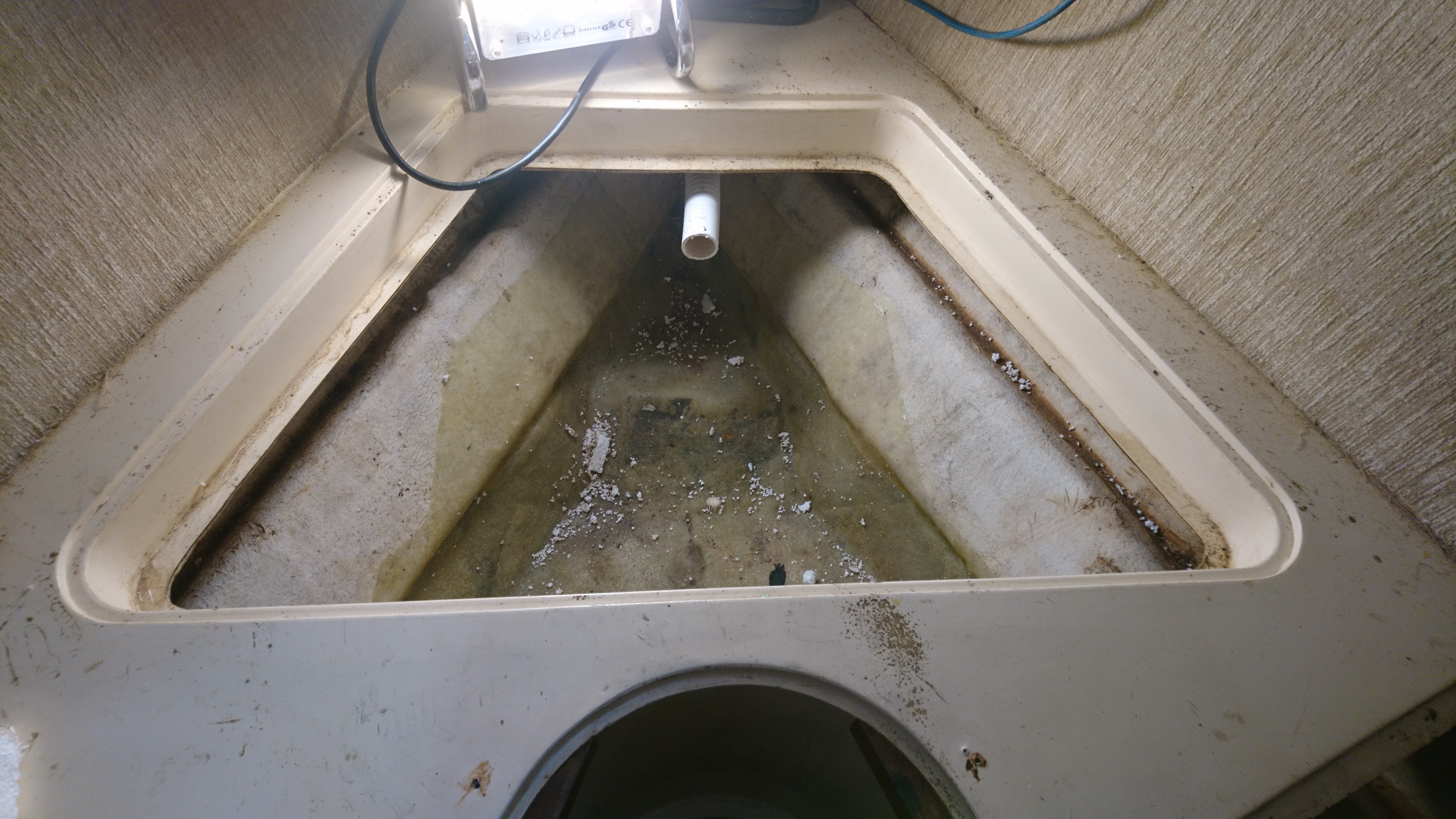
Looking at the hull from the inside can give you a good idea of a suitable location but its often tricky to identify that location from the outside.
So you need to find a datum point that can be viewed from both inside and out that is as close as possible to the proposed location.
Lucky for us this Nicholson 39 has a through hull depth/speed transducer on the center line around 2 feet aft of the proposed thruster location.
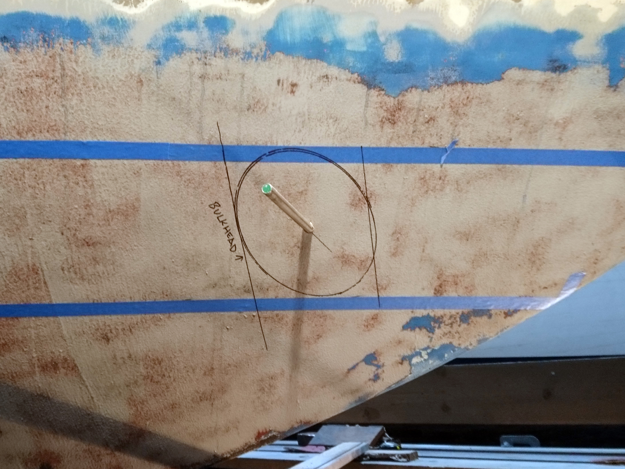
So from this point it was relatively easy to project lines marking the bulkhead position (adding a bit for luck) on the outside of the hull.
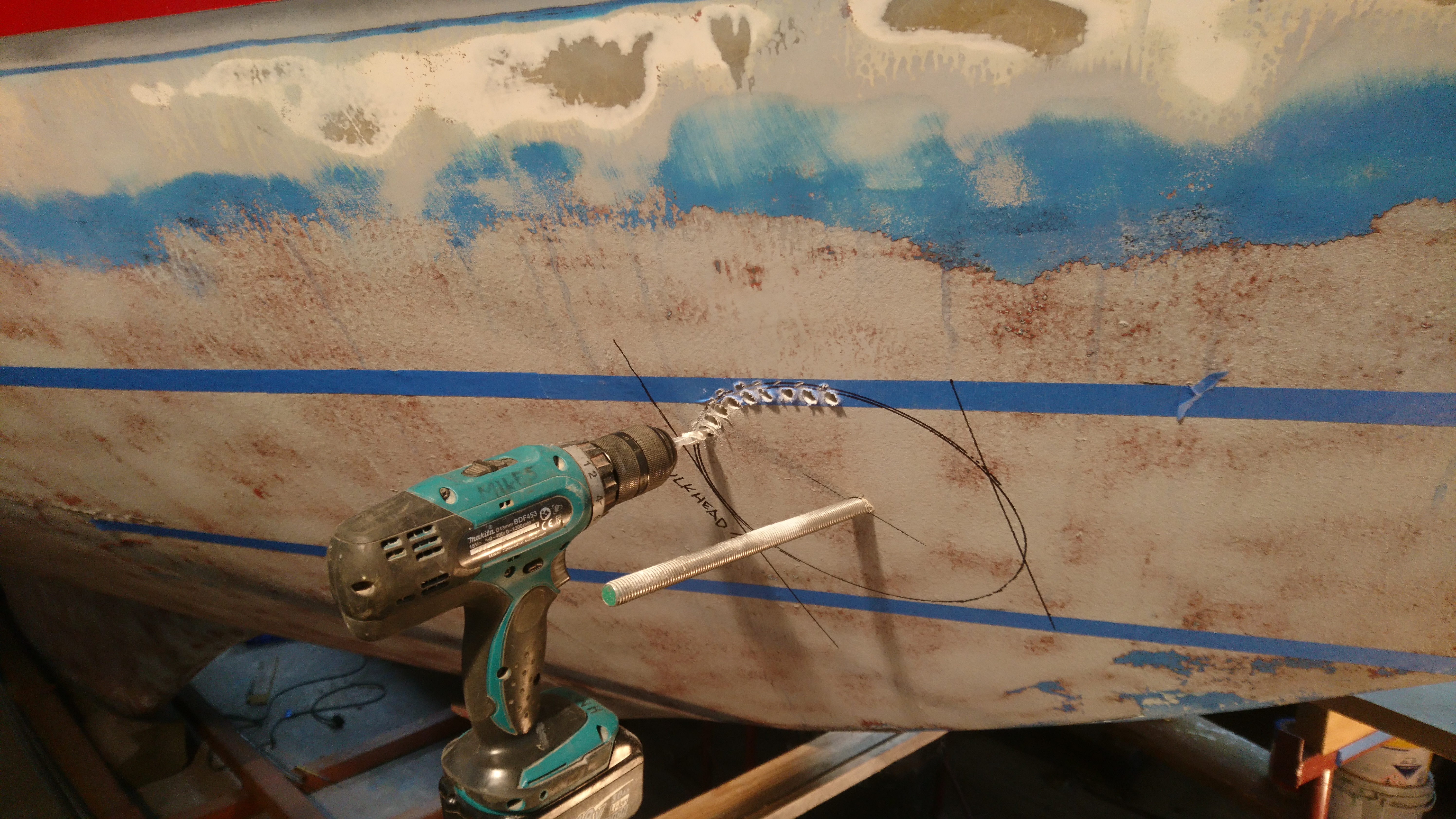
Once the center point of the tube is found a small hole is drilled through both sides and a 5mm dia rod is inserted through to check alignment both inside and out.
When happy its time to open up this small hole out to 12mm which allows us to use a length of m12 threaded bar as the center line rod that won’t bend during the marking process.
We have a special tool for marking the hole but as with most things in a busy yard its gone walkies so I made a very quick and easy tool which actually worked just as well as the “Special one”.
I still prefer to stitch drill rather than use a 200mm hole cutter.
Yes it takes longer but it is far more controllable.
Leaving the center line bar in place gives you a guide so you drill at the correct angle.
I use a 8mm drill for the stitch holes and usually have to sharpen the drill bit a few times on a bench grinder by the end.
Once the holes have been drilled I use a jigsaw to cut from hole to hole.
Unlocking and loosening the base screw on the jigsaw allows you to keep the blade at the correct angle.
Don’t be tempted to try and cut the entire hole with a jigsaw unless you are 100% confident that you won’t wander off line.
I don’t have such a level of confidence so I stick to stitch drilling.
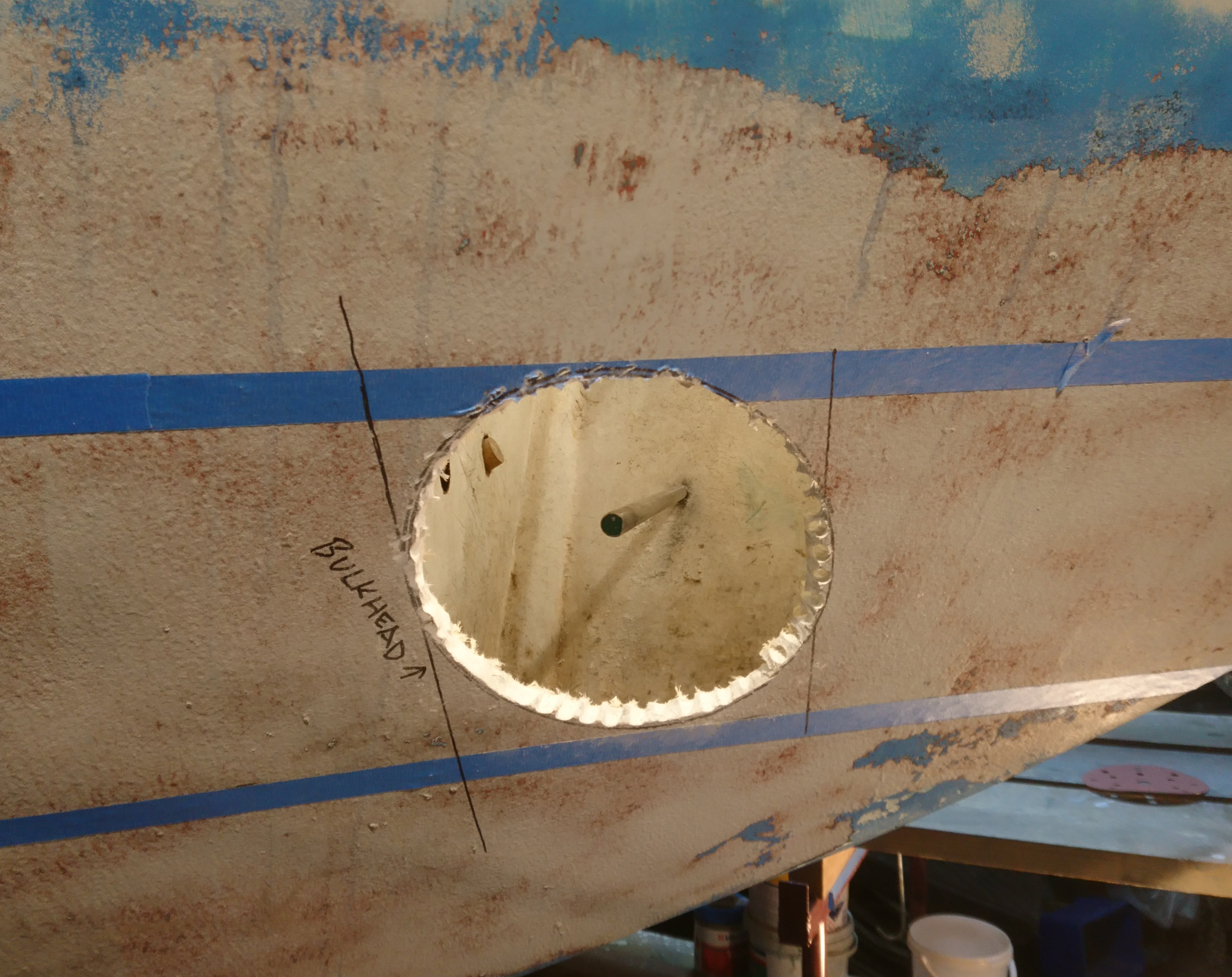
With the centers removed its an easy if dusty job of removing the rough drill slots using a sanding drum with 40 or 60grit paper.
A few words on the dust.
It’s particularly pernicious, intrusive. smelly and definitely anti social stuff.
You need a FFP3 mask and a disposable hooded overall over your overall.
Inside you need remove everything from the forward cabin and seal the doors.
Even then you will find evidence you missed a bit.
Outside the hull its much harder to control so its damage limitation, we evacuate that shed and the guys move to one of the others, grumbling under their breath until I’ve finished and fired up the vacuum.
Holes in boats are never a good thing.
Huge great holes in a pounding area of the hull are even less good idea.
So I employ a belt and braces approach and ensure I bond the tube externally as well as internally.
To do this I chamfer the outside of the holes so I can get a good 15mm glass thickness around the external joint.
Initially I cut back 50 or 60mm back from the main hole but this will be increased when I get to glassing.
Whilst the nominal dia of the tube is 200mm, because its cut at an angle the largest distance from one edge to the other is 270mm.
So the proposed scallops will need to start at 270mm wide and extend at least 700mm aft.
Looking from the front I can see I’ll need a scallop depth of 45mm.
The next task is to make a mold for the two scallops.
The initial layup of the scallops needn’t be too thick as additional layers will be added later when bonding it to the hull for both inside and out.
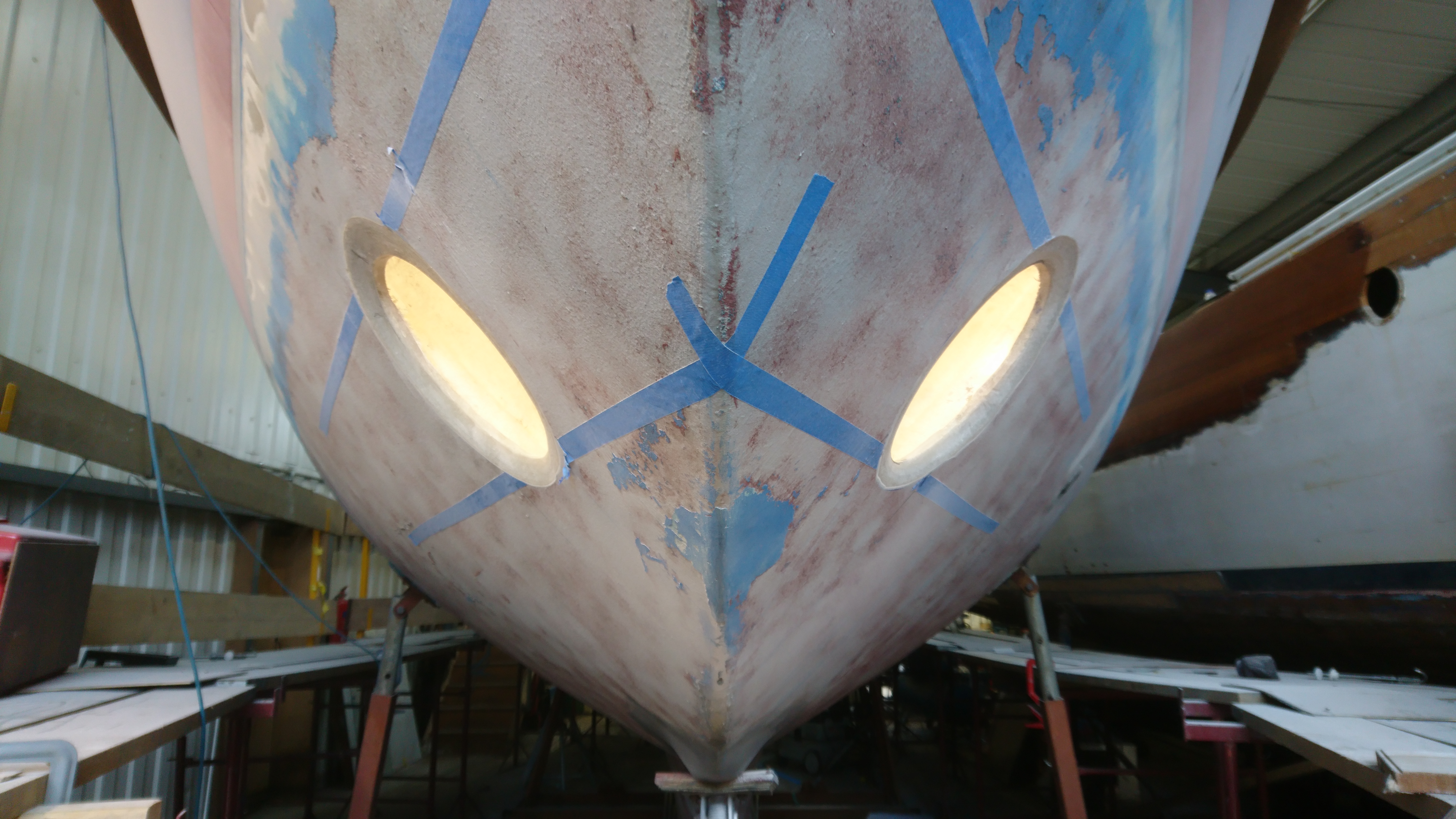
The first scallop hole cut into the hull is always a little scary as the hole is BIG and you need to be sure you have it in the right place which on a boat with constant curves is not easy though your eye is pretty good at alignment and often better than a tape measure as many hulls are not as symmetrical as you might think.
Grinding this scallop hole produces prodigious amounts of dust, so sheeting off the area is important and covering every inch of your body in protective gear, vital.
Eventually its a case of grind a bit, test dry fit, grind a bit more, until it all sits nicely together.
Whilst in the early stages we assessed whether there would be sufficient access to glass the tube and the scallop to the inside of the hull, now we have a dry fit you need to look more closely at exactly how you propose to glass it all in.
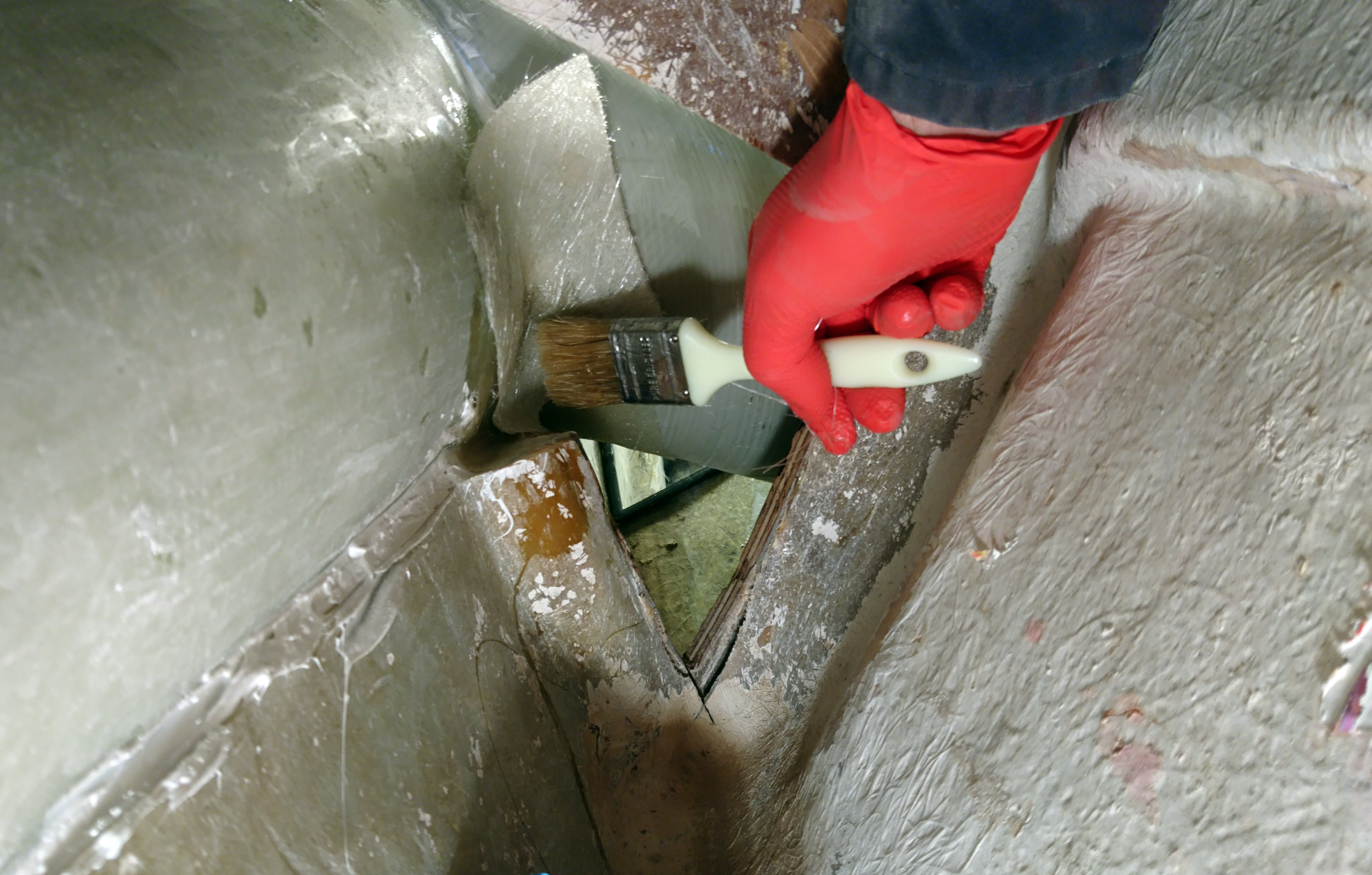
Obviously the underside of the tube and scallop will be the hardest to get too so I grabbed a brush and roller and ran a test to check I could get to all the joints.
As a result a little more bulkhead had to be cut out of the way and will be replaced later.
When happy with the hole on one side its an easy process to make a cardboard template to mark out the other side.
Then its a case of rinse and repeat.
Moving inside the worst job is grinding back the interior glass to provide a good key.
I aim for a border of clean glass layup at least 6 to 8 inches, followed by scrupulous cleaning of the dust with a high power vac, then a good blast with an airline, finishing off with a thorough wipe down with acetone.
The bonding area of the tube and the scallops get the same treatment before final positioning.
We are using polyester resin and layup as opposed to epoxy.
It’s very much cheaper and faster to layup and the thickness of layup will be immensely strong, the additional weight not being a factor on this boat.
The tube and Scallops are bonded into place using bonding paste, which is the same stuff most decks are bonded to the hull with these days.
The layup is time consuming, especially the tricky glassing under the tube.
I use a couple of mirrors and a long handled brush and roller.
It takes a bit of practice working upside down using a mirror but its obviously imperative that you get a good, consolidated layup.
When glassing the tube it’s worth spending time cutting the glass for each side before hand and laying them on top of each other in order of use.
This is an easy way of ensuring you get an even number of layers on each side as its very easy to lose track of how many you have done.
Due to the shapes and angles involved you have to use short pieces of cloth around a foot long and a maximum of 150 wide.
The first layers are chopped strand as they provide a better grip to the old glass than woven cloth.
Then I move onto 100mm wide biaxial tape and then 450g 150mm wide biaxial tape.
A top tip here is to wet out the glass on a scrap strip of hardboard first and then carefully transfer it to the tube/hull joint which ensures you don’t get any dry areas, at the same time its a lot easier to wet out using the minimum amount of resin which is just as important as too little.
A very common fault of the amateur laminator is using too much resin which will result in a brittle and less strong laminate.
It takes me at least three full days to get all the laminating done, its not something that cannot be rushed.
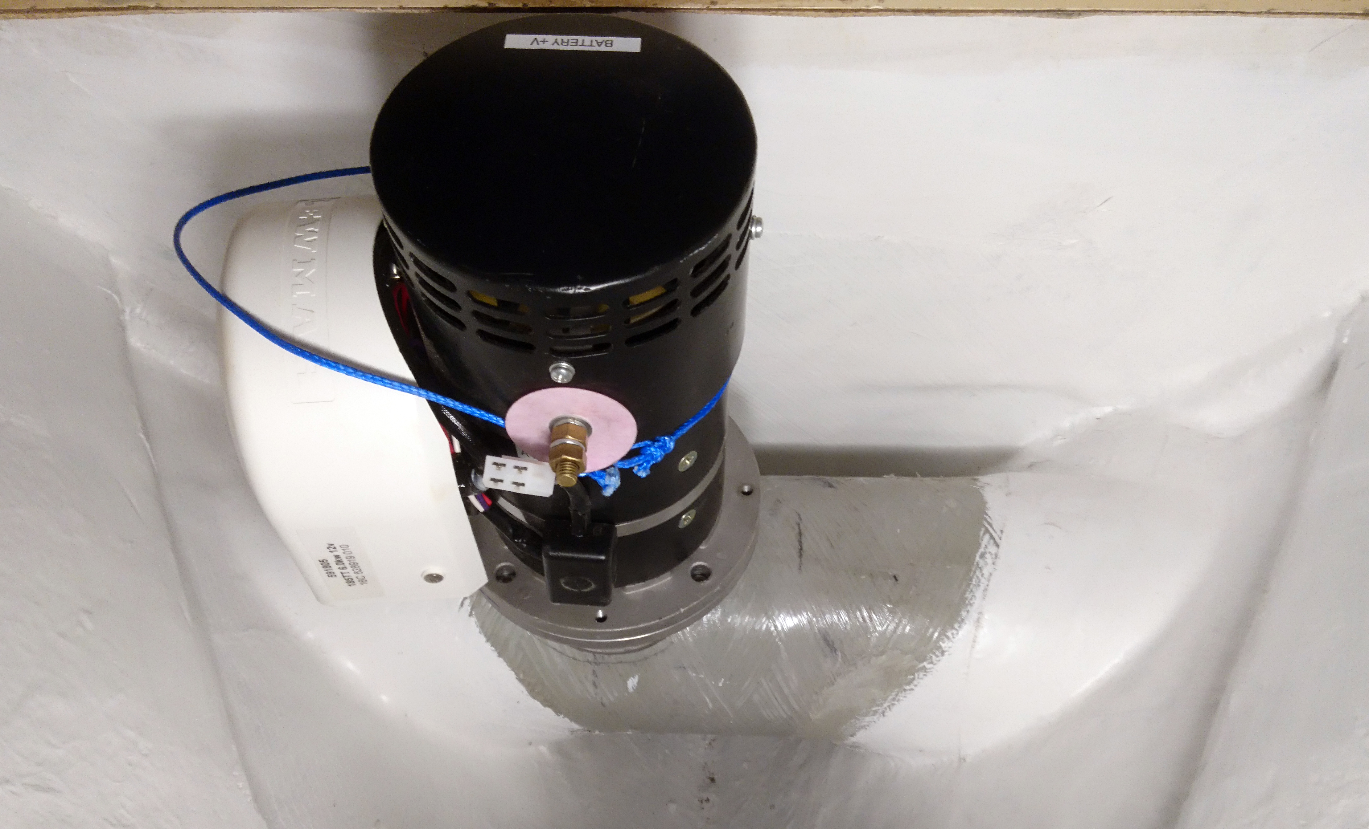
One of the trickiest jobs is locating the position of the gearbox in the tube.
You only need to be a gnats out and the prop will foul on the tube.
So adding a few strips of masking tape you can mark up the position accurately taking into account that for the prop to be in the center of the tube the motor has to be offset to one side or the other.
Lewmar (bless them) provide a template page in the installation manual to aid fitting. They even call the page “Cutting Templates”.
They then ruin all this work by watermarking the page “Not to scale”! and sure enough they are not to scale but the really frustrating thing is not by very much at all.
Completely bonkers.
So ignoring the manual I use the actual saddle as a template and mark and cutout the require holes.
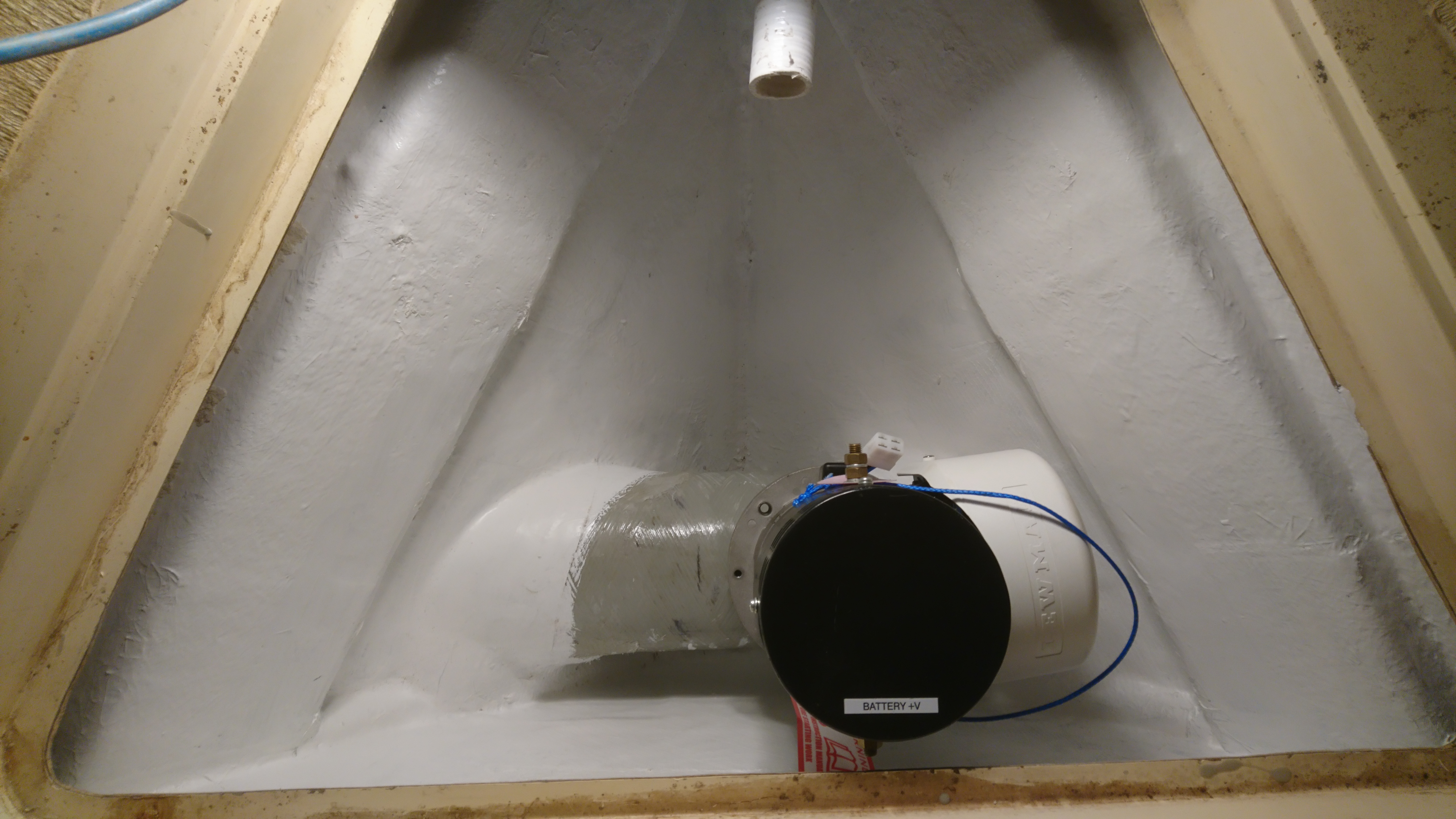
The owner had decided to locate the thruster battery next to the tube so once the tube and scallops had been glassed, and the gearbox and saddle position settled, the next job is to glass in some shelf supports and then make a template for the shelf.
For this job, strips of gash plywood cut into strips and a glue gun are your friends, a fast and accurate way to template any panel on a boat.
The shelf is made from 19mm marine play and is glass sheathed.
To finish I applied a few coats of gel coat and topped it off with gel coat with added wax in styrene, otherwise know as flowcoat or topcoat gel coat.
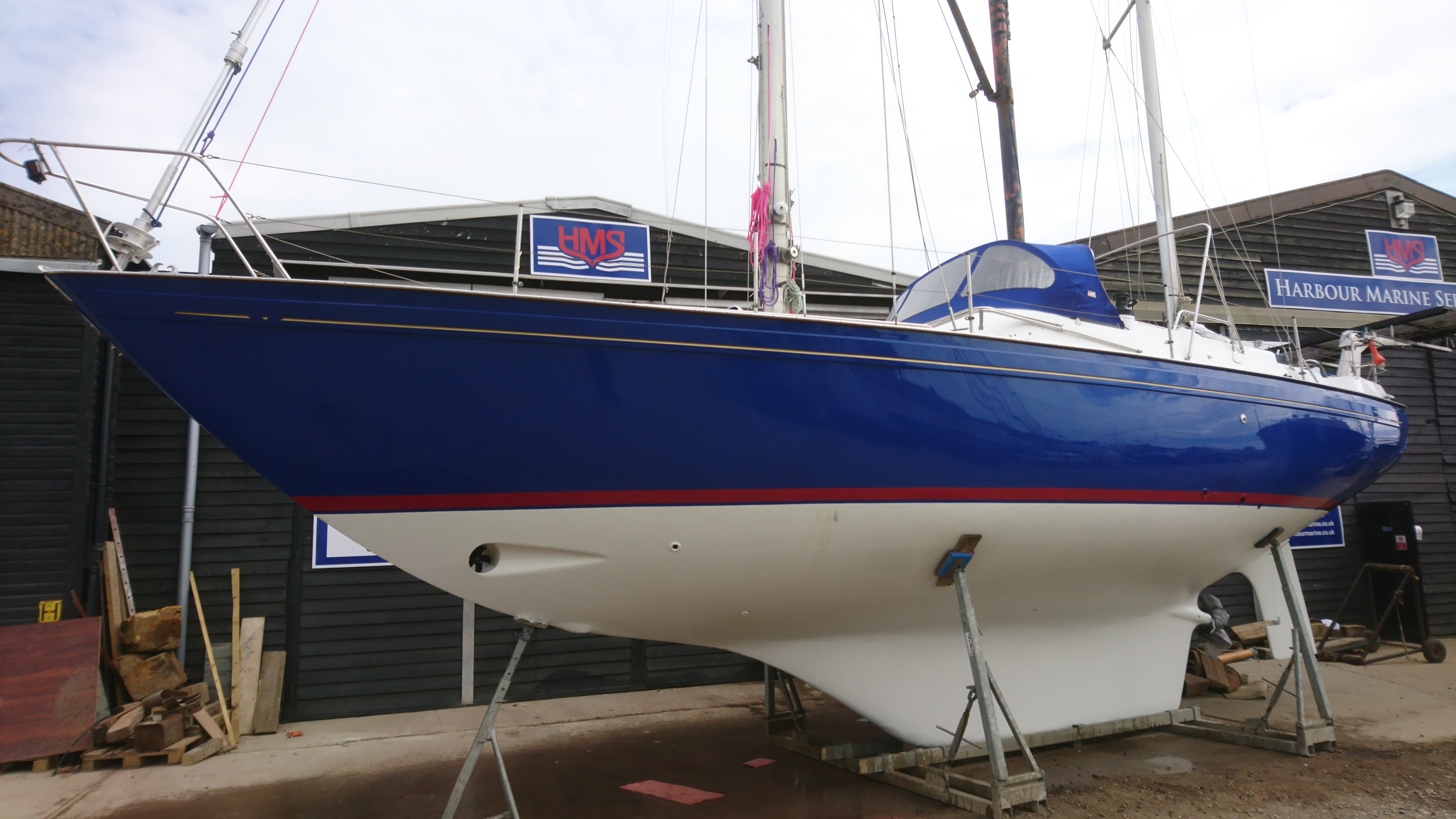
Moving back outside the tube and scallops are glassed to the hull and are then made fair.
Scribbling in marker pen is a great way to see highs and lows when sanding and filling.
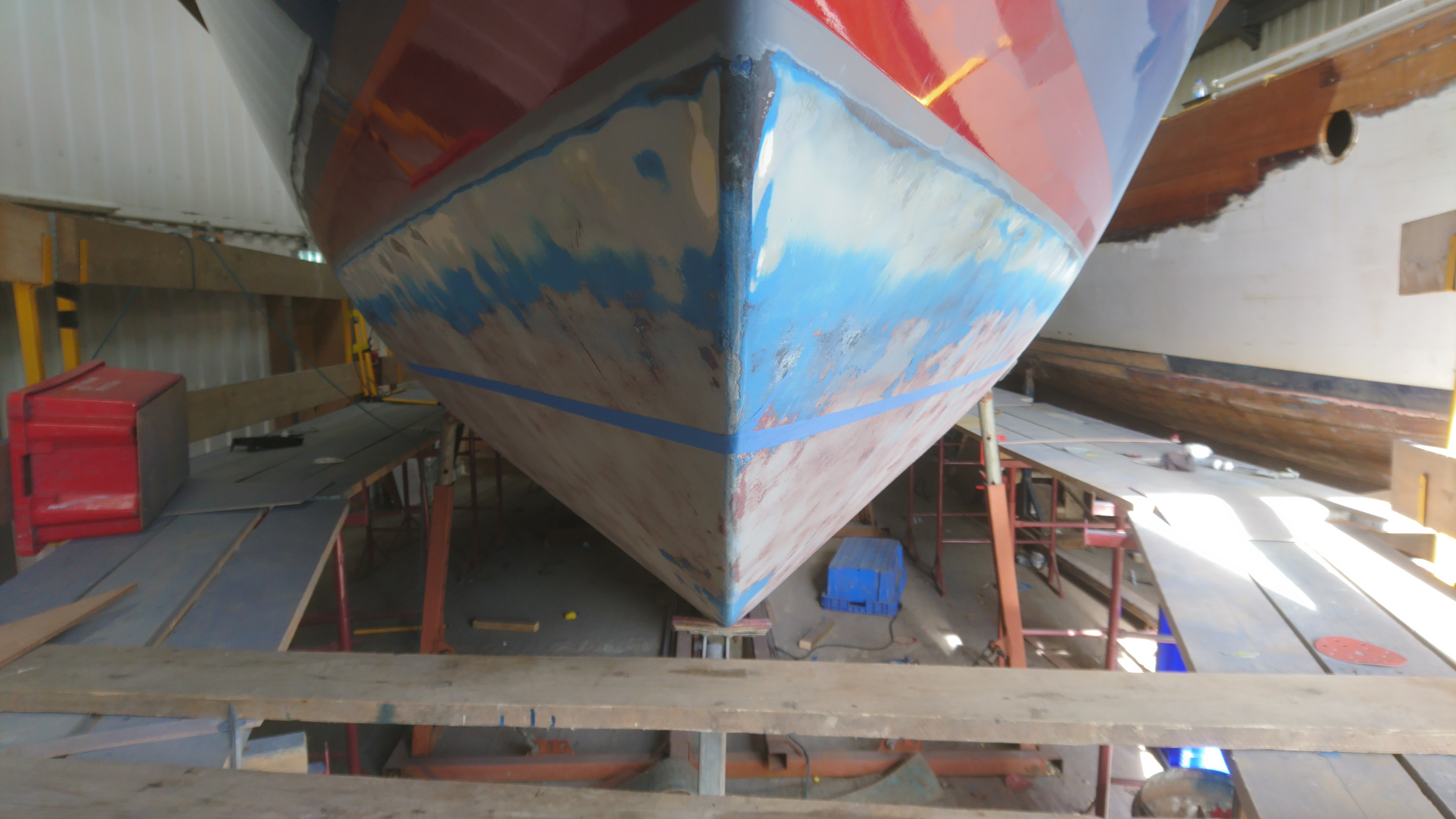
Whilst the boat was in the shed we had also resprayed the hull and grit blasted the underwater sections and applied four coats of epoxy, then primer then anti-foul.
A point of note here is that epoxy is not as good at bonding to new polyester as it is with old cured grp. The styrene in the layup takes time to leach out during the curing process, (it can take months to fully cure) and this can sometimes effect the bonding ability of the epoxy coating in direct contact. You can speed up the process by cooking the laminate but this is obviously not an option.
So we made sure that the new glass is well keyed and primed and we’ll check on the condition at the end of the season.
The test running will have to wait as the owner wants to carry out the wiring himself which will save him a few pennies, hopefully.
If not, I’ll be running another article shortly on rewiring a partially wired bow thruster.
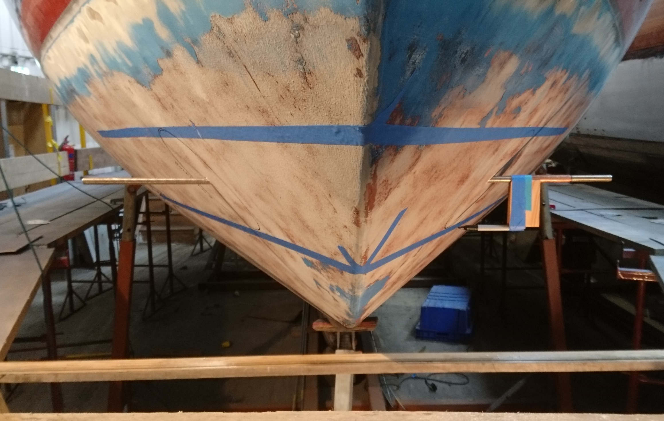
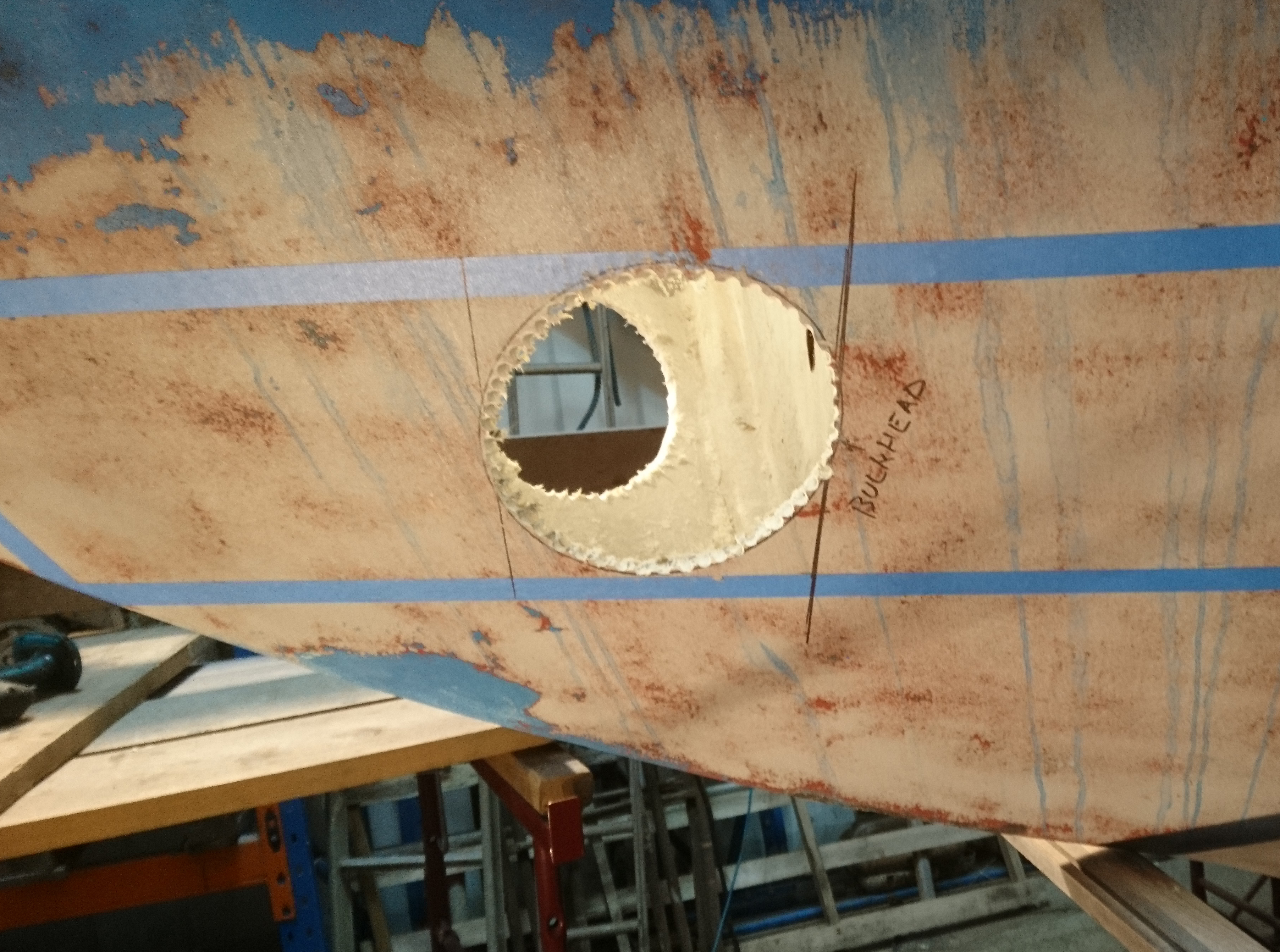
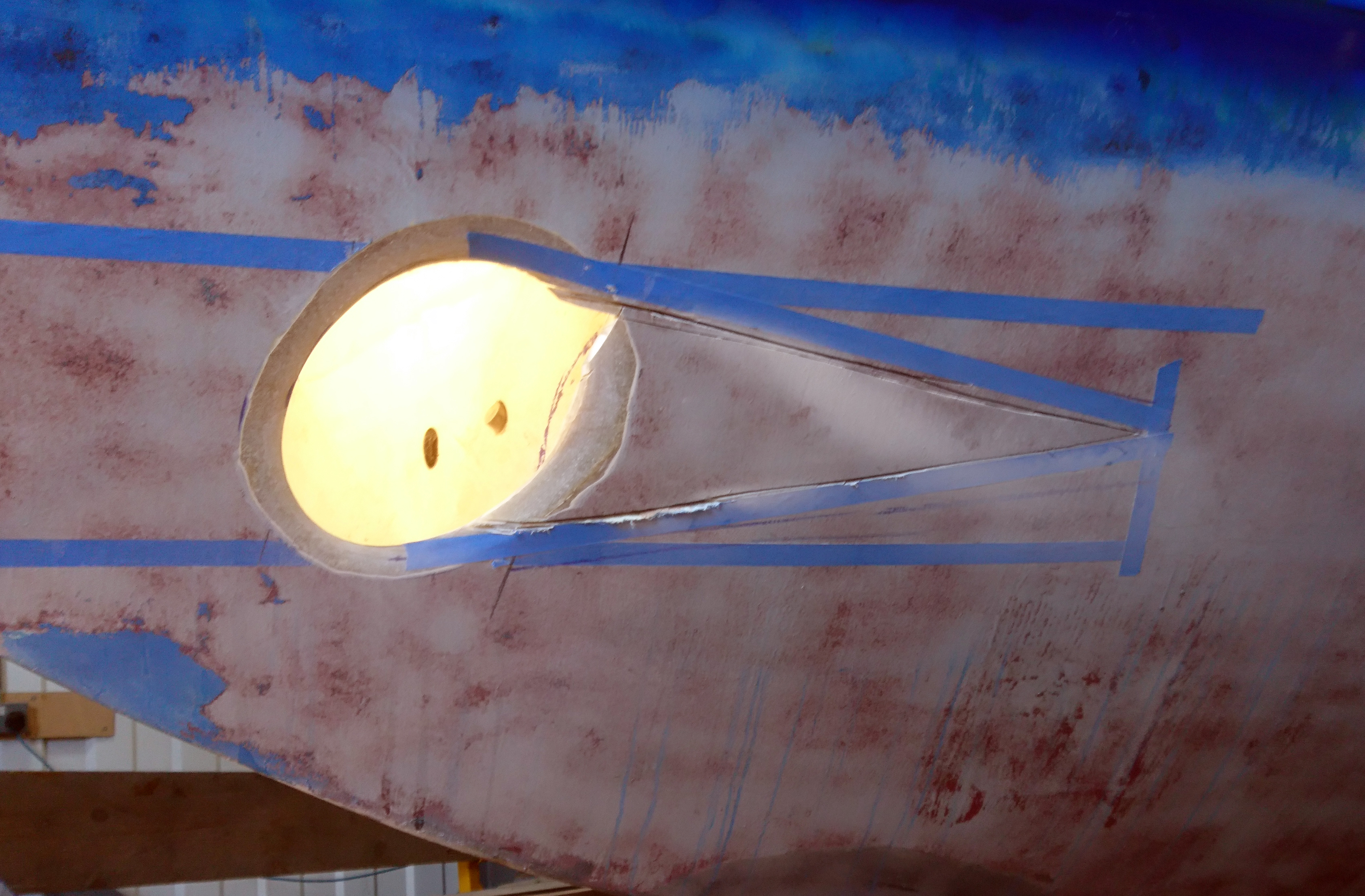
The tape line marks a tube diameter below the waterline.
Top edge of the tape sets the height of the top of the tube.
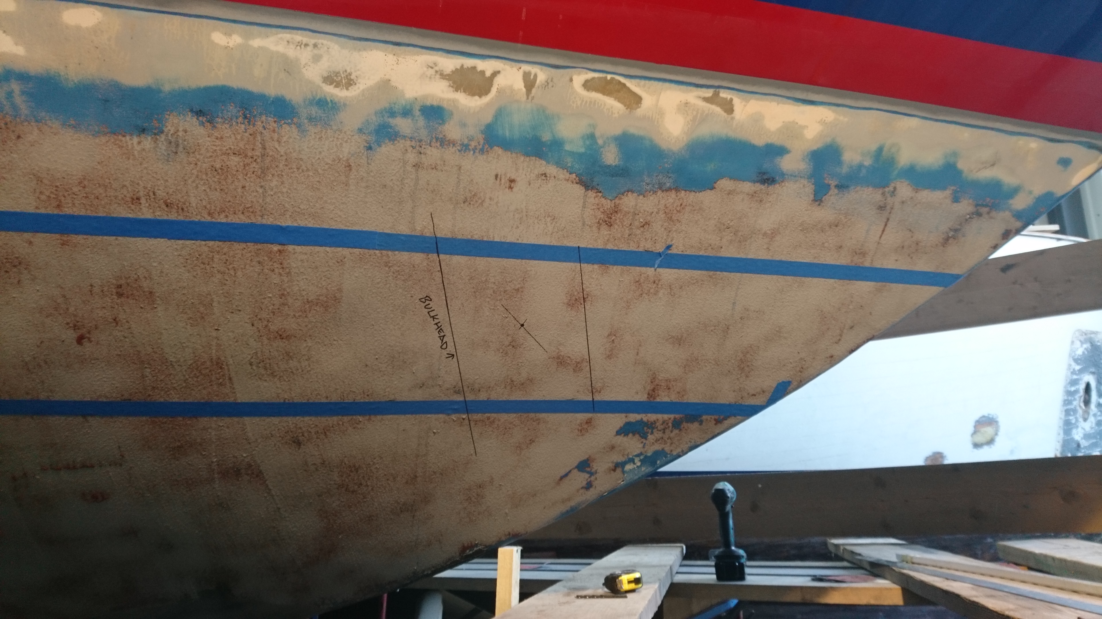
Using the Log skin fitting as a datum point that we can identify both inside and outside the hull we can then check the location of bulkheads and knees.
From this we can choose the best place for the tube.
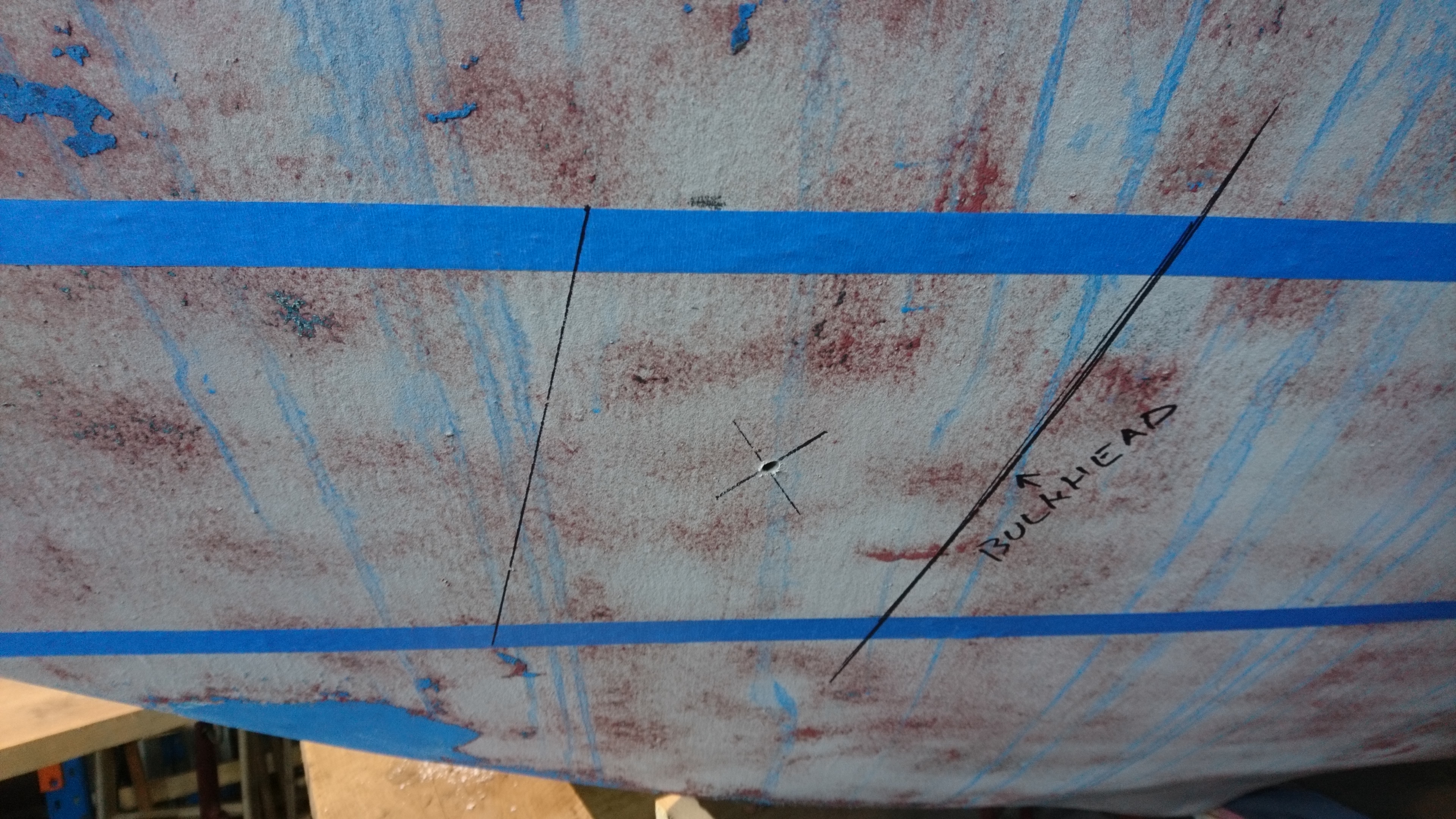
Drill a 6mm hole through both sides and then check inside to see if they are level and are equidistant from the datum point.
Complication on this boat was that there was a sub floor glassed in above the pilot holes.
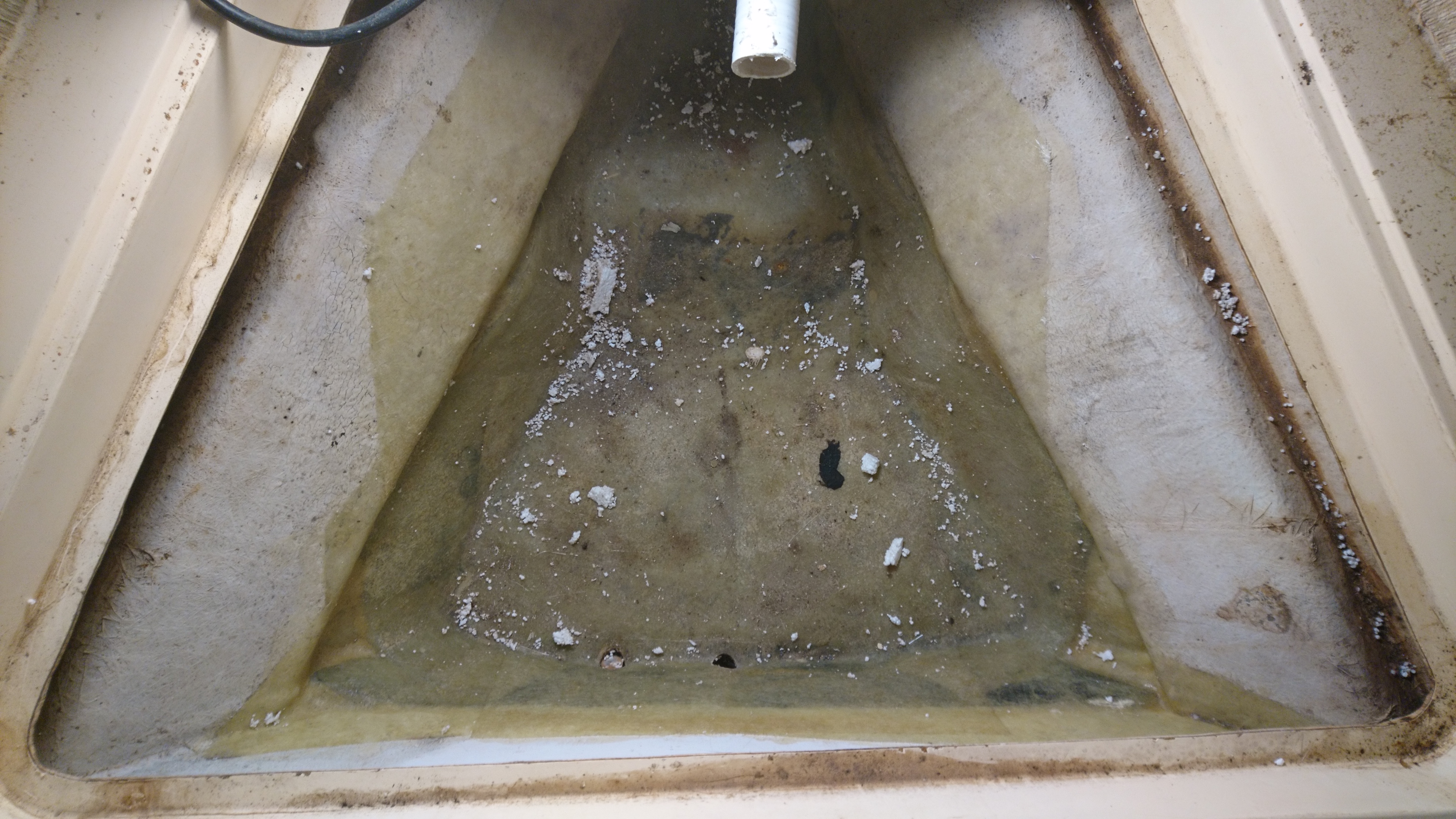
This section will be cut out and removed.
Once happy with the position of the center holes we drill out the holes to 12mm and insert a length of M12 bar through the hull.
This allows us another visual check on alignment and gives us a new datum to draw our cut out sections.
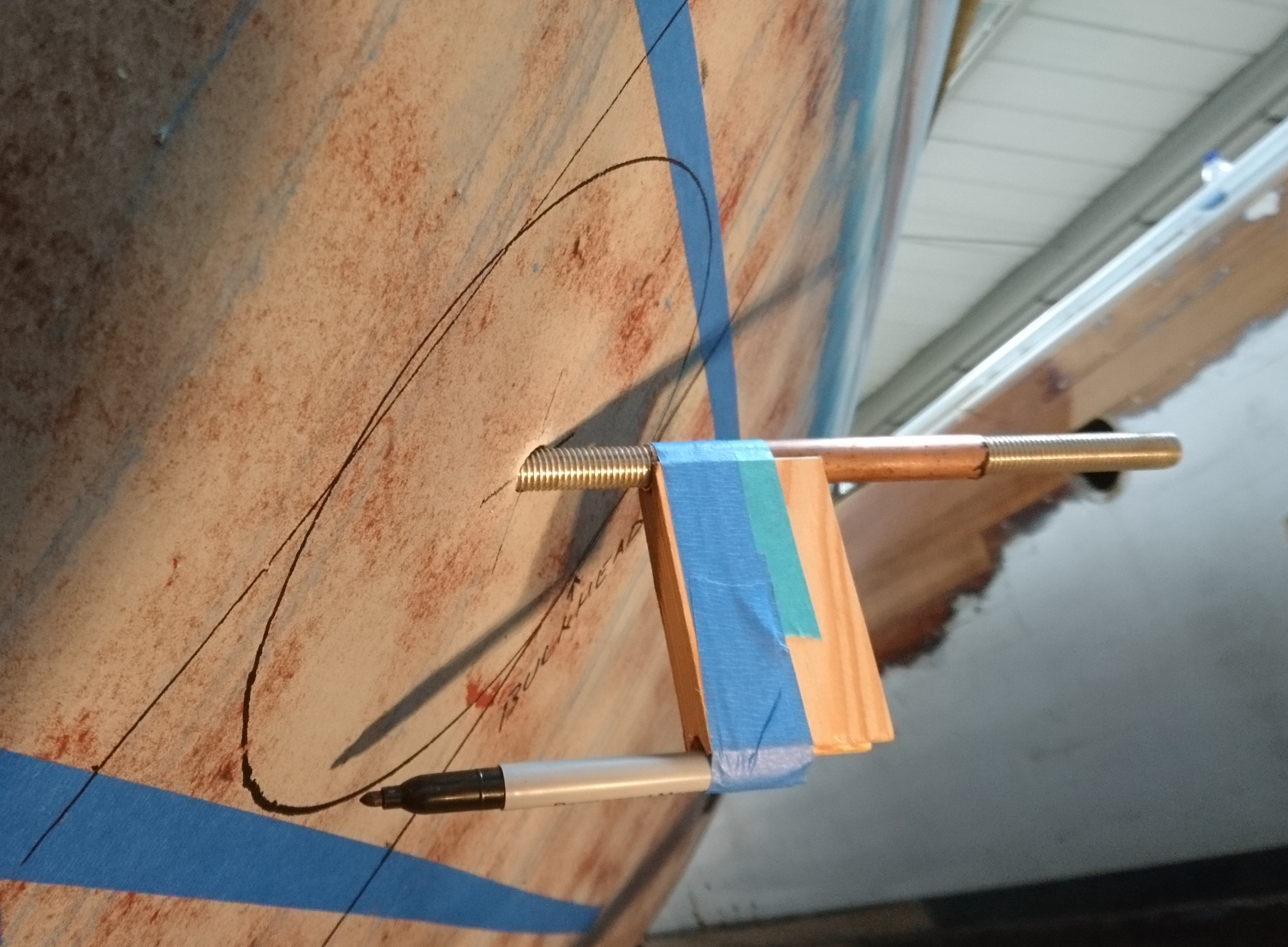
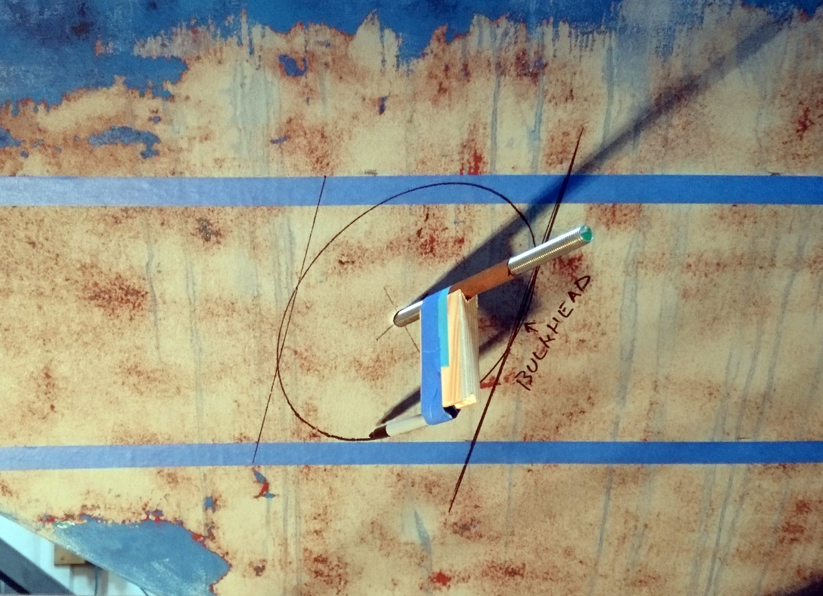
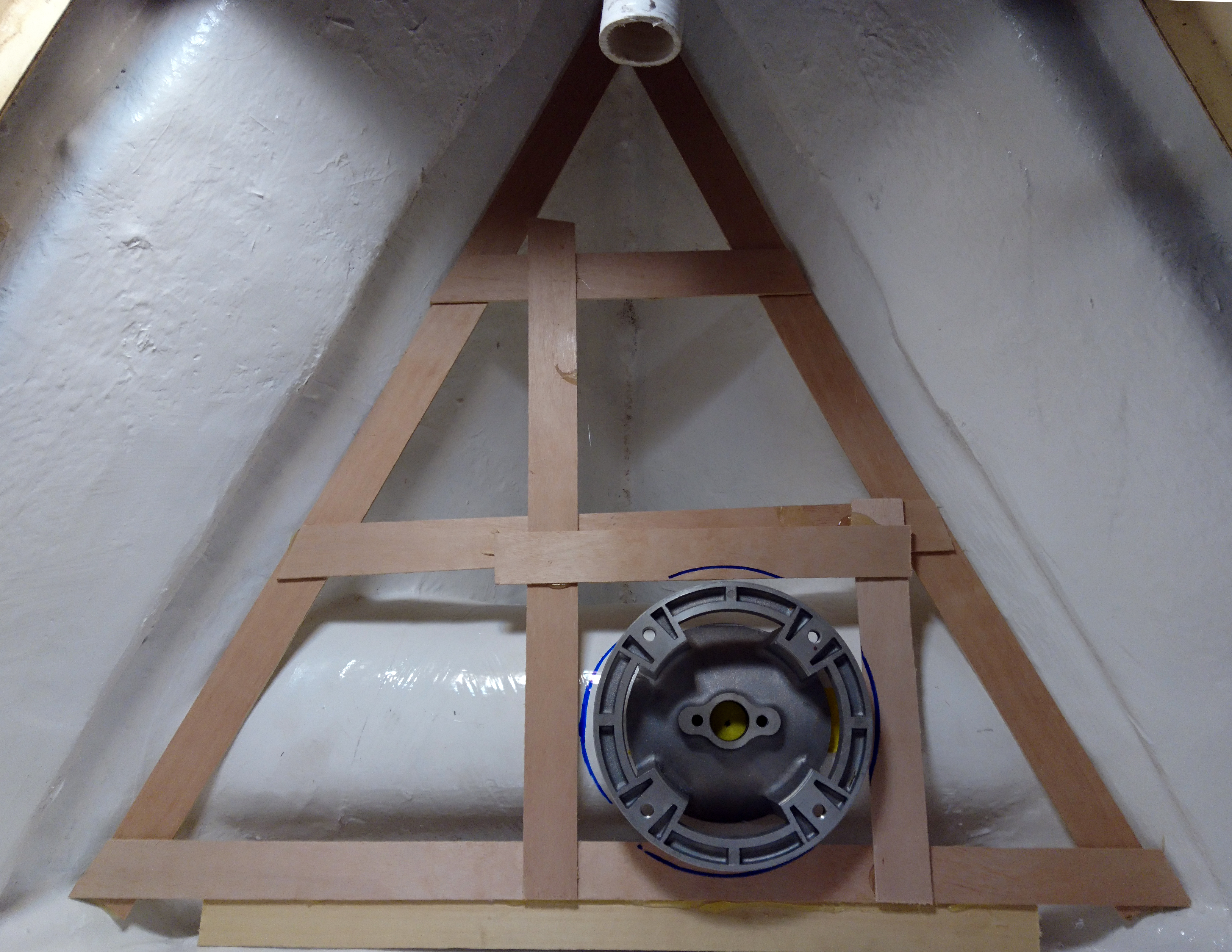
I made a simple tool to mark the tube entry using a piece of copper pipe, scrap wood, a pen and masking tape.
The tube slides in and out on the threaded bar and makes life a whole lot easier to mark what is actually quite a complicated shape.
We could have used a big hole cutter but in my experience its fraught as it tends to snag and tries to snap your wrists off.
So I opt for stitch drilling which I find far more controllable.
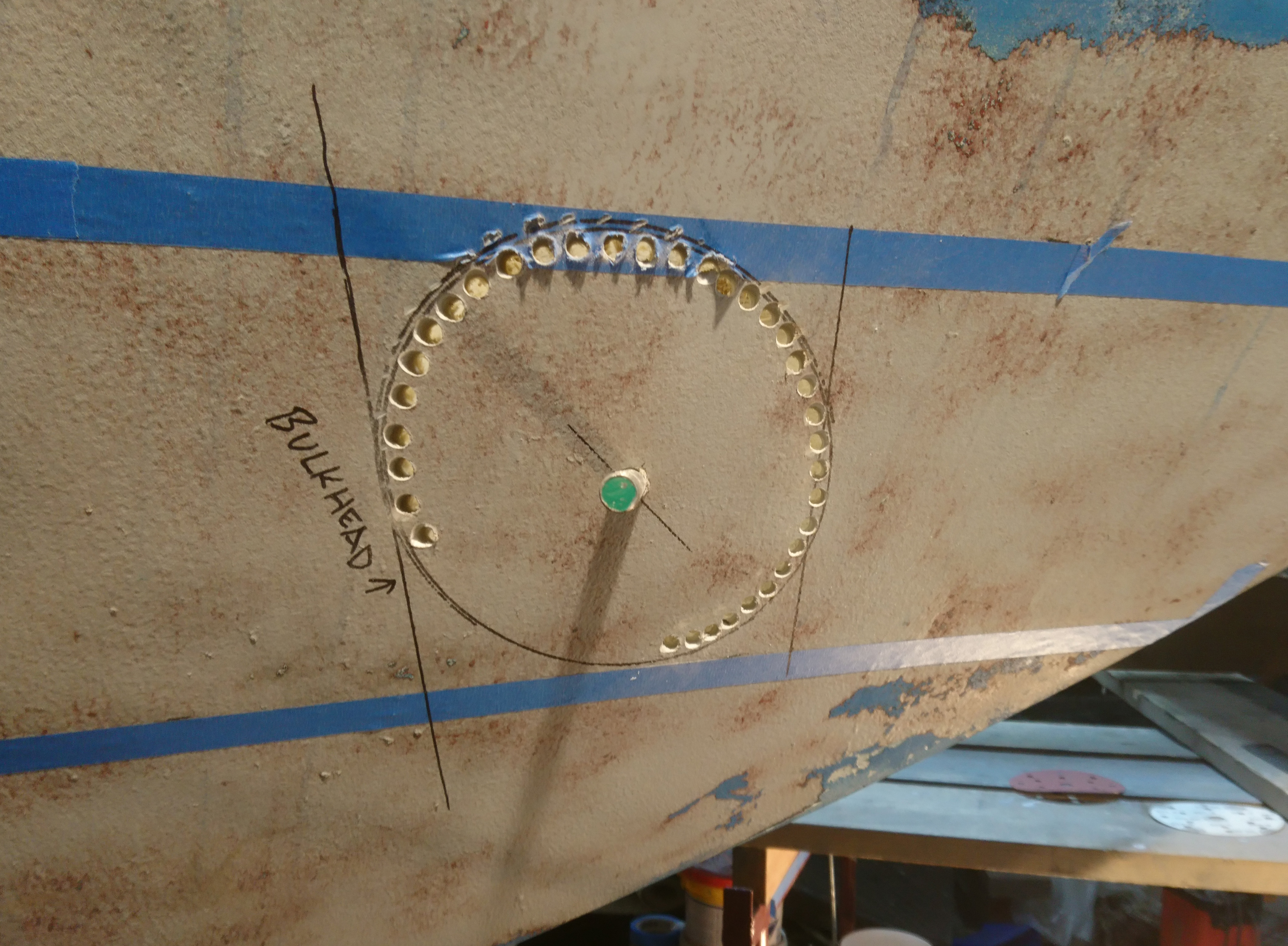
This looks like the center is not er, central.
It is, have faith.
I use a jigsaw to cut between the drilled holes, making sure the base of the jigsaw is unlocked so that as you cut round you can keep the blade at the right angle
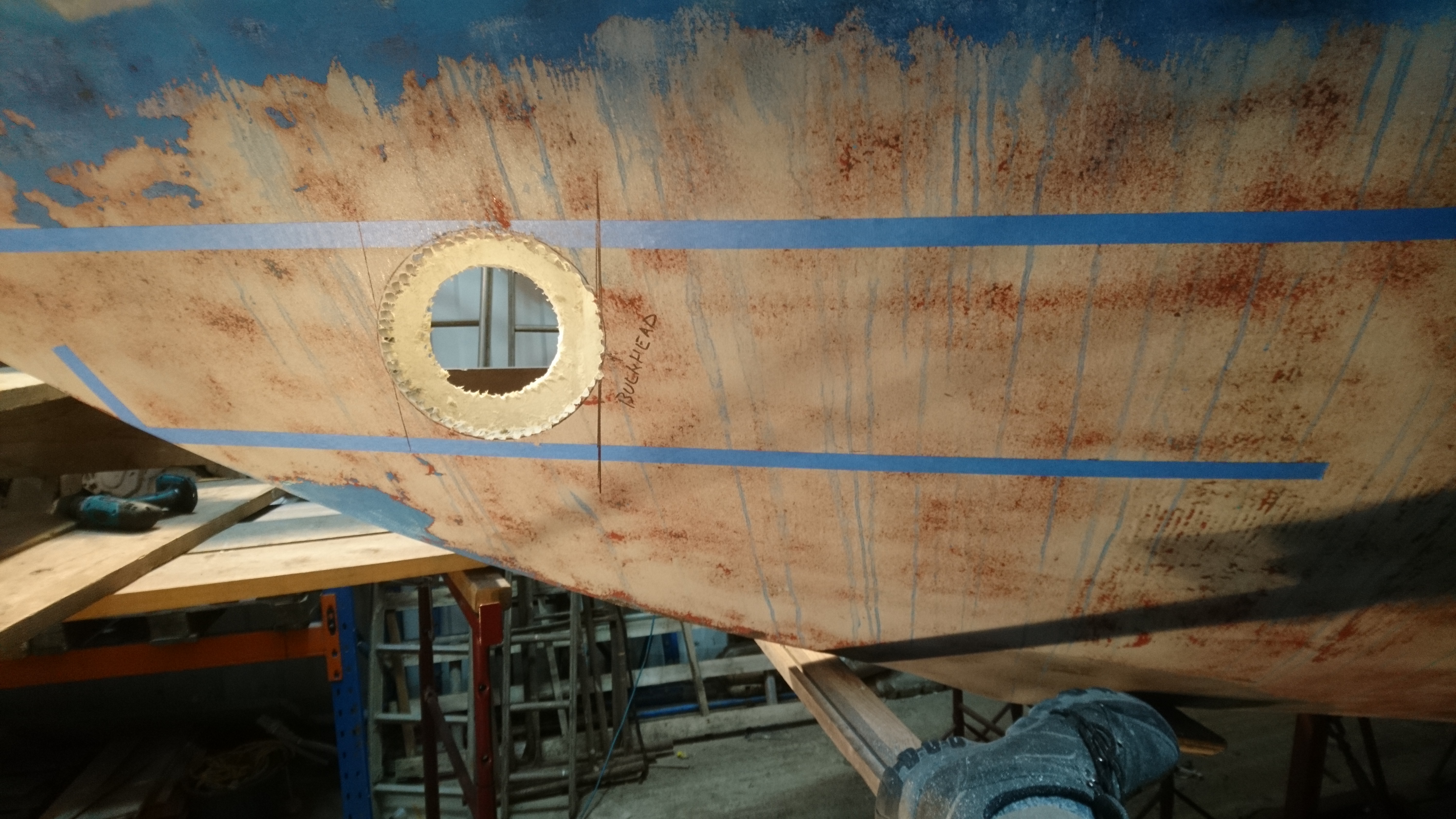
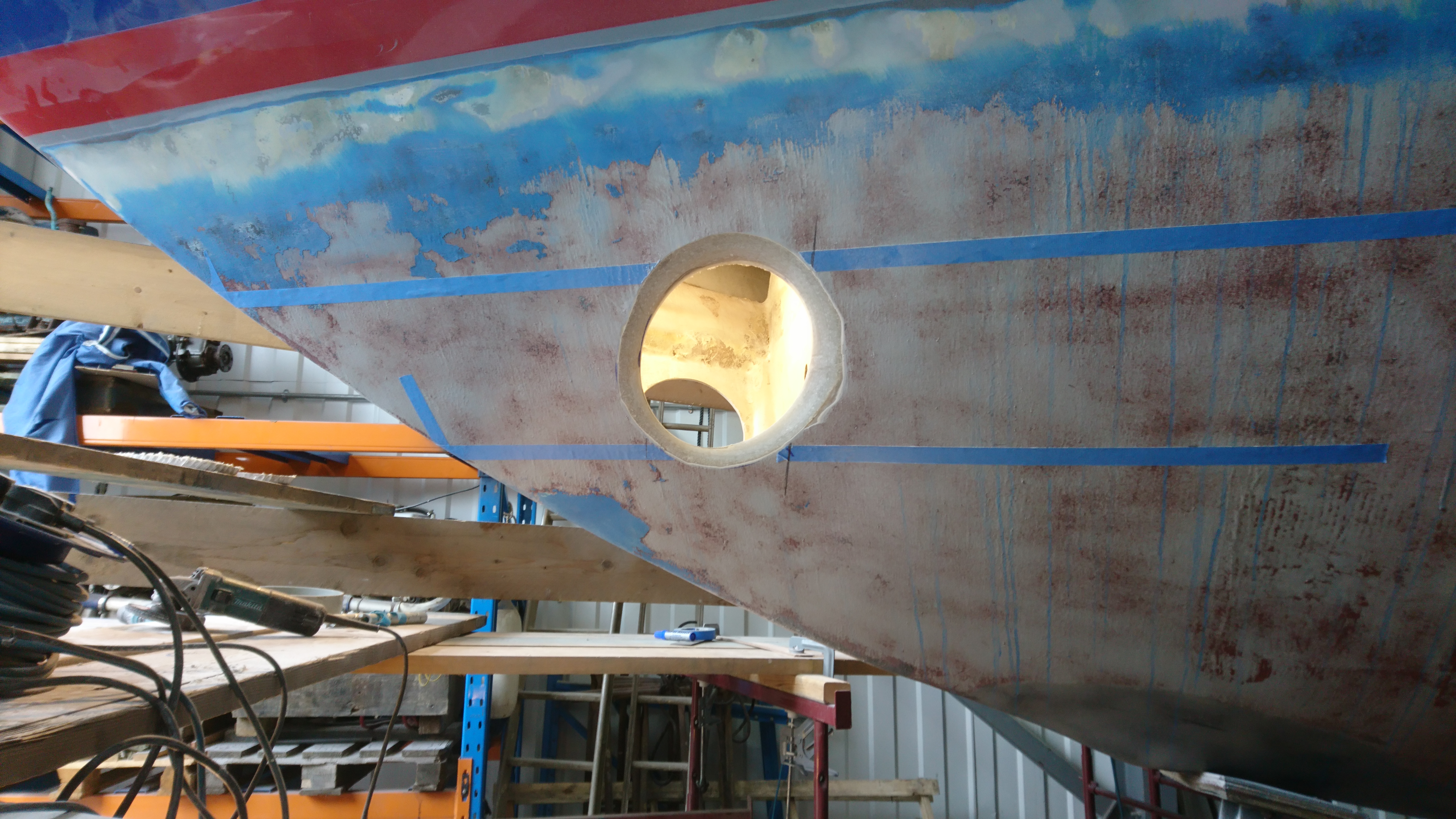
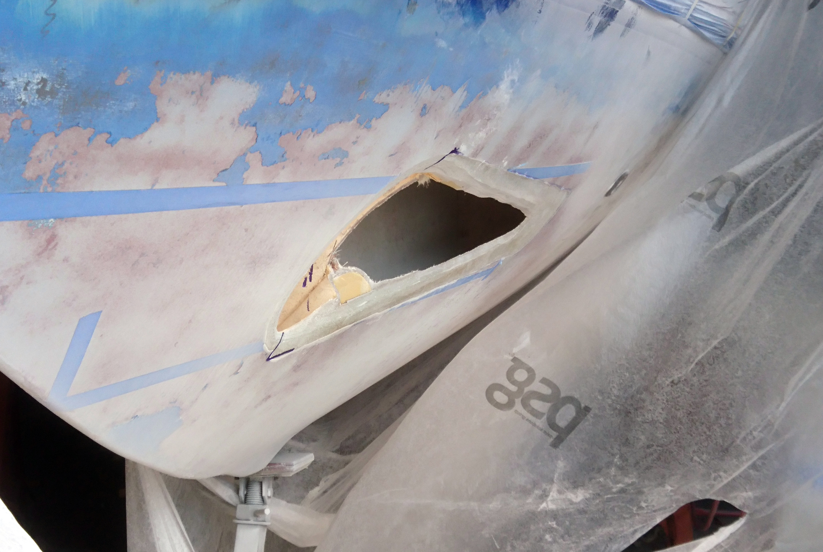
After a couple of hours we have two dirty great holes in a customers boat and square on they even look round.
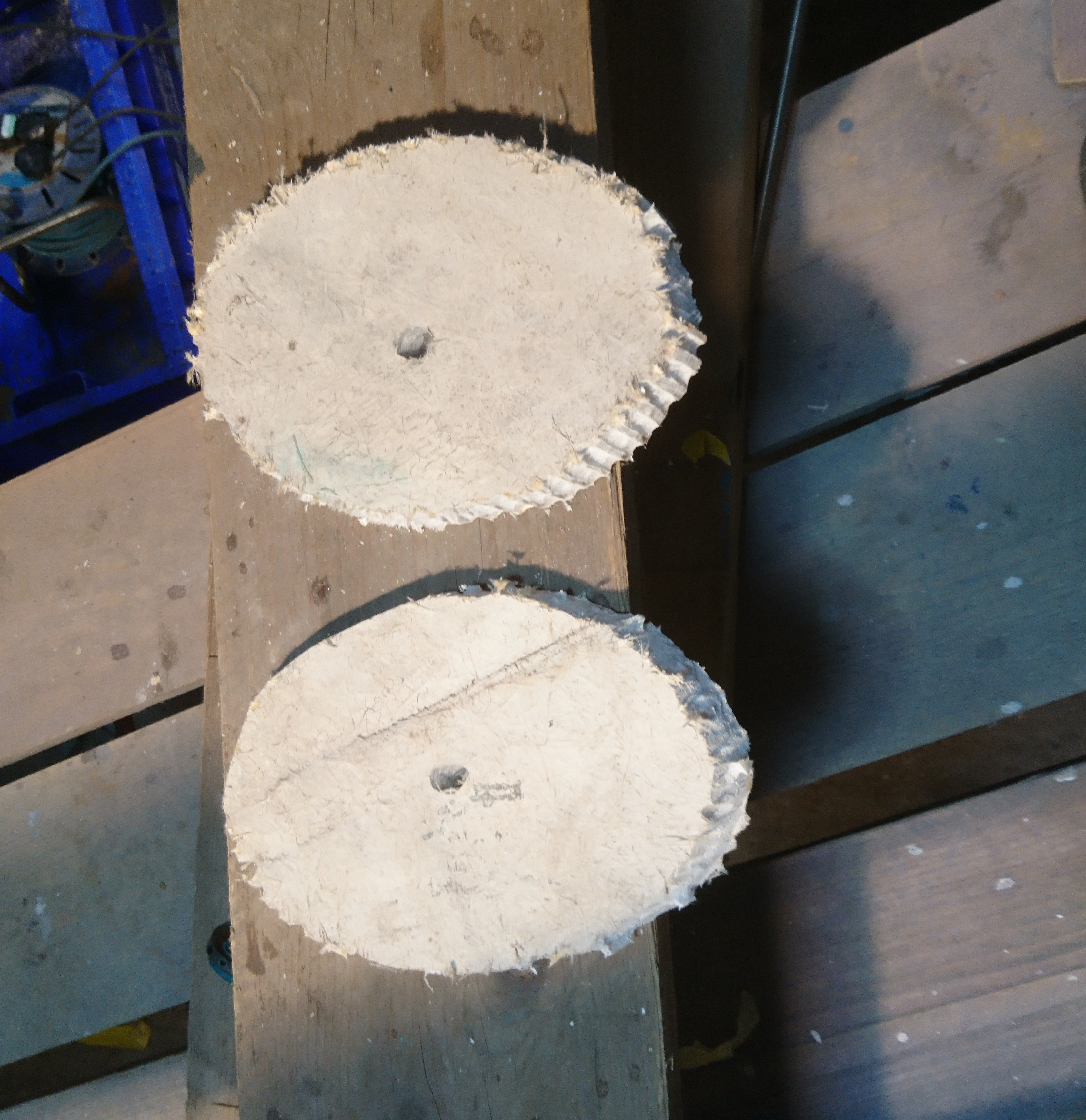
The sections that were cut out show just how strange a hole for a perfectly round tube can be.
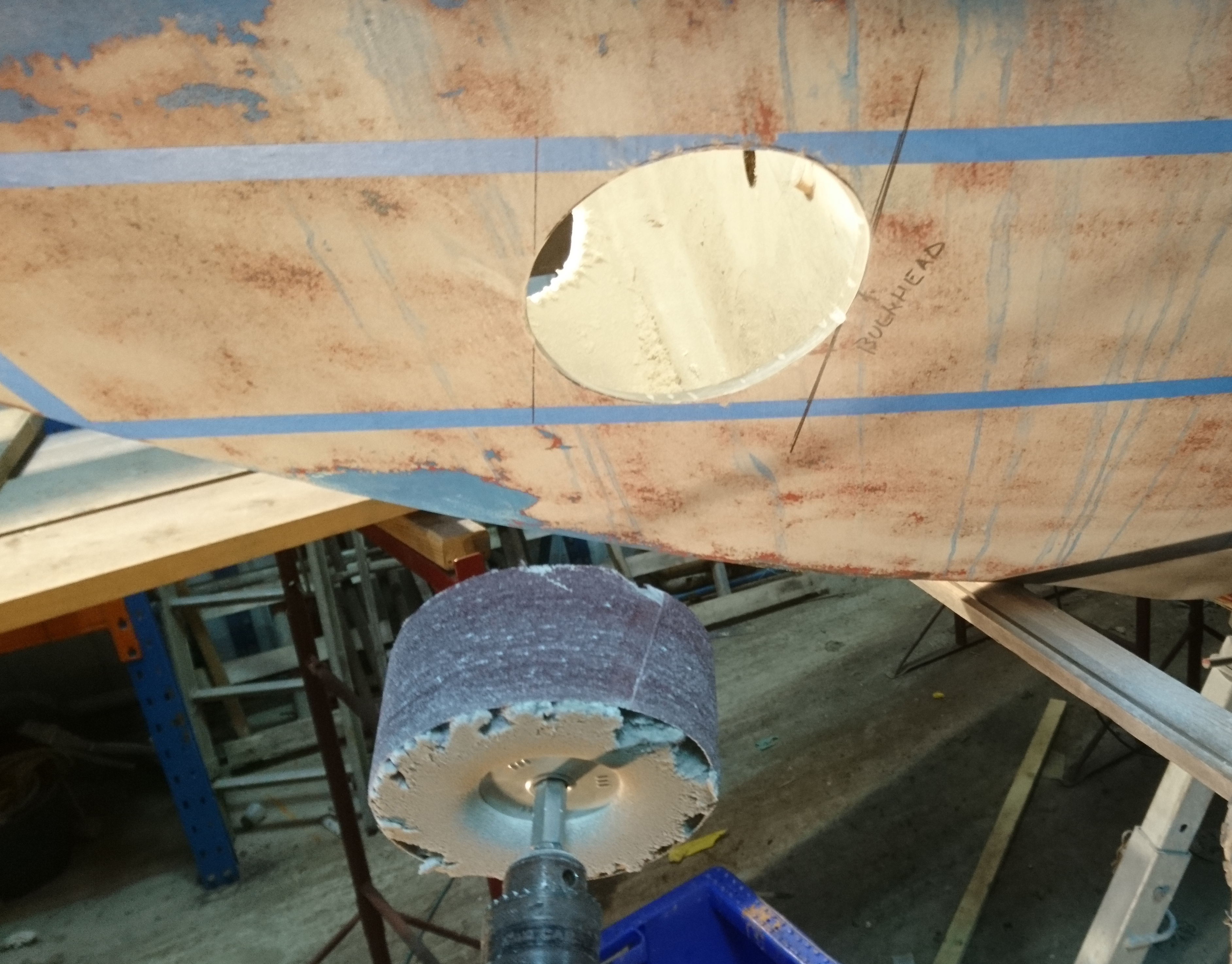
I use a large dia foam sanding drum with 40 grit paper to fair the hole out to the marked line.
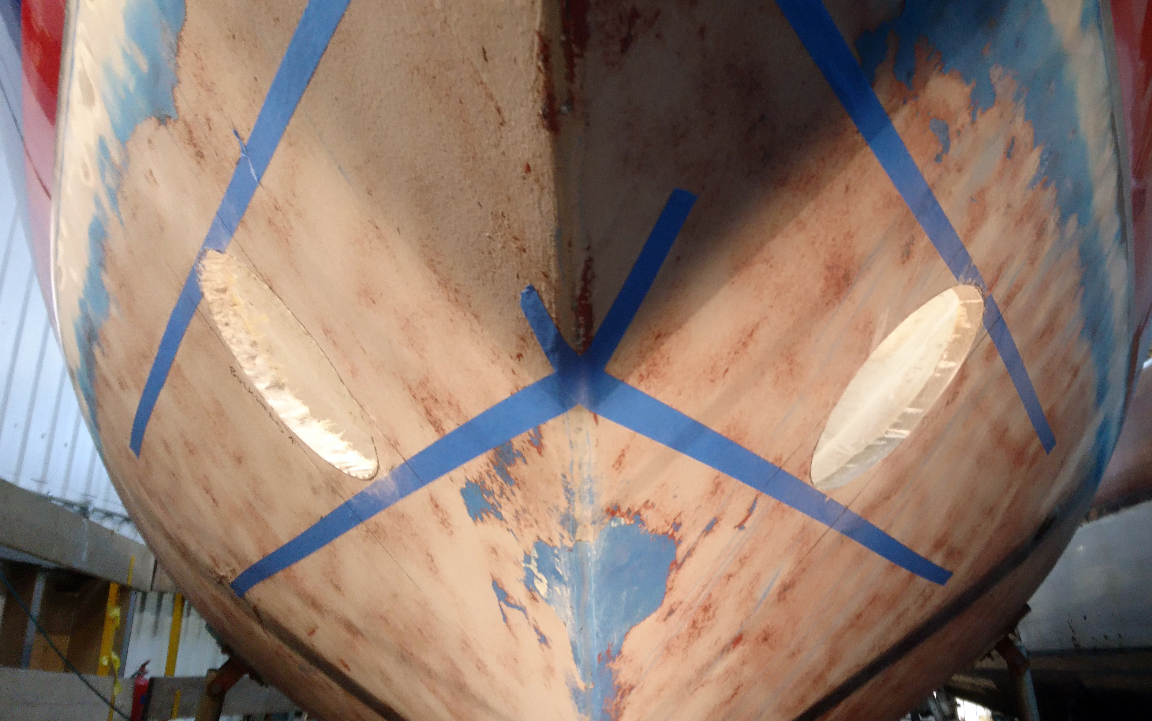
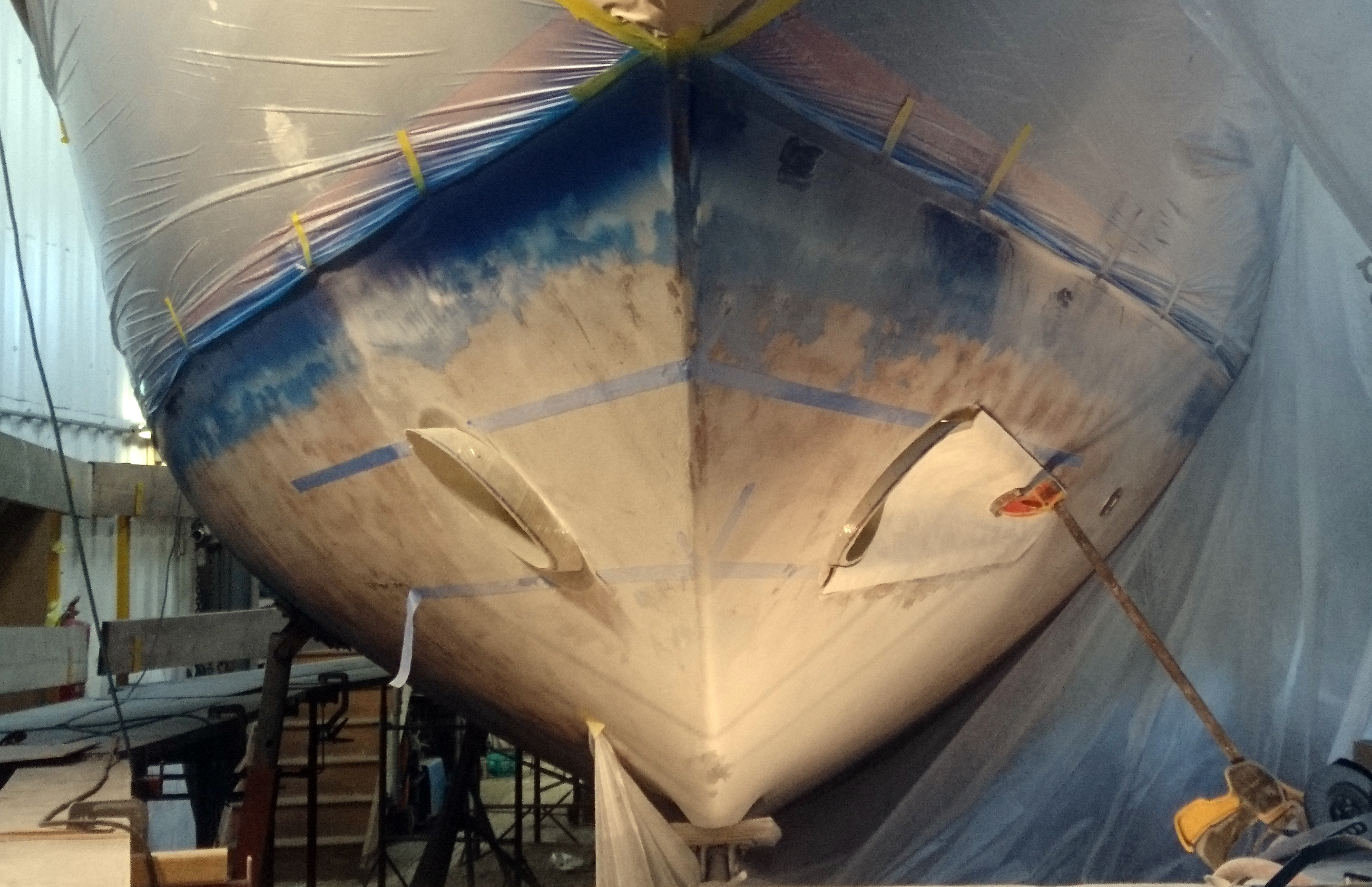
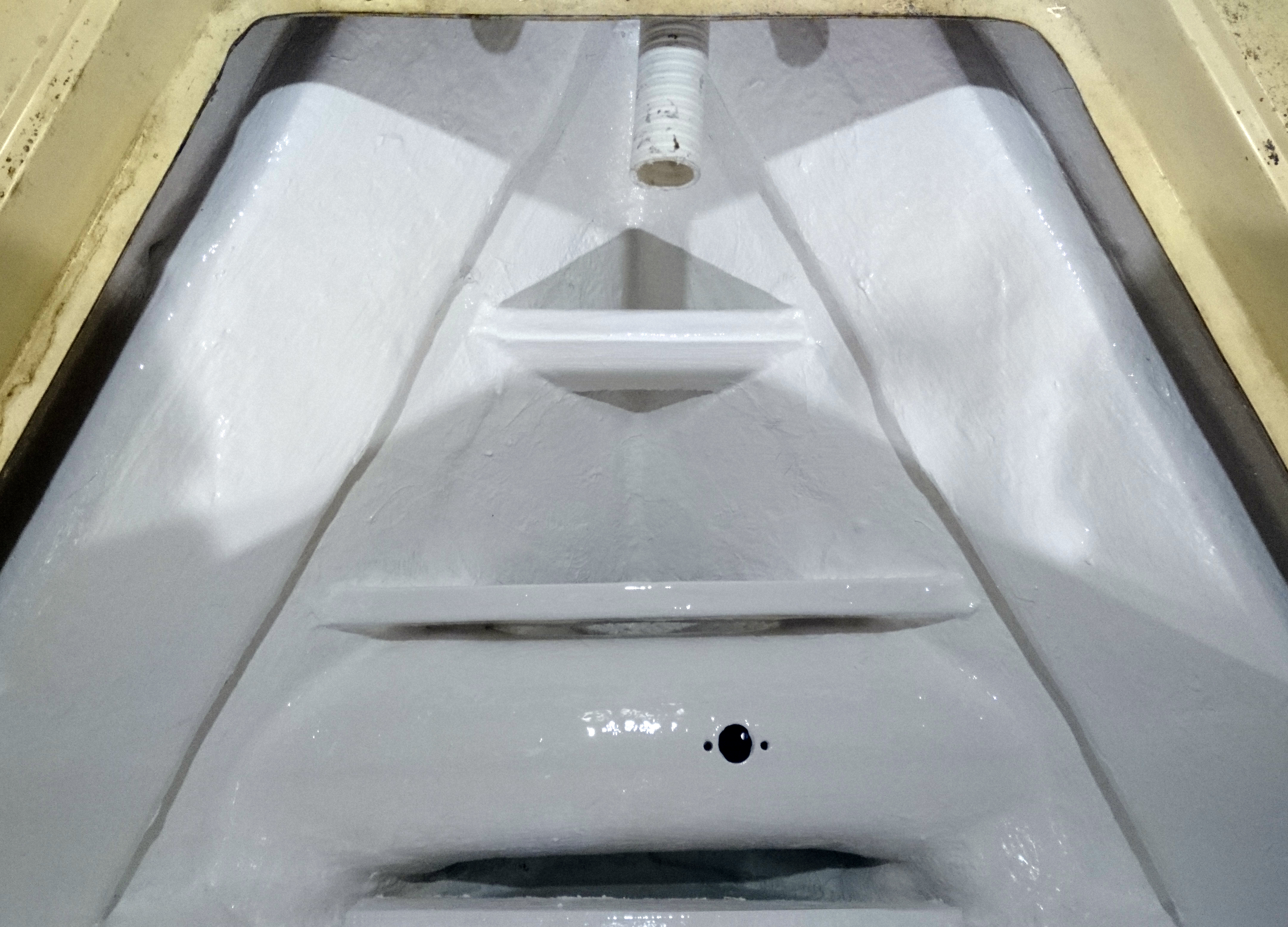
Port almost fair and starboard still rough but from this angle you can see the position of the tube entries are spot on.
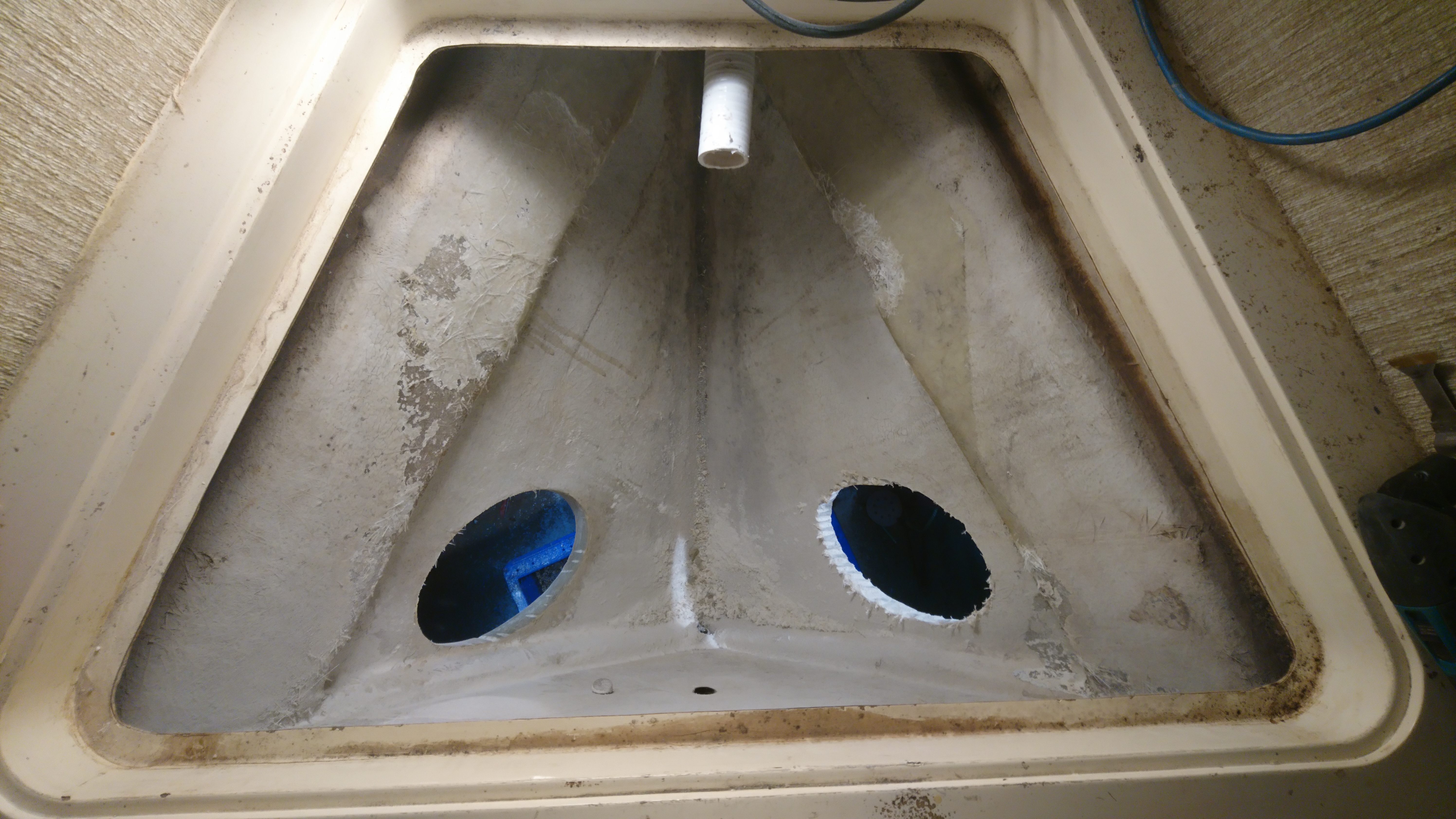
Though the Stb hole appears to be slightly fwd when looked above.
(unless the bulkhead is on the wonk.)
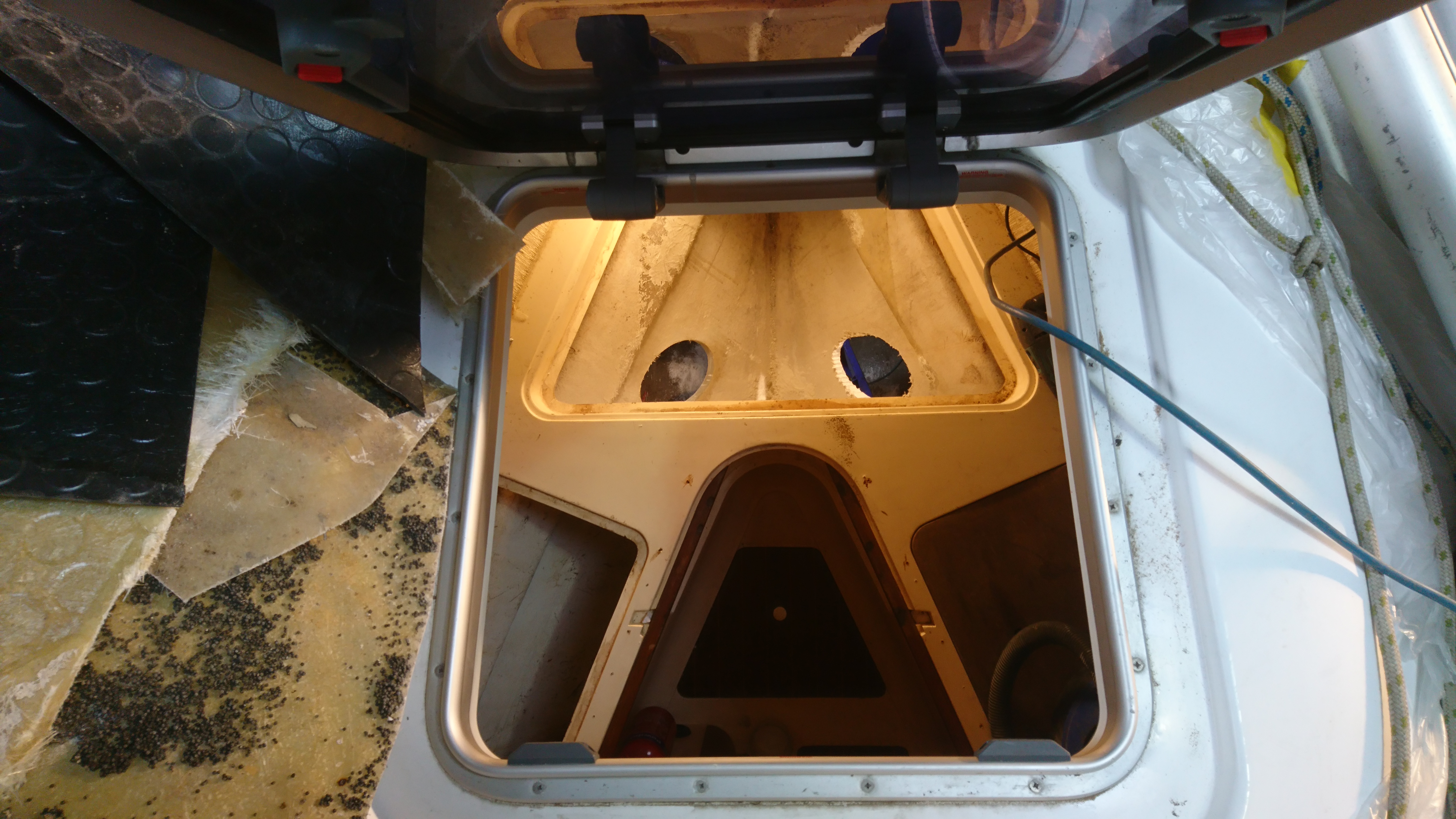
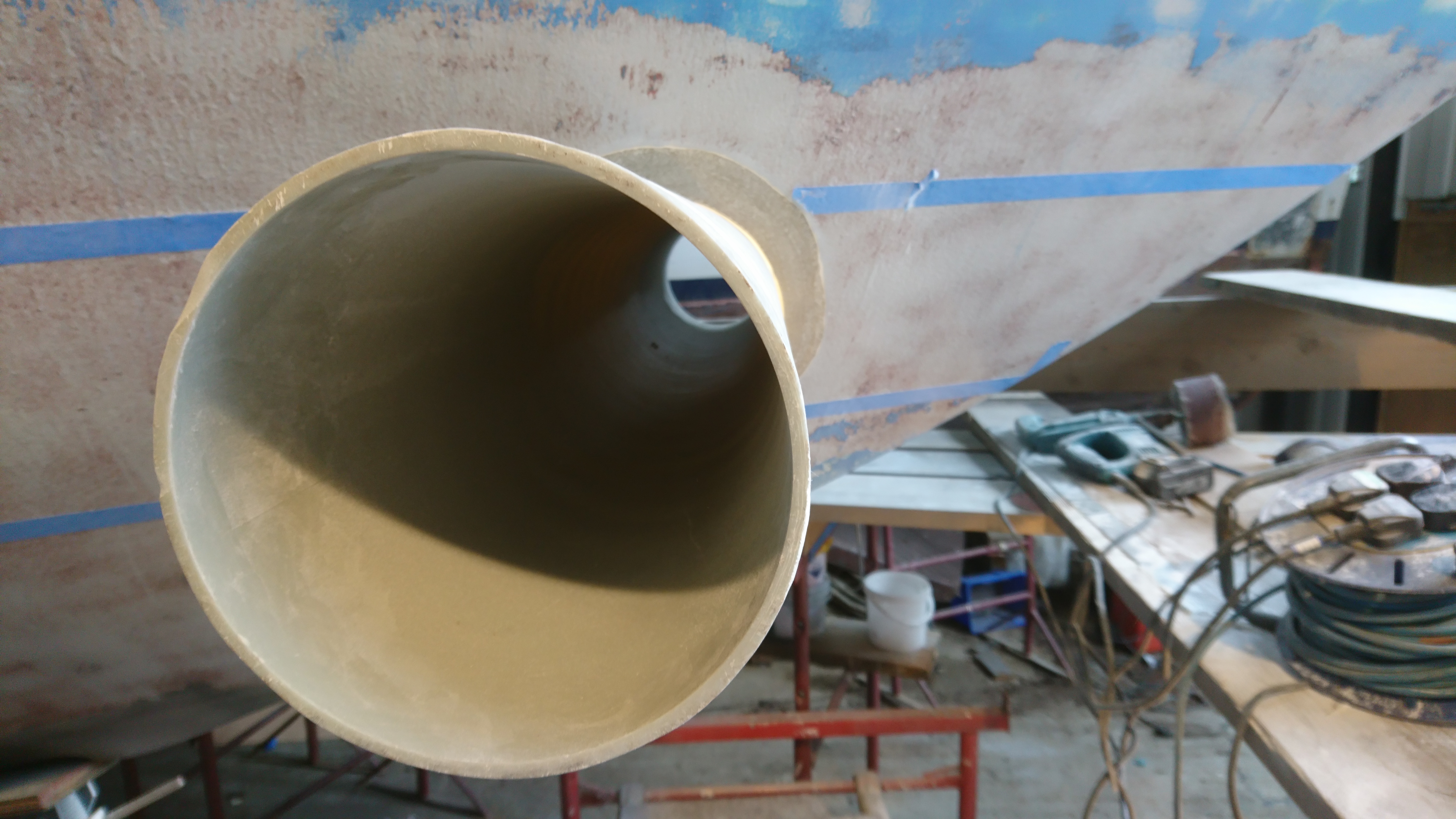
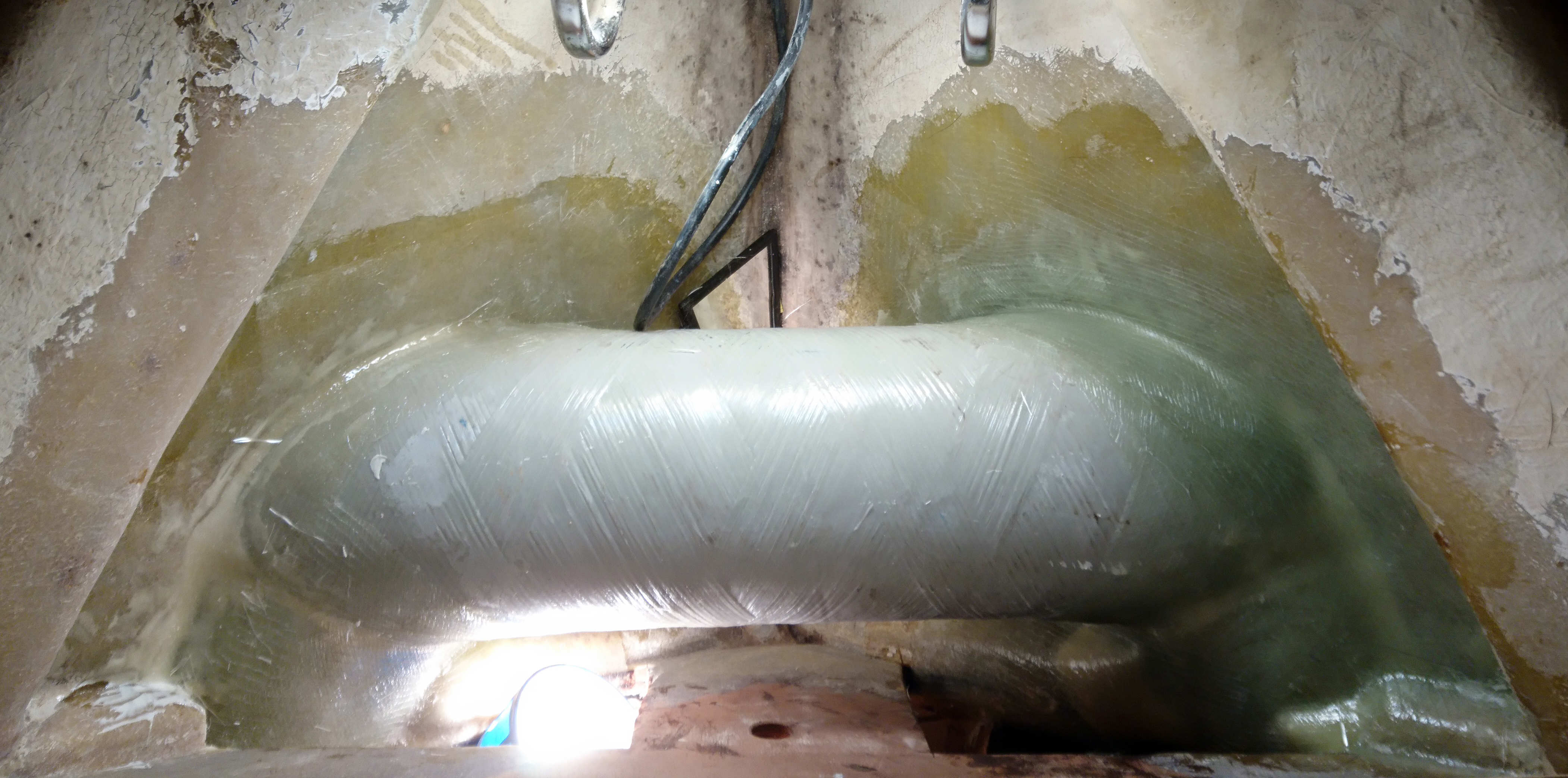
The view through the fwd hatch shows that the tube cannot be any further aft and the motor will have to positioned forward of the tube.
Whilst the tube will be glassed internally to the hull, I like to also glass in externally as well.
So I mark out a 50mm guide which I chamfer and in the process fill shed 2 with dust, which gets everywhere.
Once the chamfer is done it gives me a good 20mm depth of glass externally.
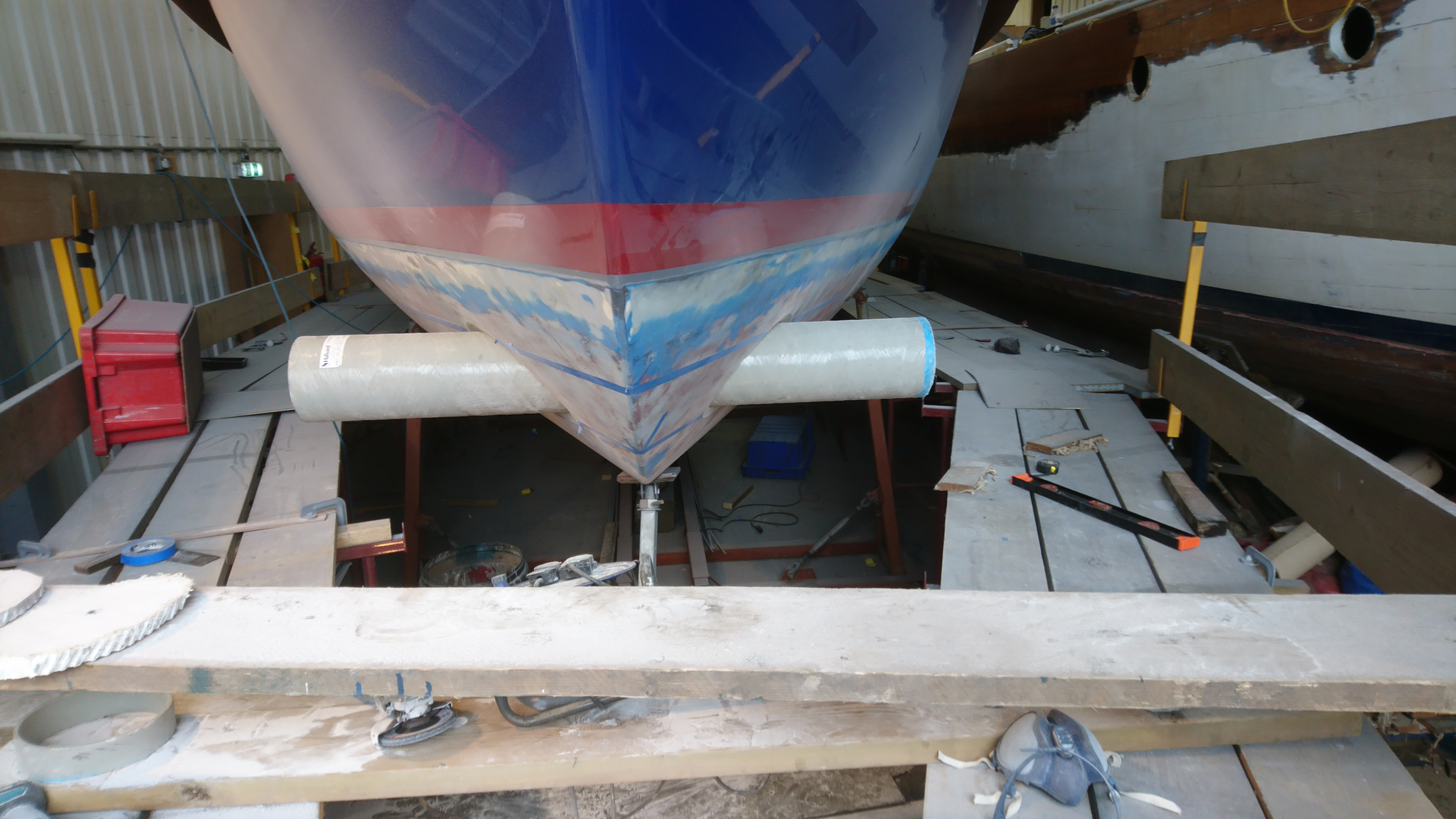
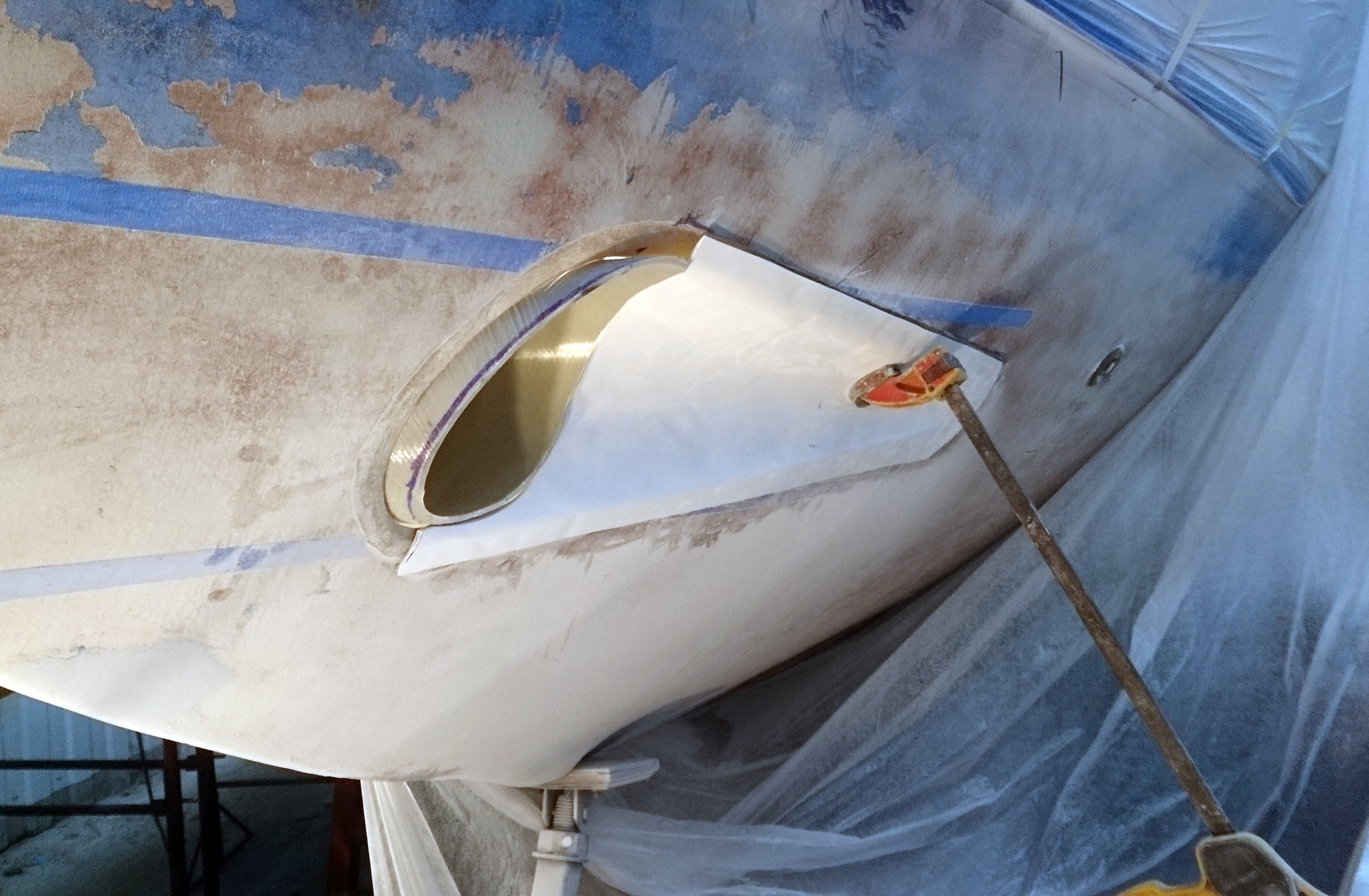
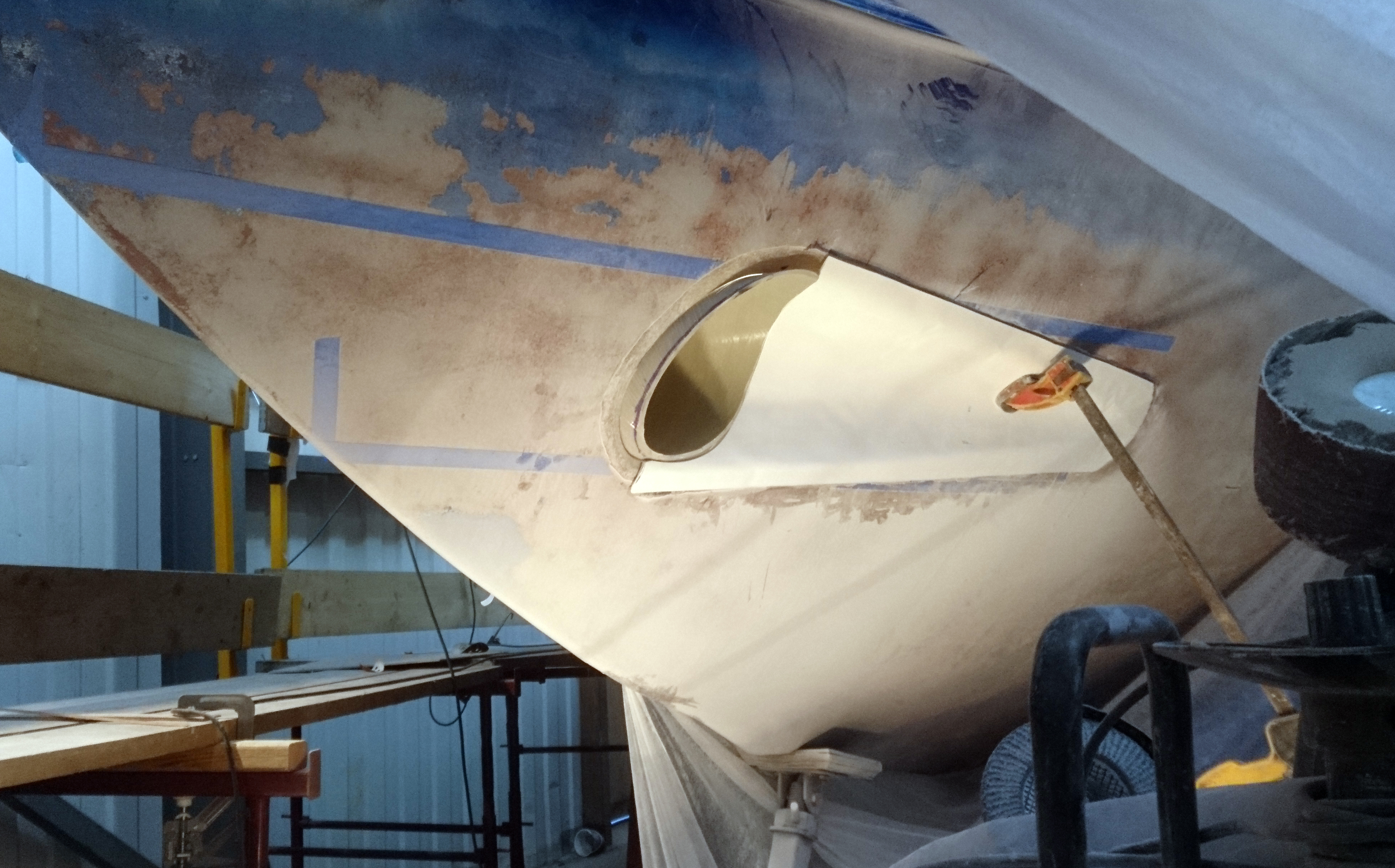
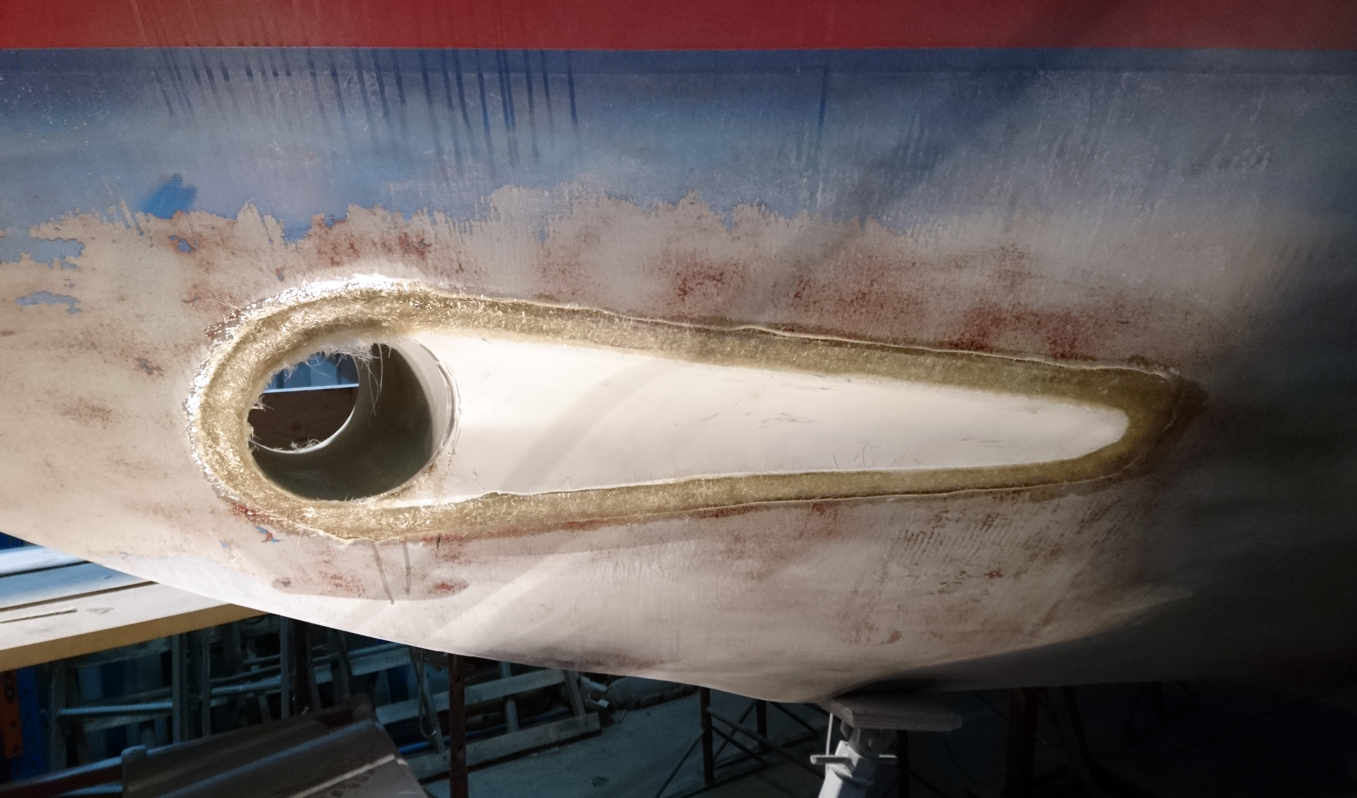
After a little trimming the tube can be test fitted.
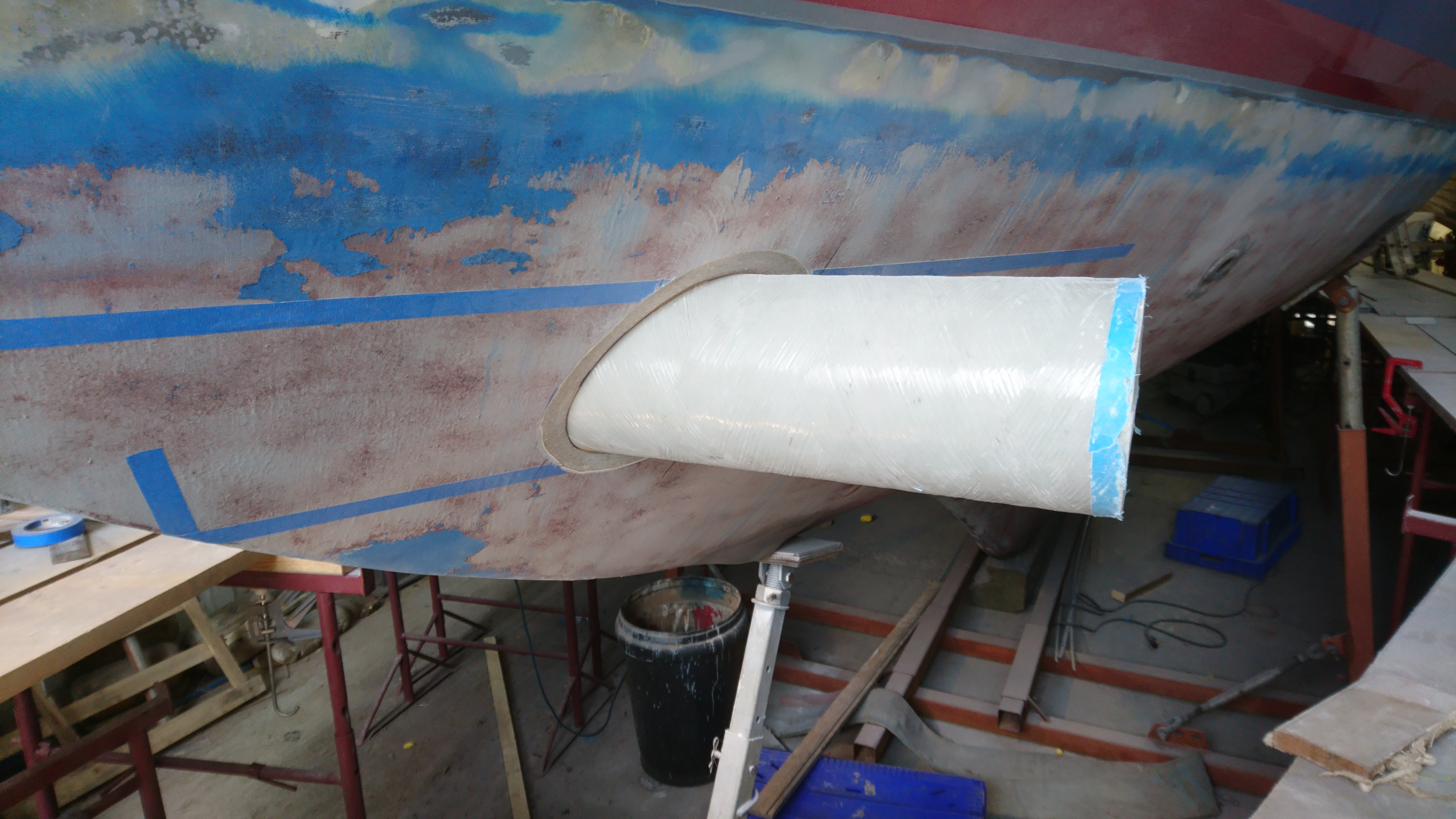
Clearance round the tube is around 2mm.
Inside all looks nice and square.
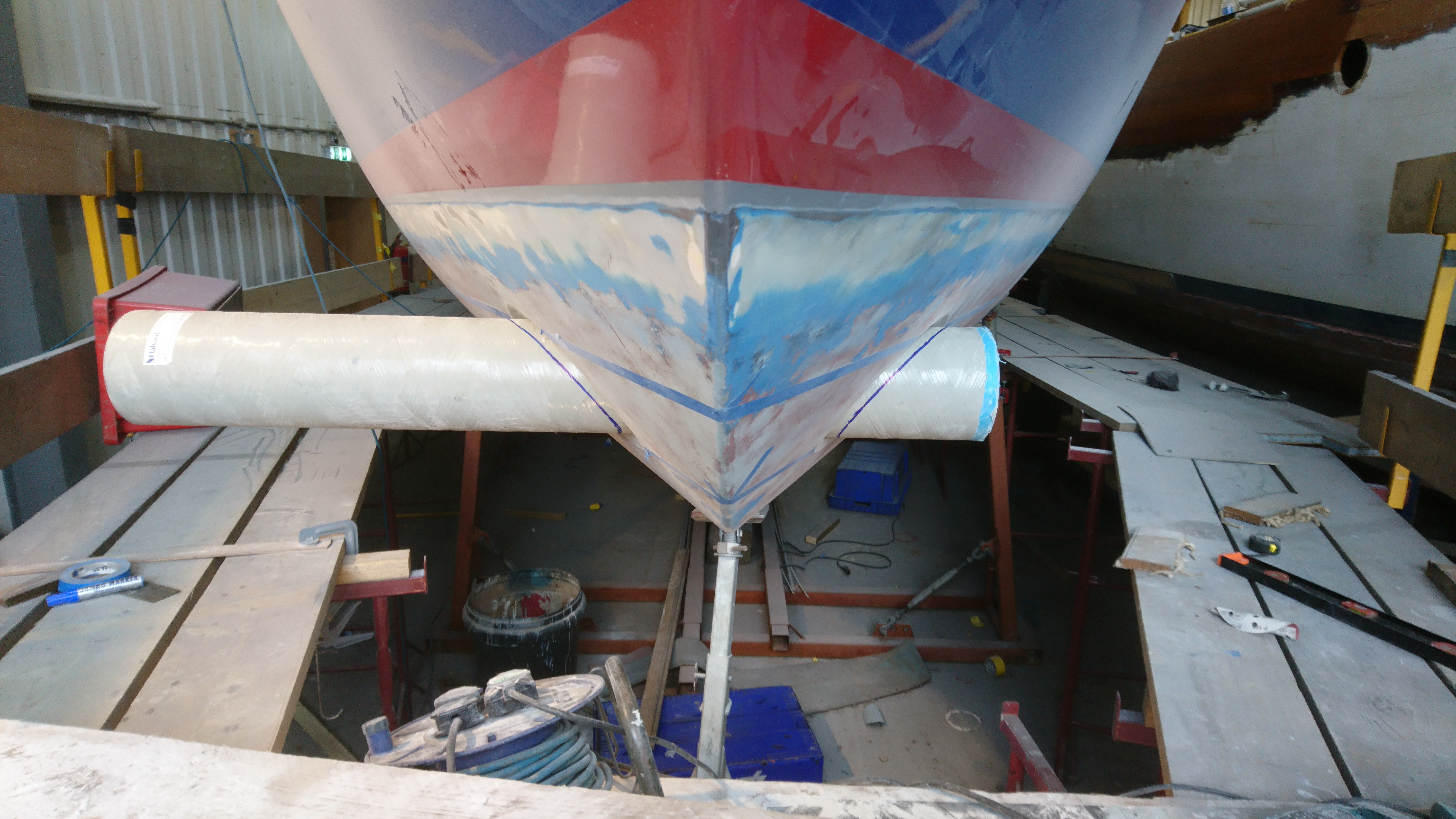
When happy its time to mark the tube for cutting.
I leave around 20mm surplus which I can grind back later after the glassing is done.
With conventional fitting we’d be into glassing but for us its time to look at the scallops.
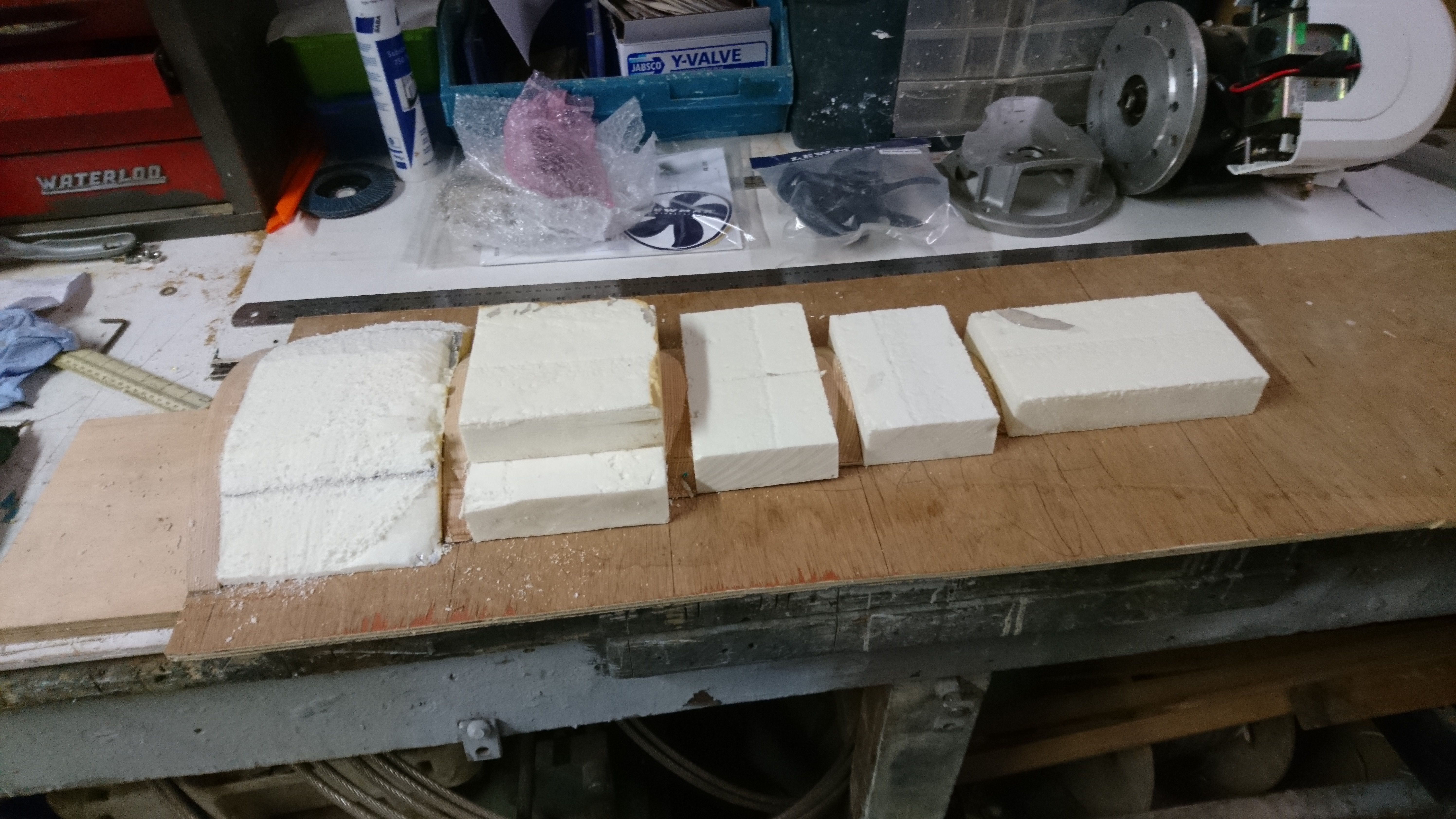
Making a quick mold for the scallops using some gash bits of Kingspan insulation board.
The profile was cut on the wood sections on a bandsaw and then with the blocks of insulation, glued in place with a glue gun.
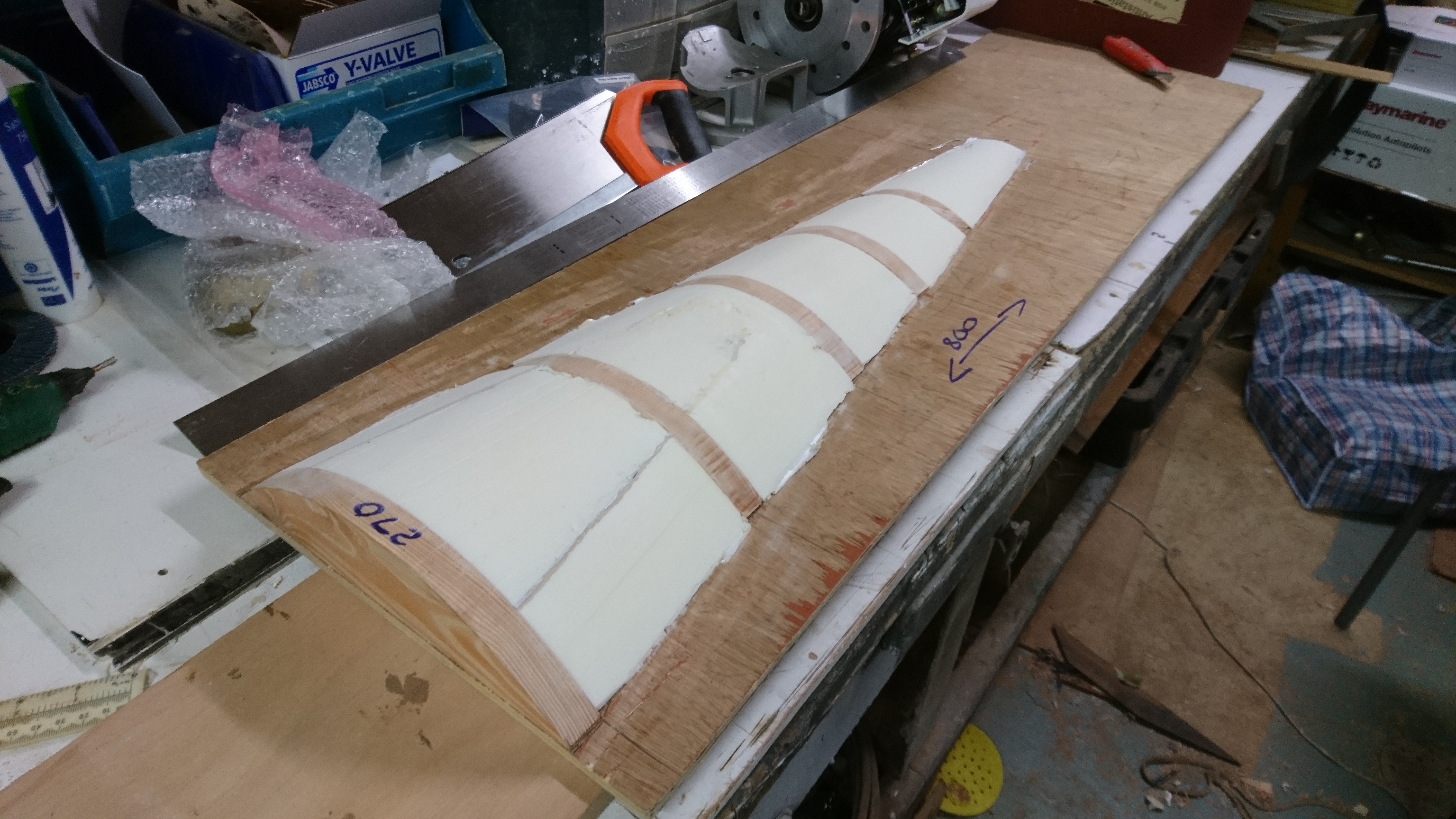
The foam is easy to cut away with a saw blade and a length of 40 grit sandpaper stuck to length of plywood with double sided tape.
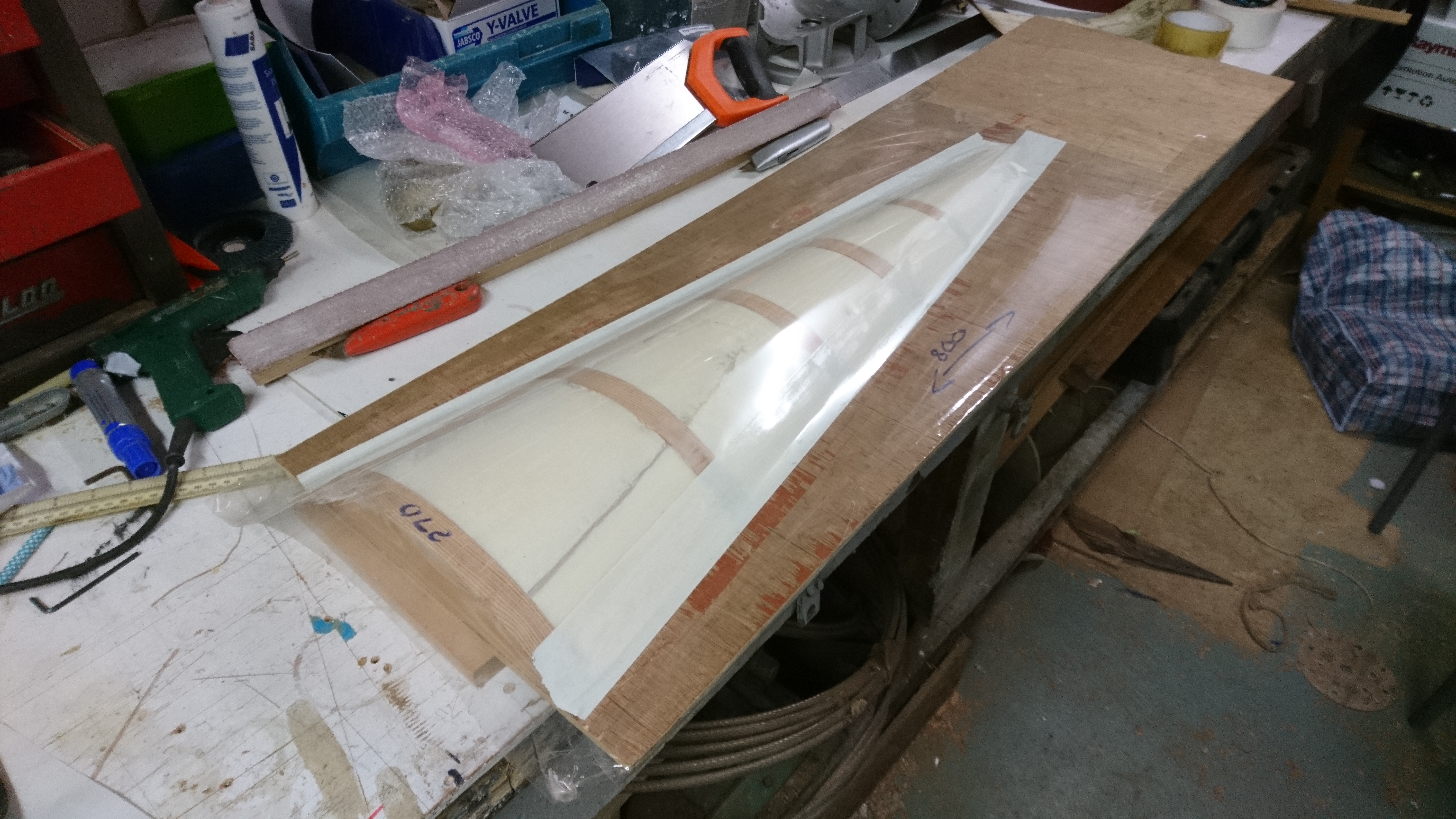
This mold is only wanted to make two scallops so I’ve cheated by laying a sheet of mylar over the foam and stuck down with double sided tape.
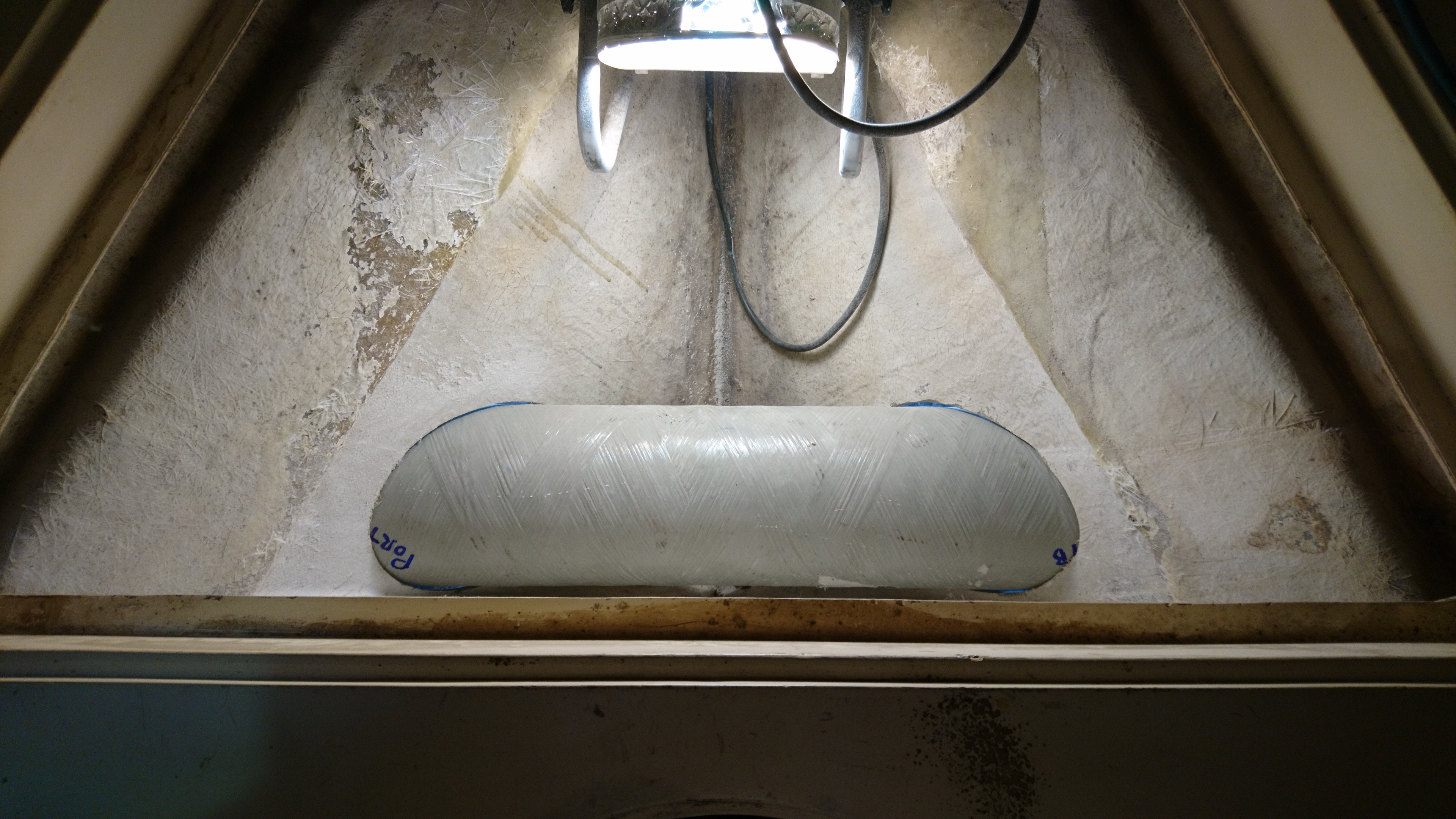
I applied one coat of slipwax polish and it is now ready for Gelcoat.
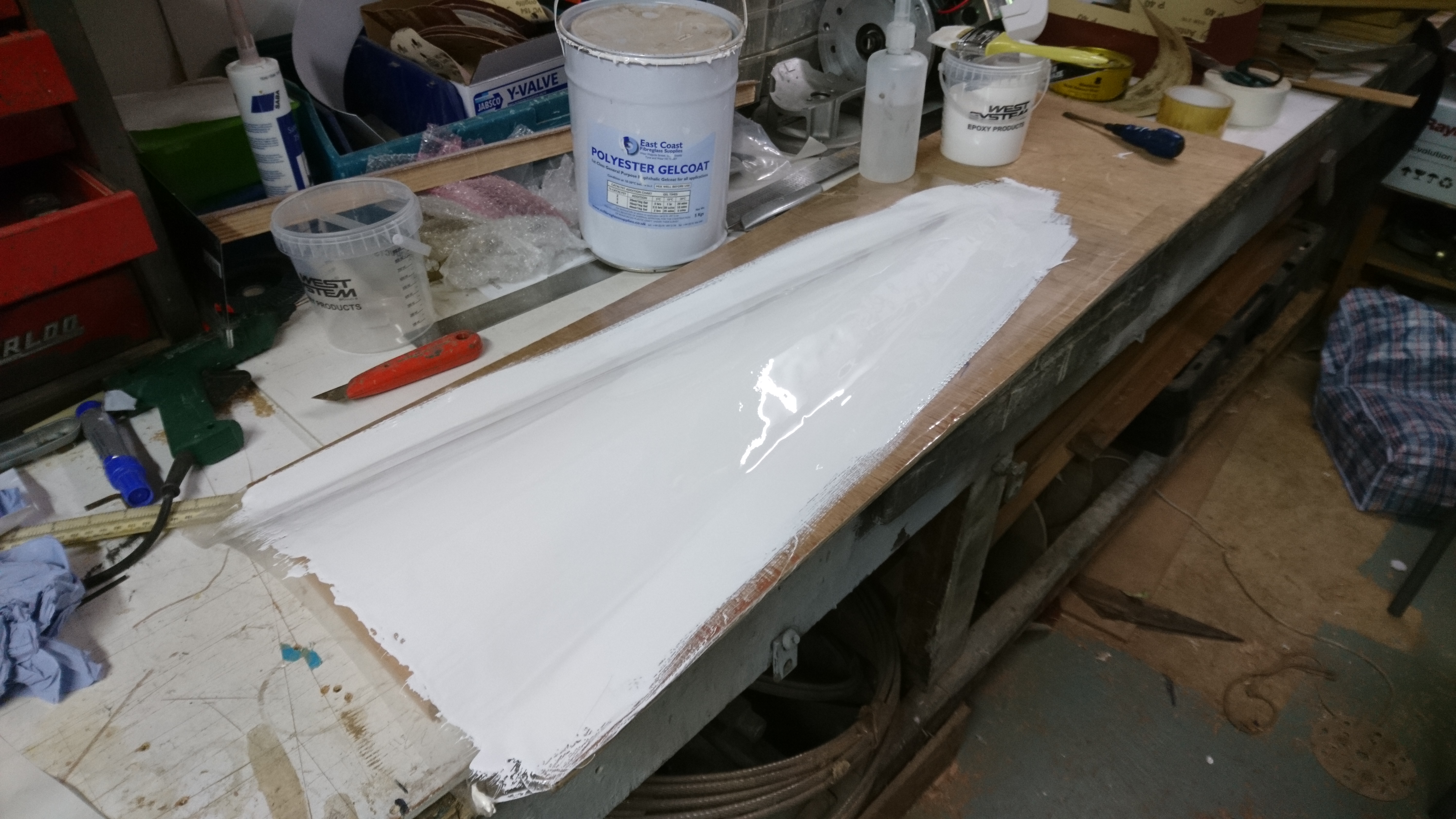
4 coats of gelcoat were applied in between doing other jobs. Roughly one coat every hour with the aid of an Infra Red lamp.
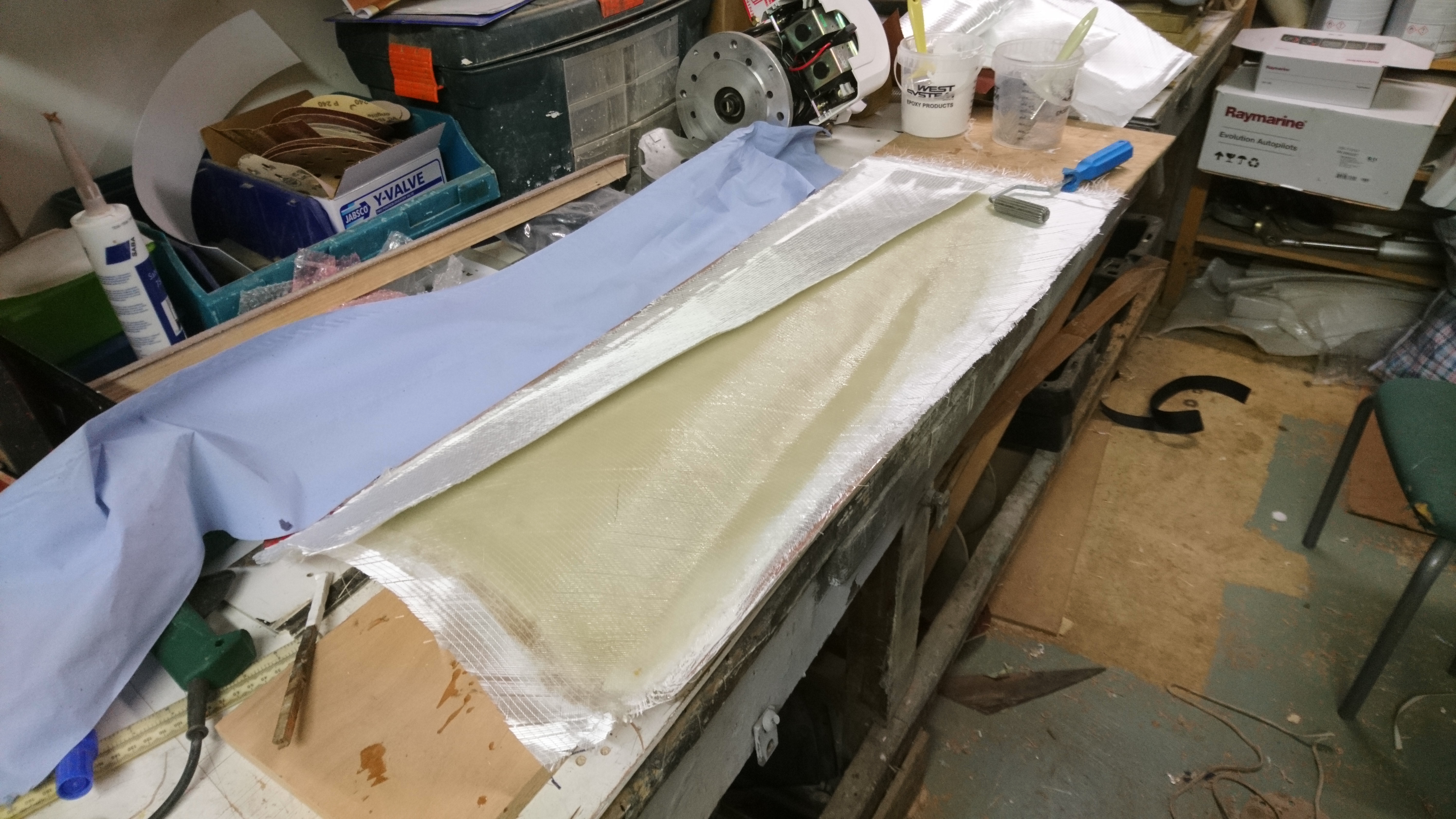
This layup will eventually be quite heavy once glassed into the hull.
Initially though I used 2 layers of 450g csm, 3 layers of 300g biaxial cloth, 2 layers of 500g 150mm wide biaxial tape.
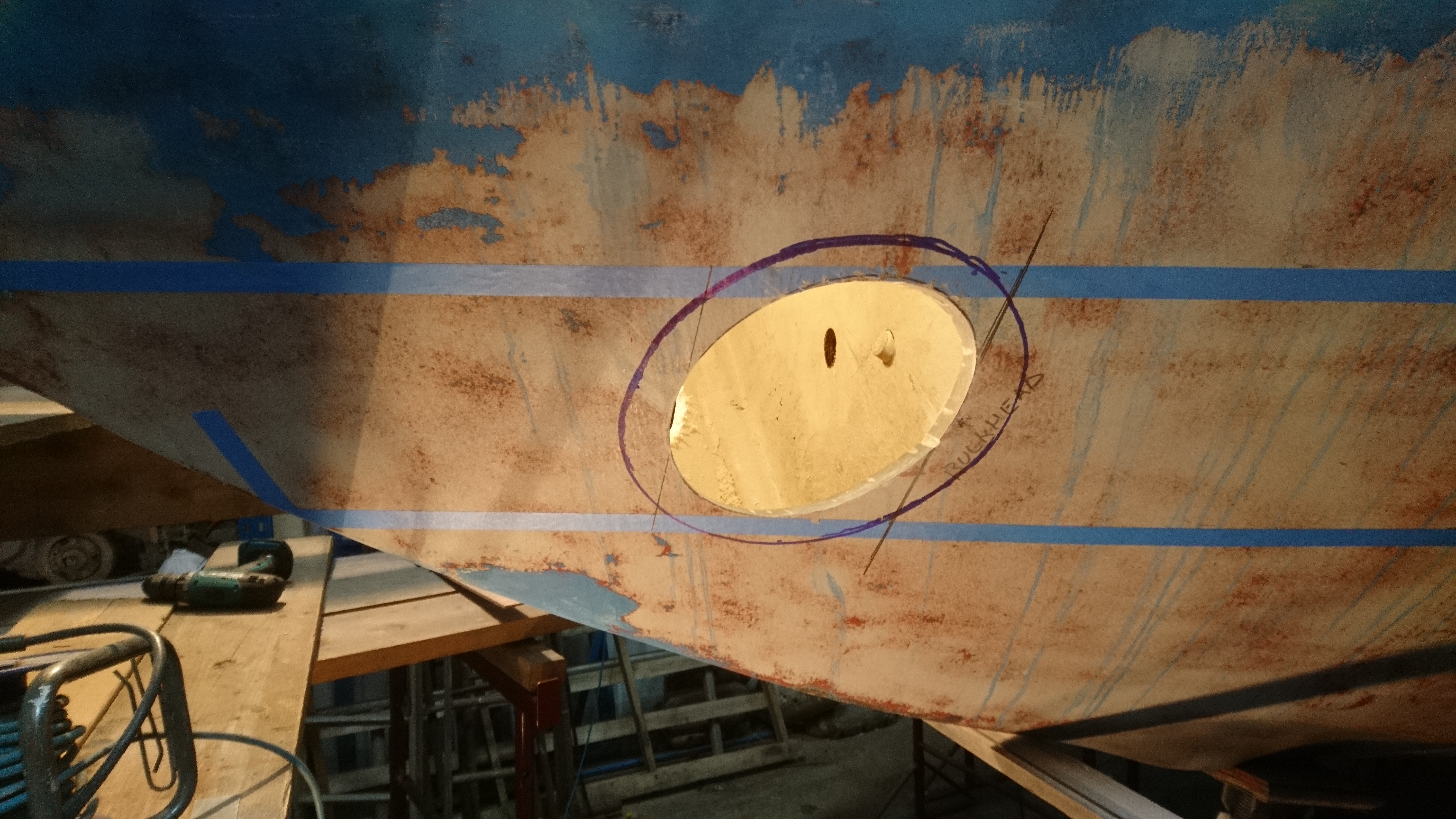
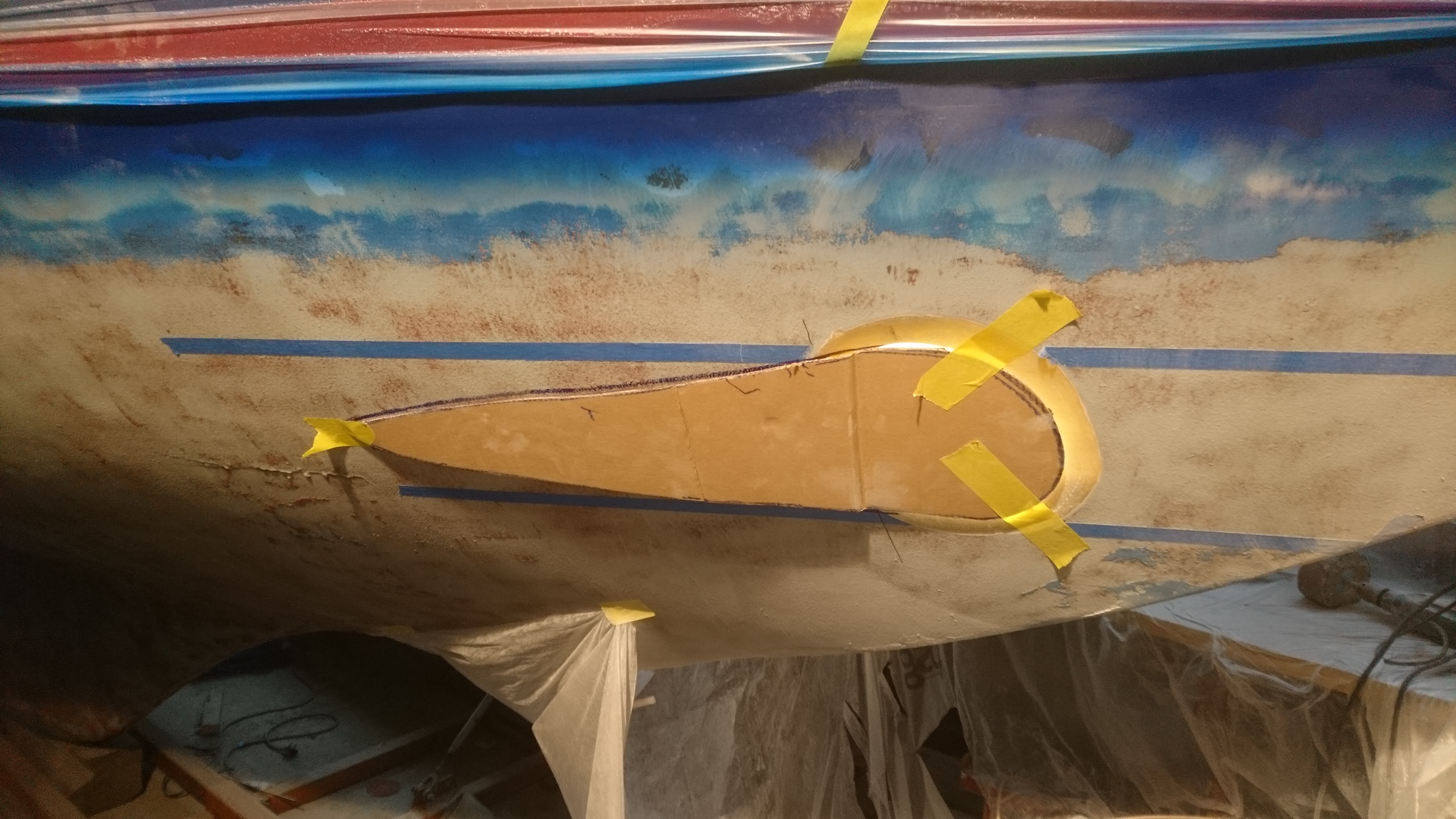
Marking up the cut-out for the scallop.
Check that the owner is not about and then cut a huge hole in the side of the boat.
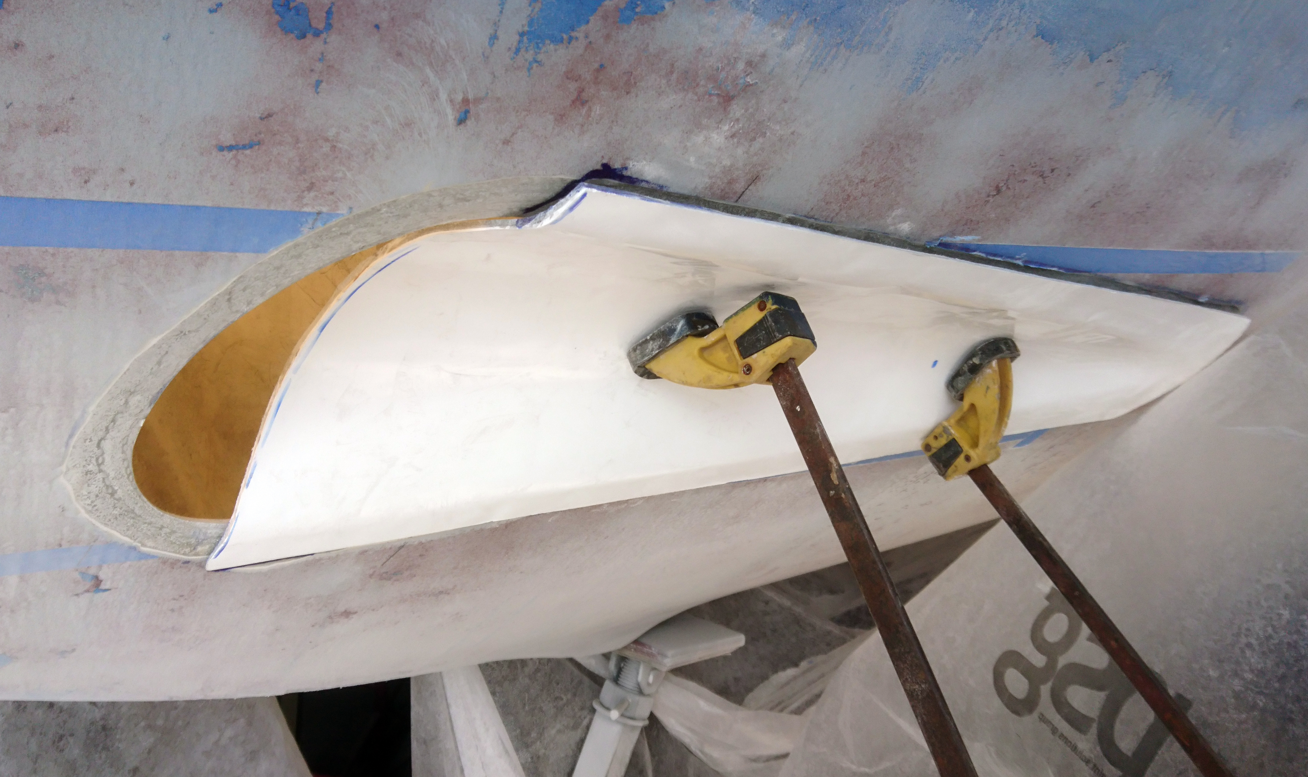
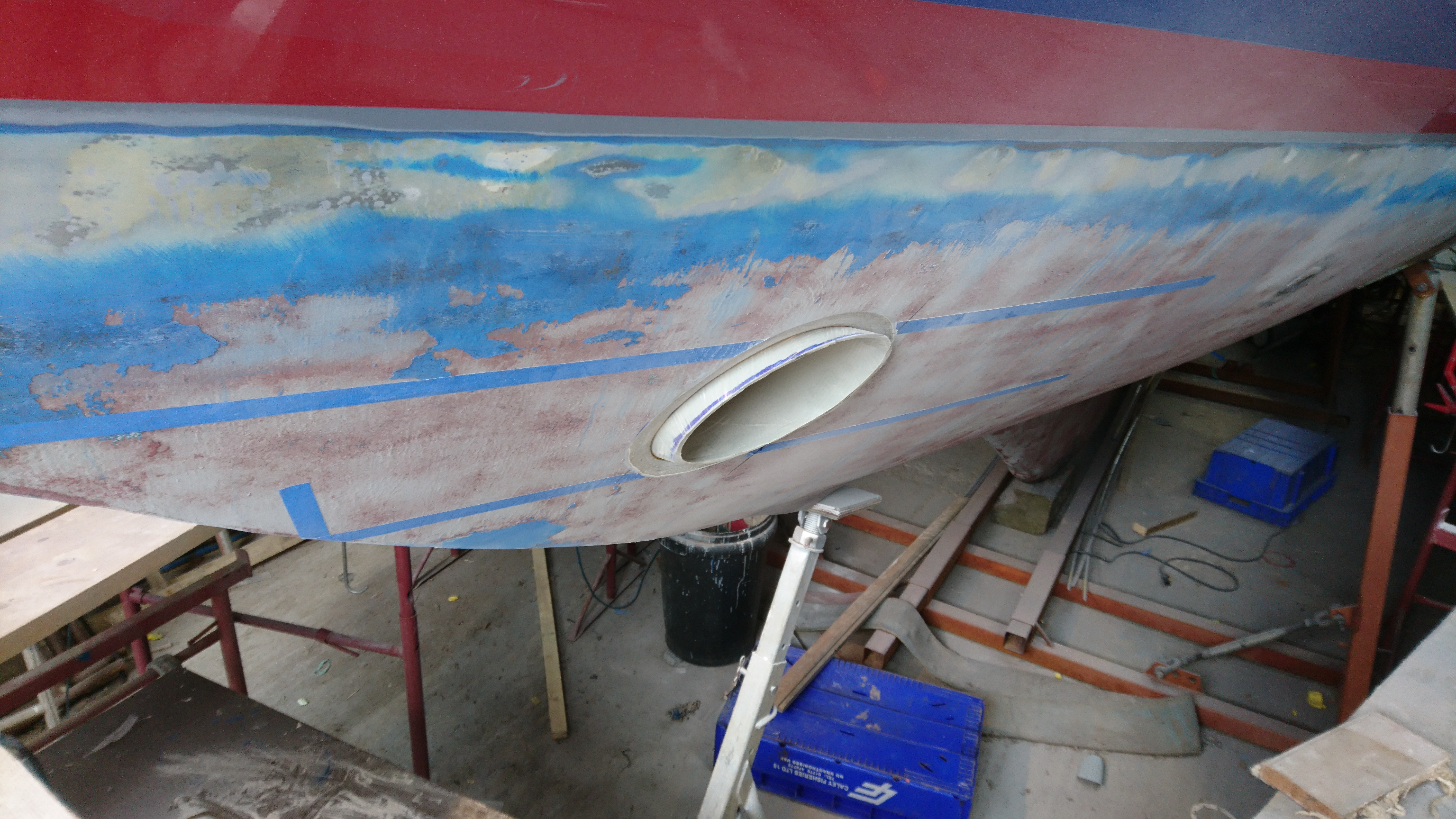
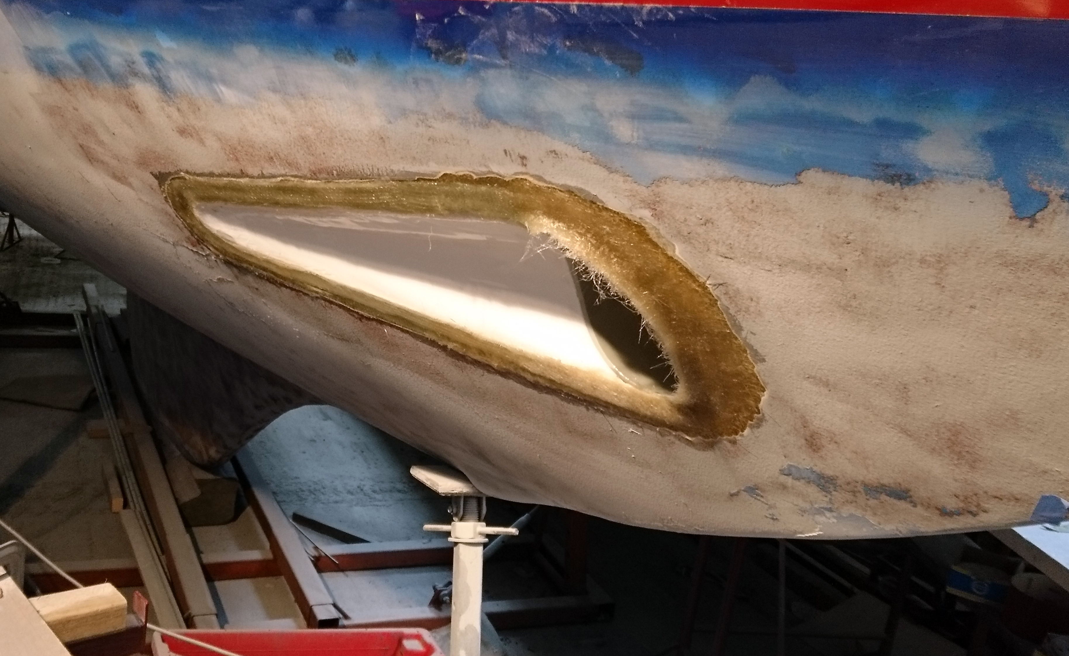
Offering up one of the scallops, the hole is marked and fettled to get a good dry fit.
The tube is inserted, marked and cut to profile.
A visual check from the front shows that the cut out could have been a little bigger at the bottom.
This would mean asymmetric molds rather than the symmetrical one for both.
There’s still an hour or so worth of adjustments using a grinder and flap disc to get a nice joint.
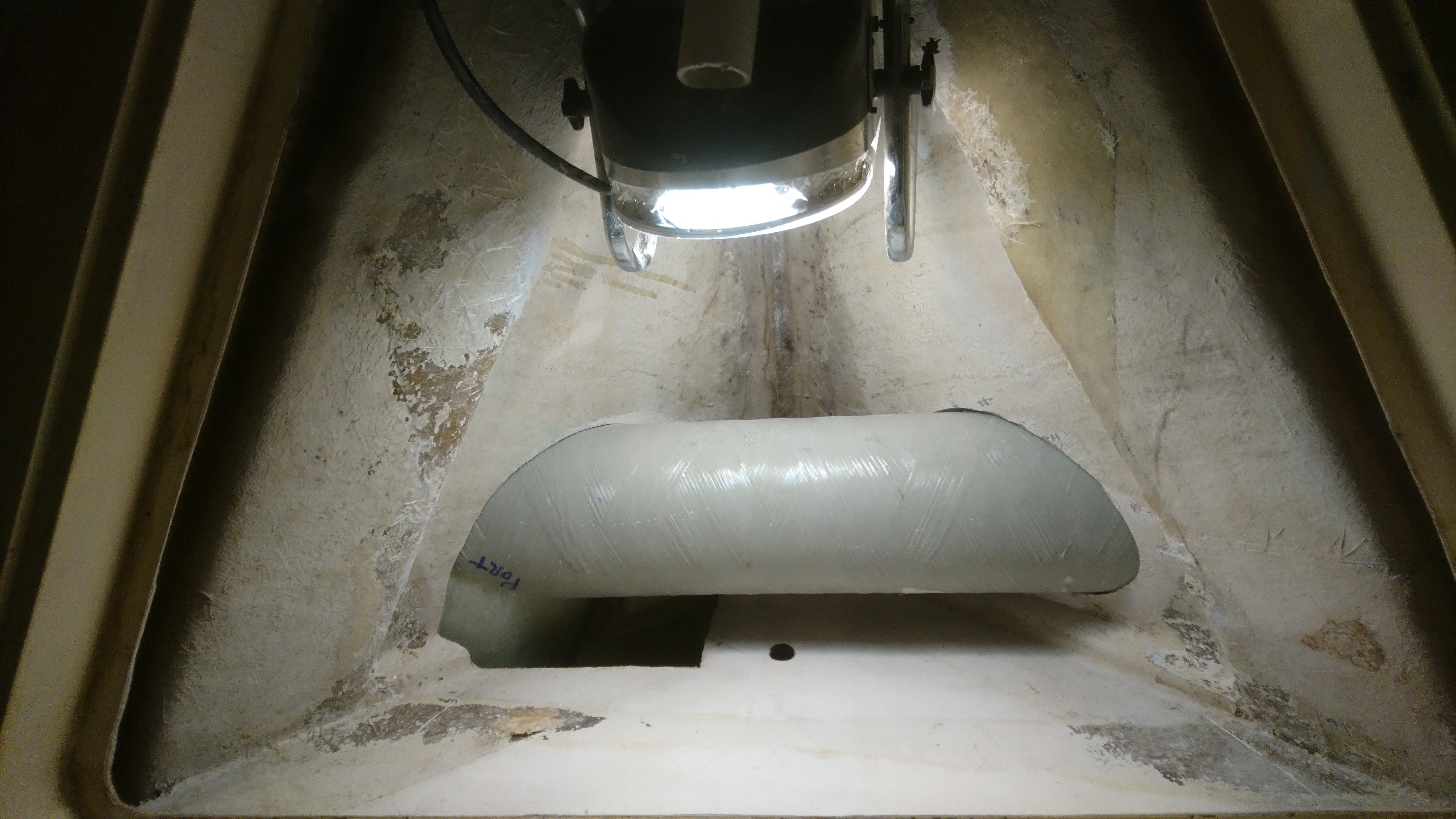
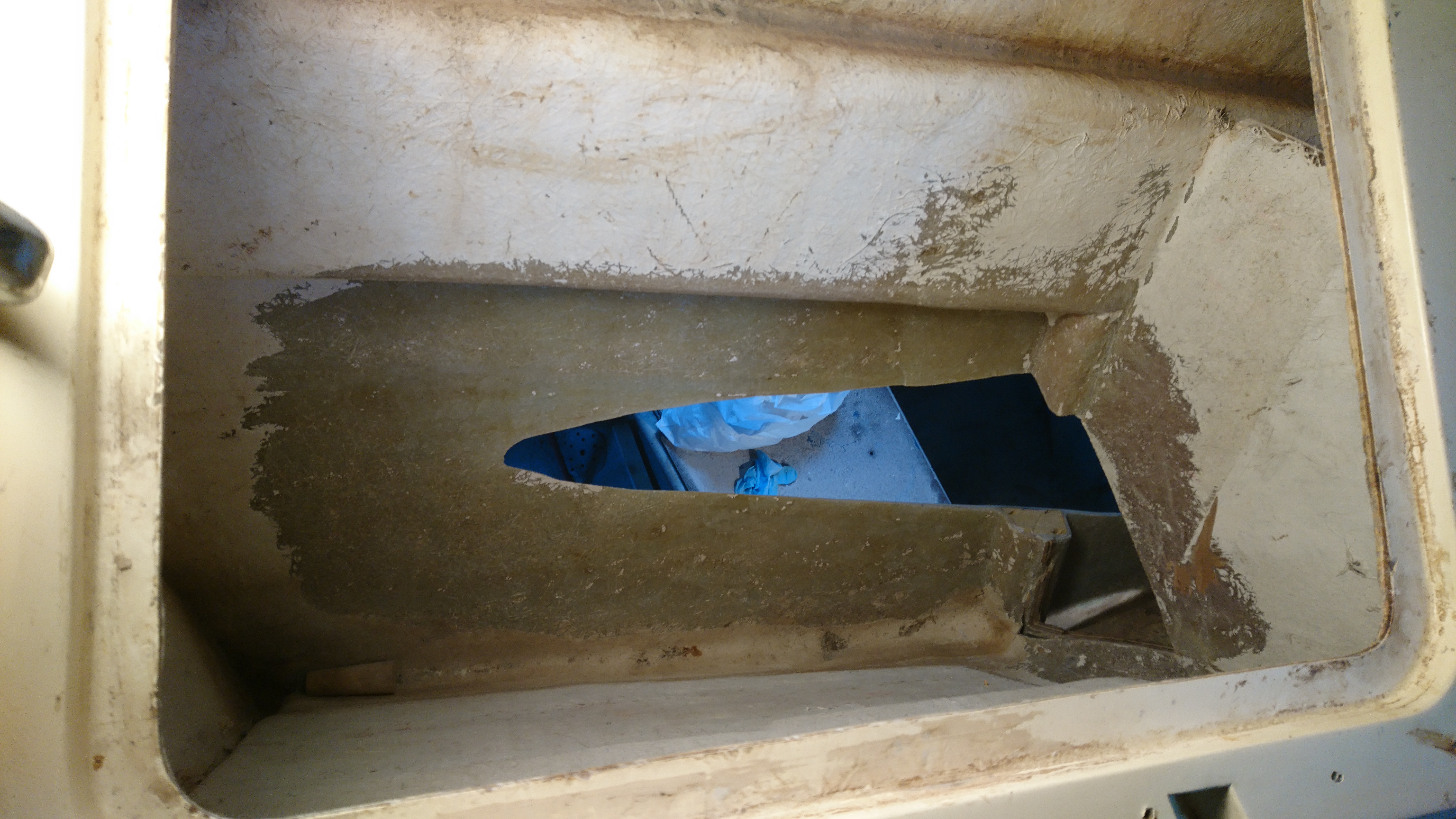
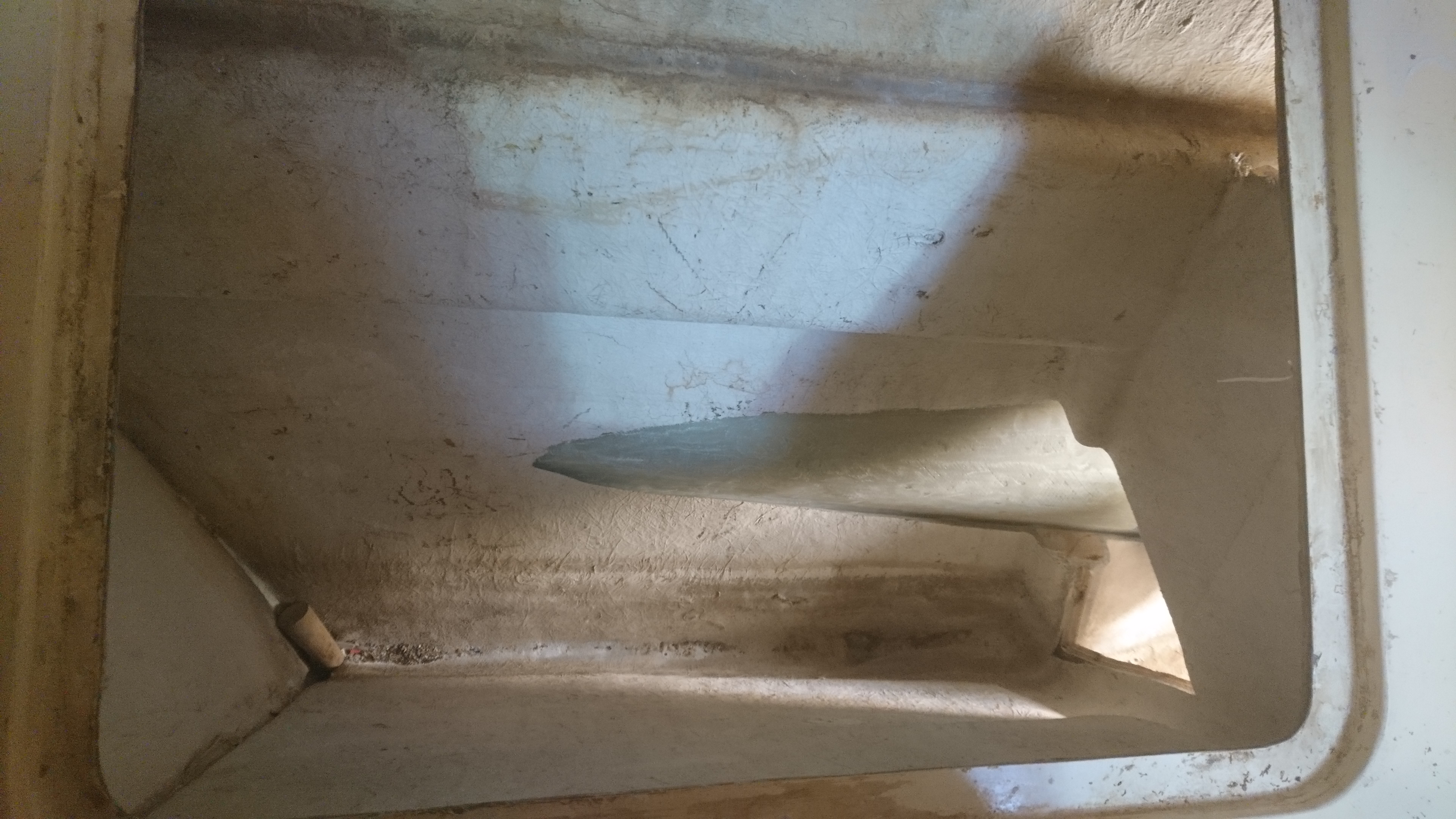
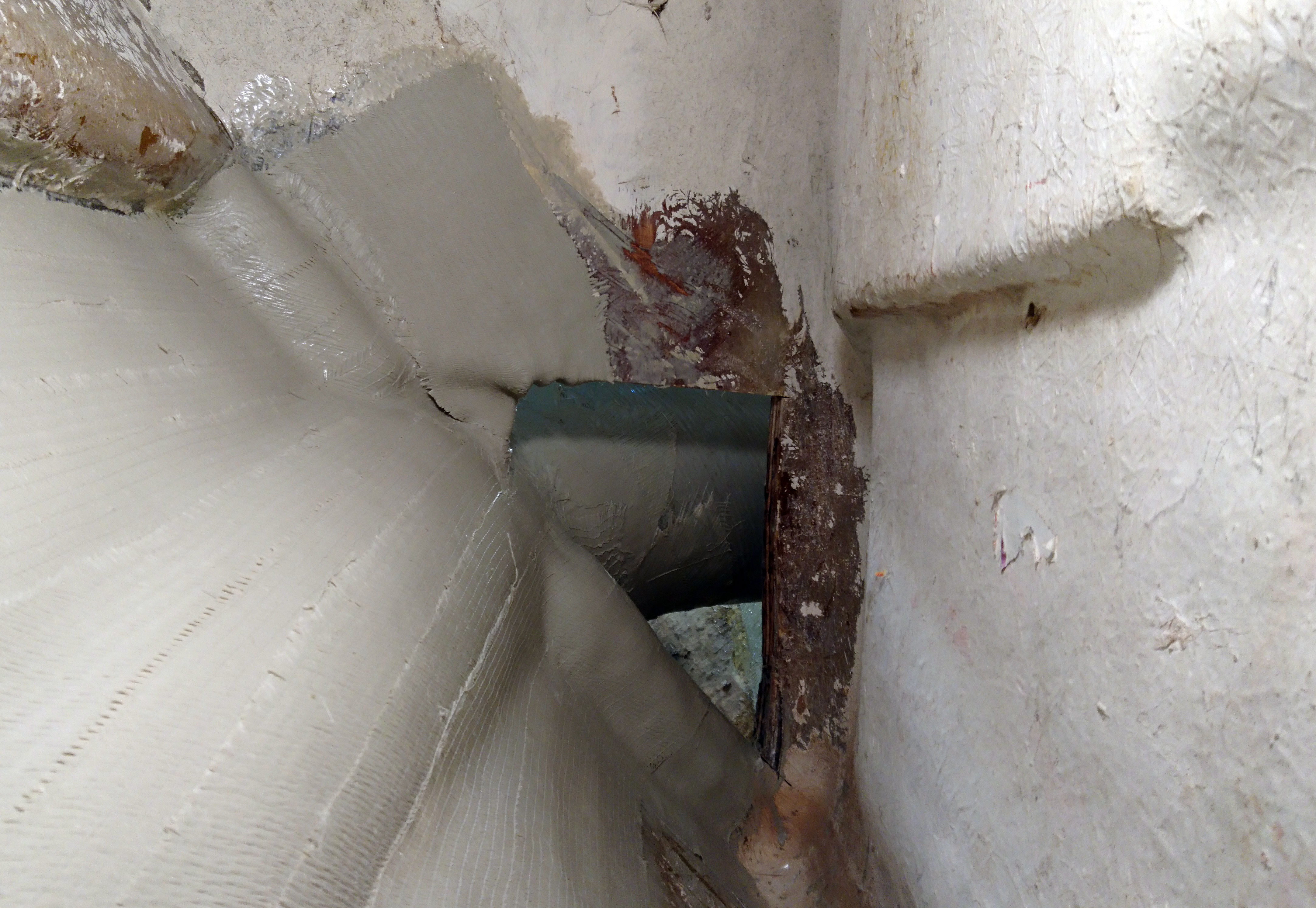
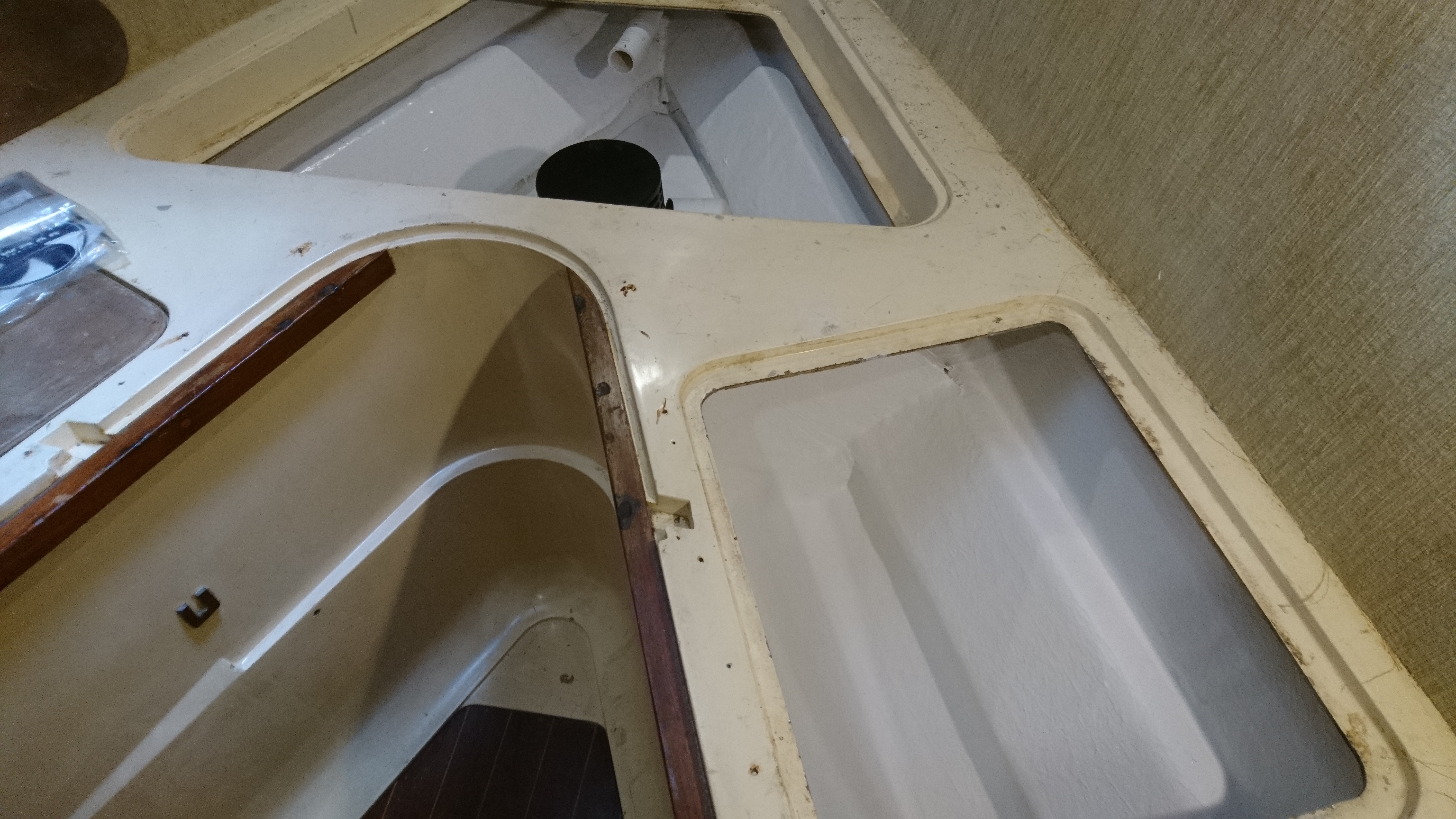
From inside looking down you can see the junction between the tube and the scallop on the port side.
Starboard side is yet to be cut out.
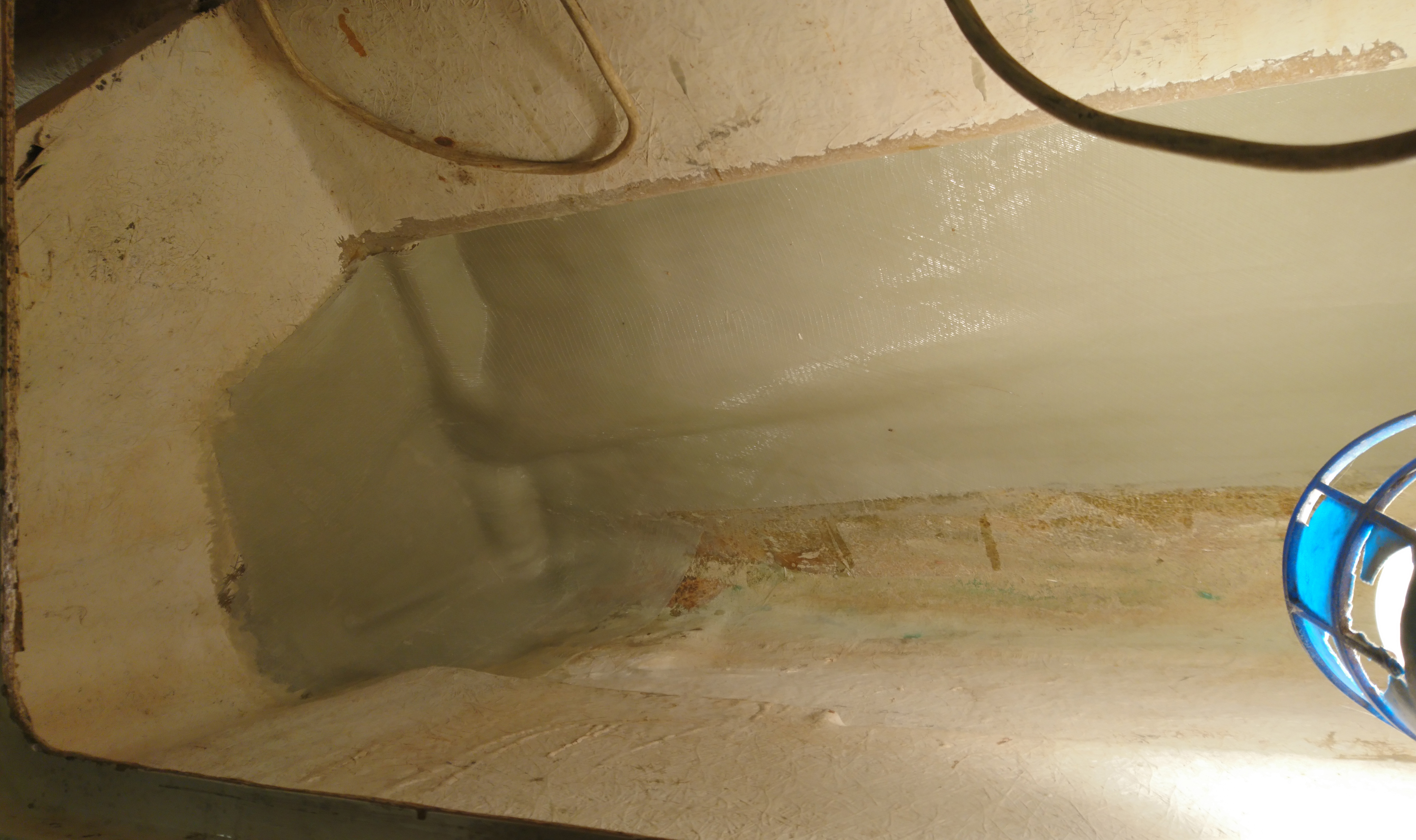
Dry fit of Port side scallop as viewed in the port side bunk locker.
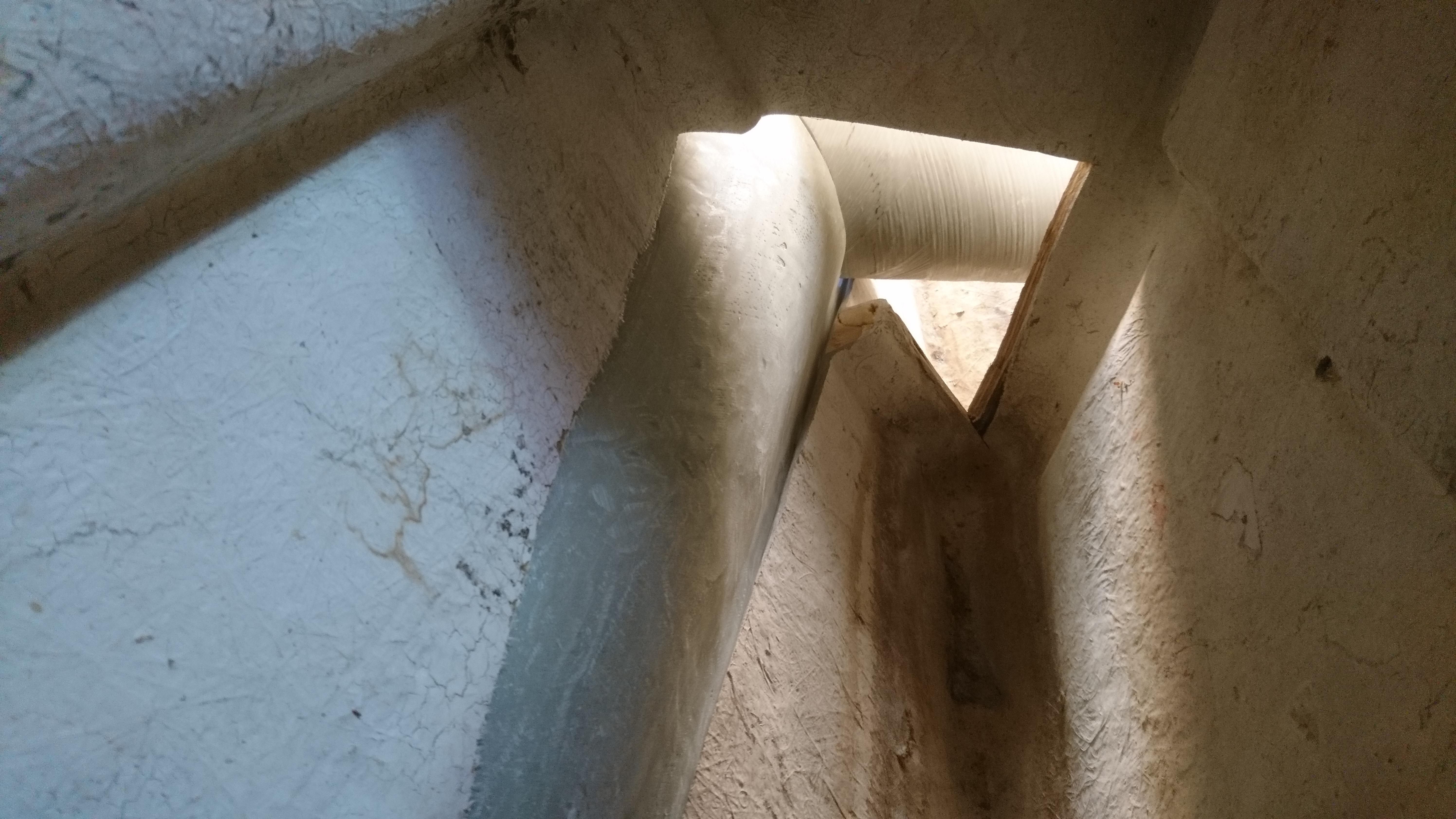
Dry fit of Port side scallop inside the port side bunk locker looking forward.
Using the port side hole as a guide we make a template for the starboard side which speeds the cutting out process up considerably.
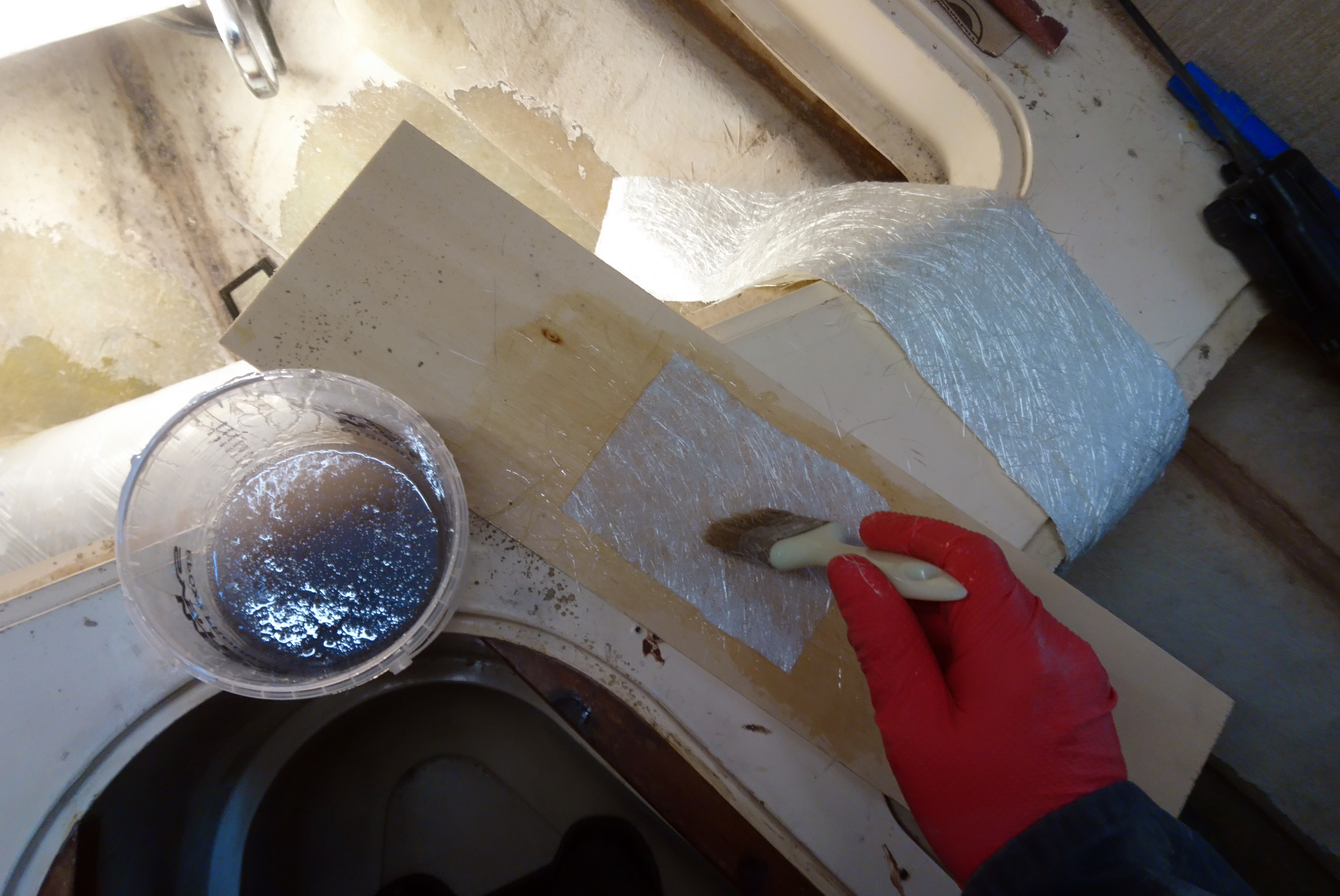
Wet out the glass on a piece of scrap ply before putting it position.
Initial layers are 450gm Chopped Strand as I find it bonds better than cloth.
Pre-wetting out helps getting into tight areas.
Tube partly glassed in using 450g biaxial tape and cloth.
The access holes in the bulkhead can now be filled with 19mm ply and then sheaved to seal the locker once again.
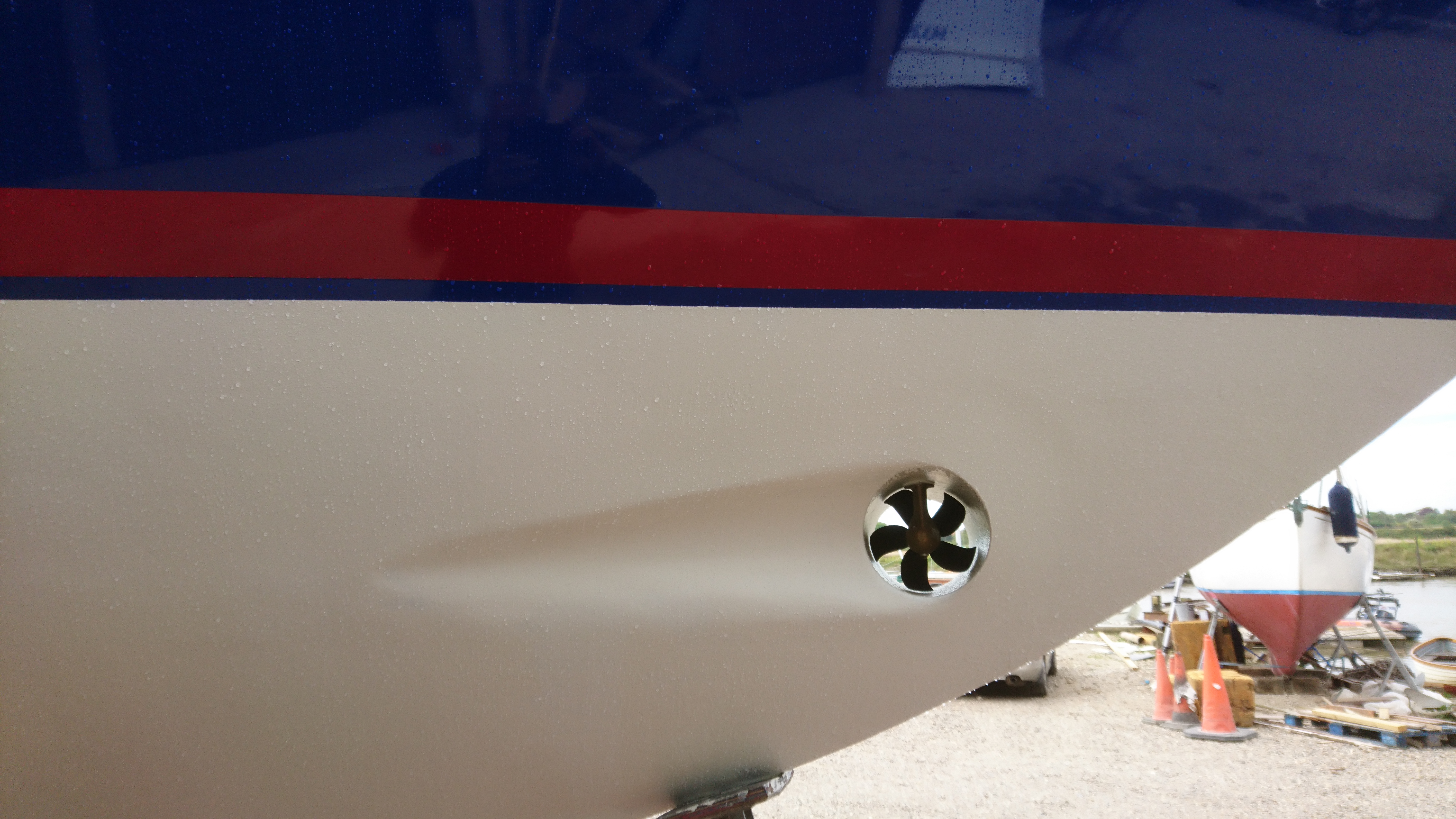
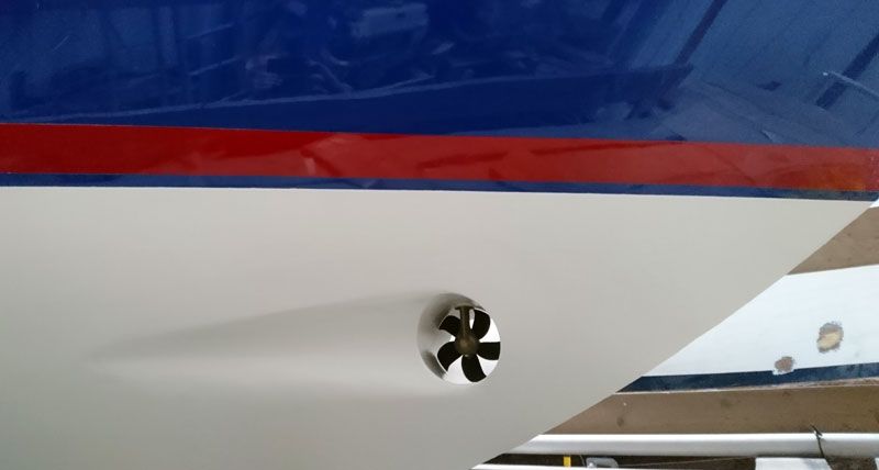
Scallop finished and ready for a gel wash.
Outside the scallop joint is glassed to the hull.
Once glassing is finished its time to fair in.
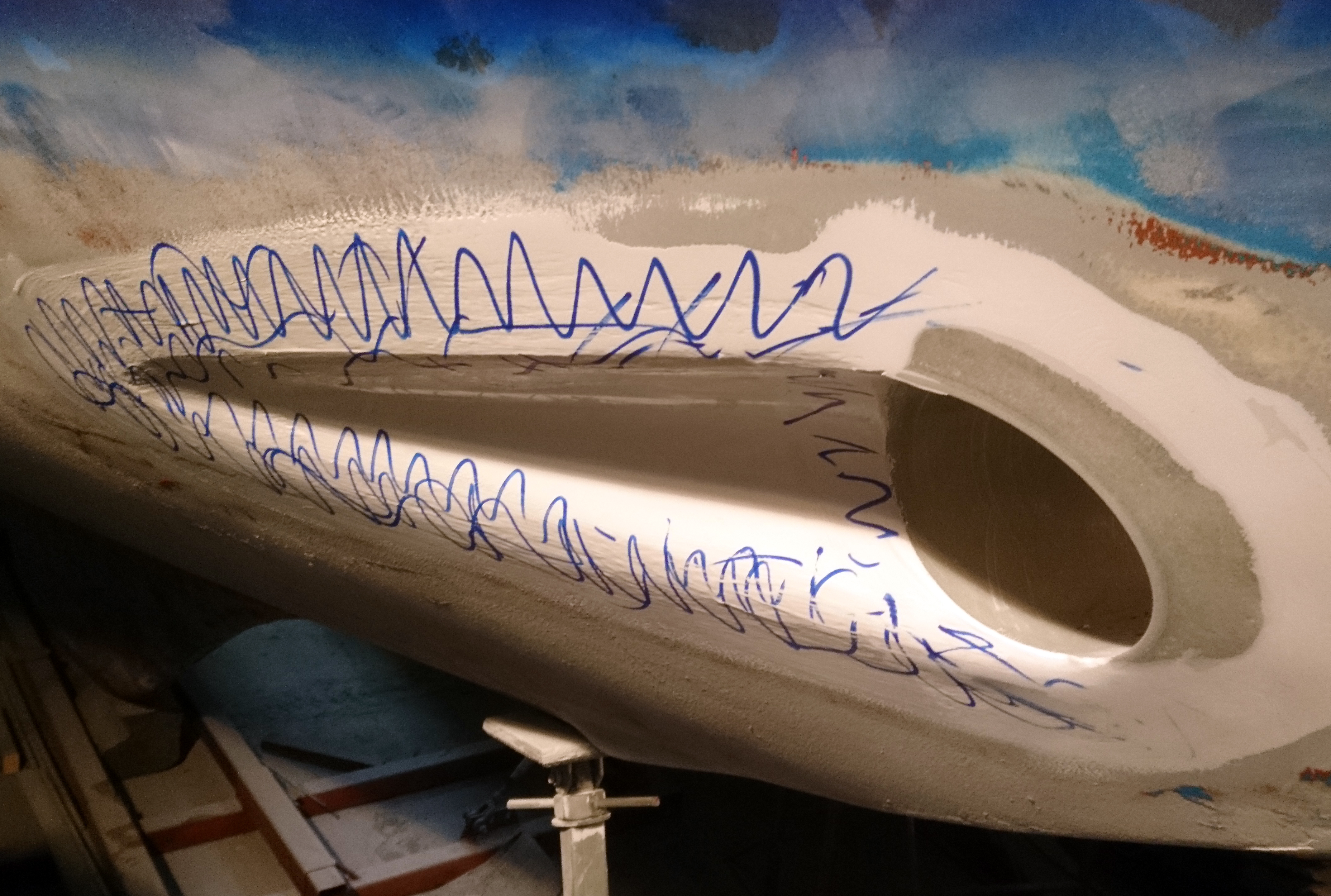
Scribbling with a marker pen and then sanding is a great way to find highs and lows when trying to fair the hull.
This job eats 40 grit sandpaper discs, you can easily use a full box of 50 on a boat of this size.
Testing the position of the saddle and motor prior to marking and drill the gearbox holes.
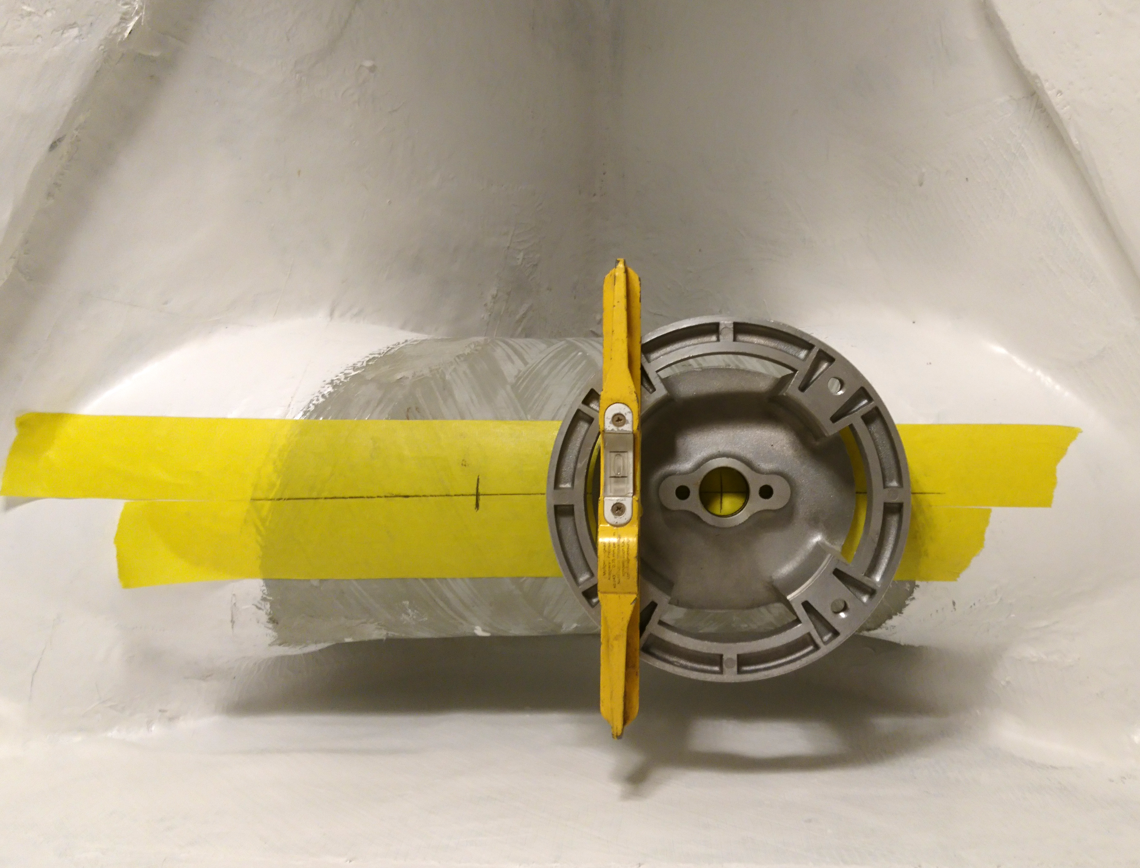
Using tape on the tube makes it easier to see the positional marks before drilling.
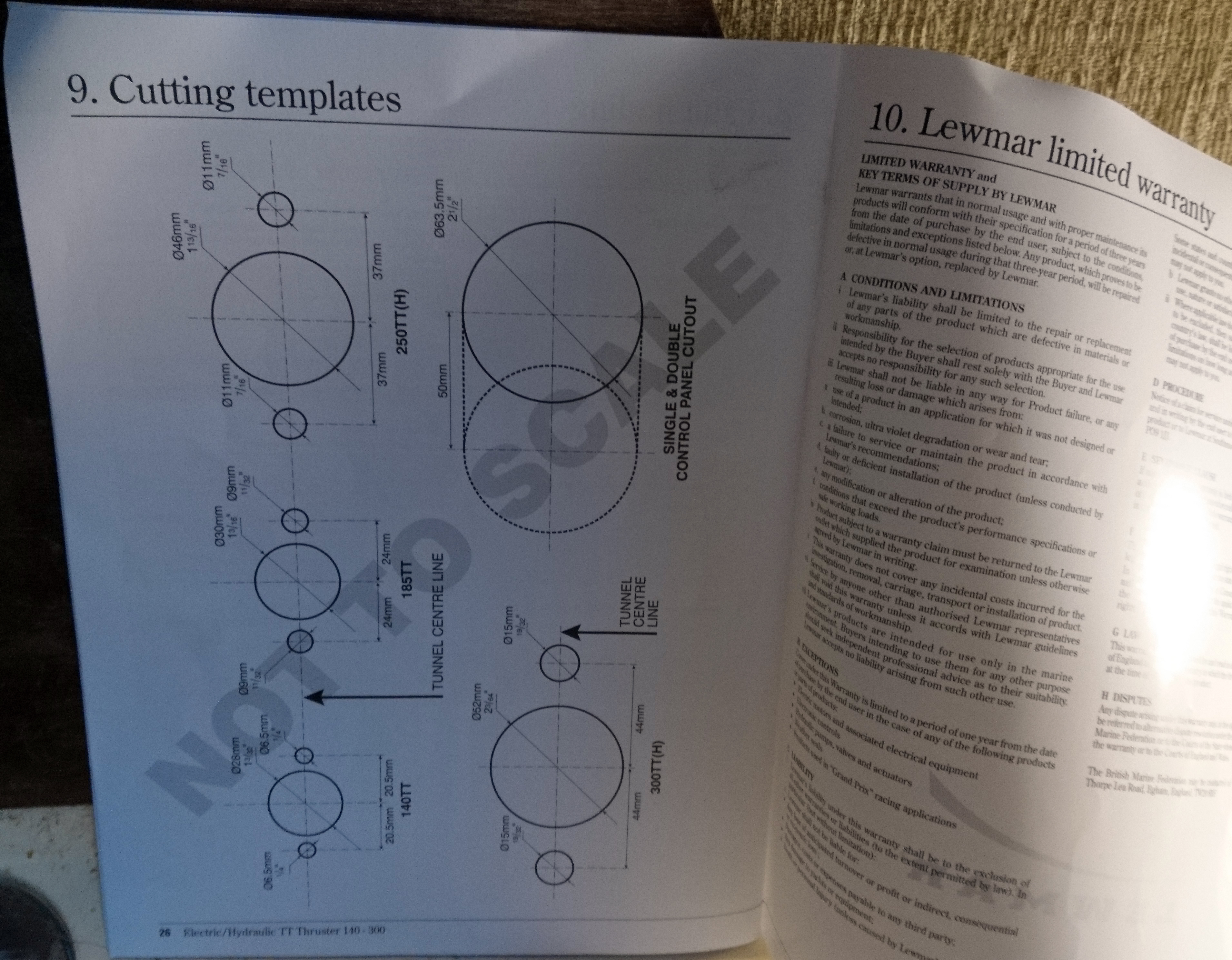
Honestly, whats the point of a Template page printed “not to scale”?
Template made (to 1:1 scale) for the battery shelf.
Shelf supports glassed in and everything coated with gel coat.
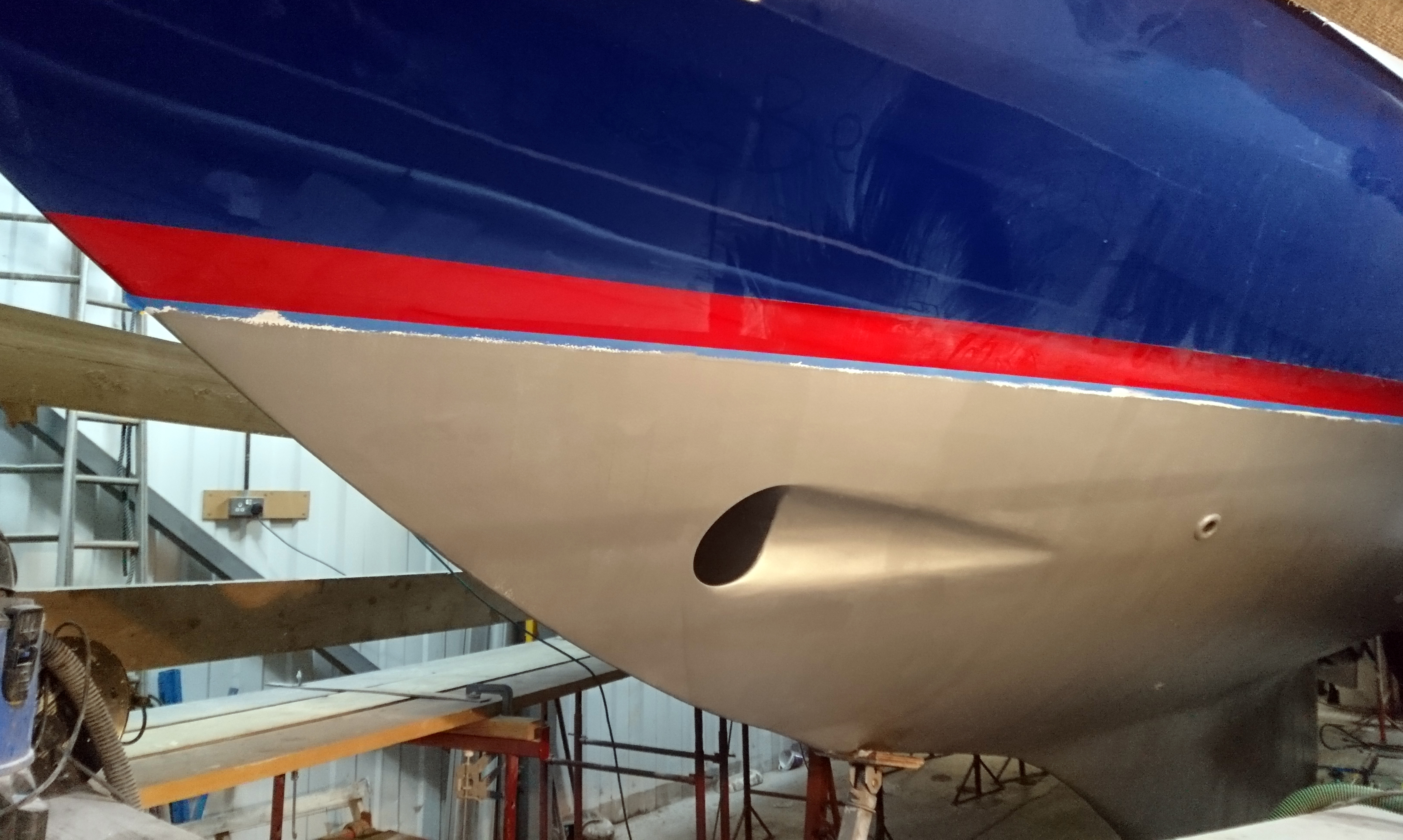
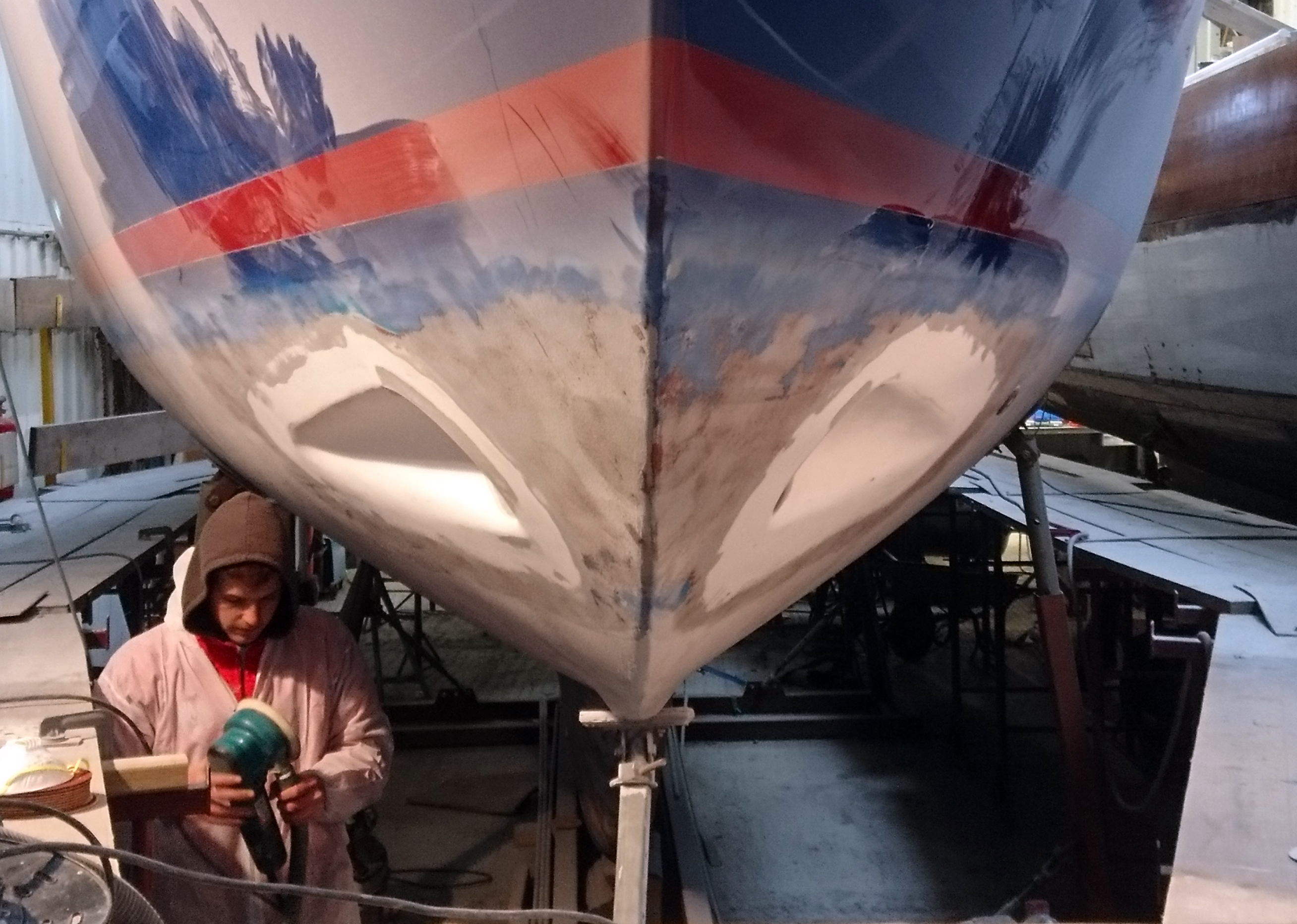
Outside the fairing complete and being primed.
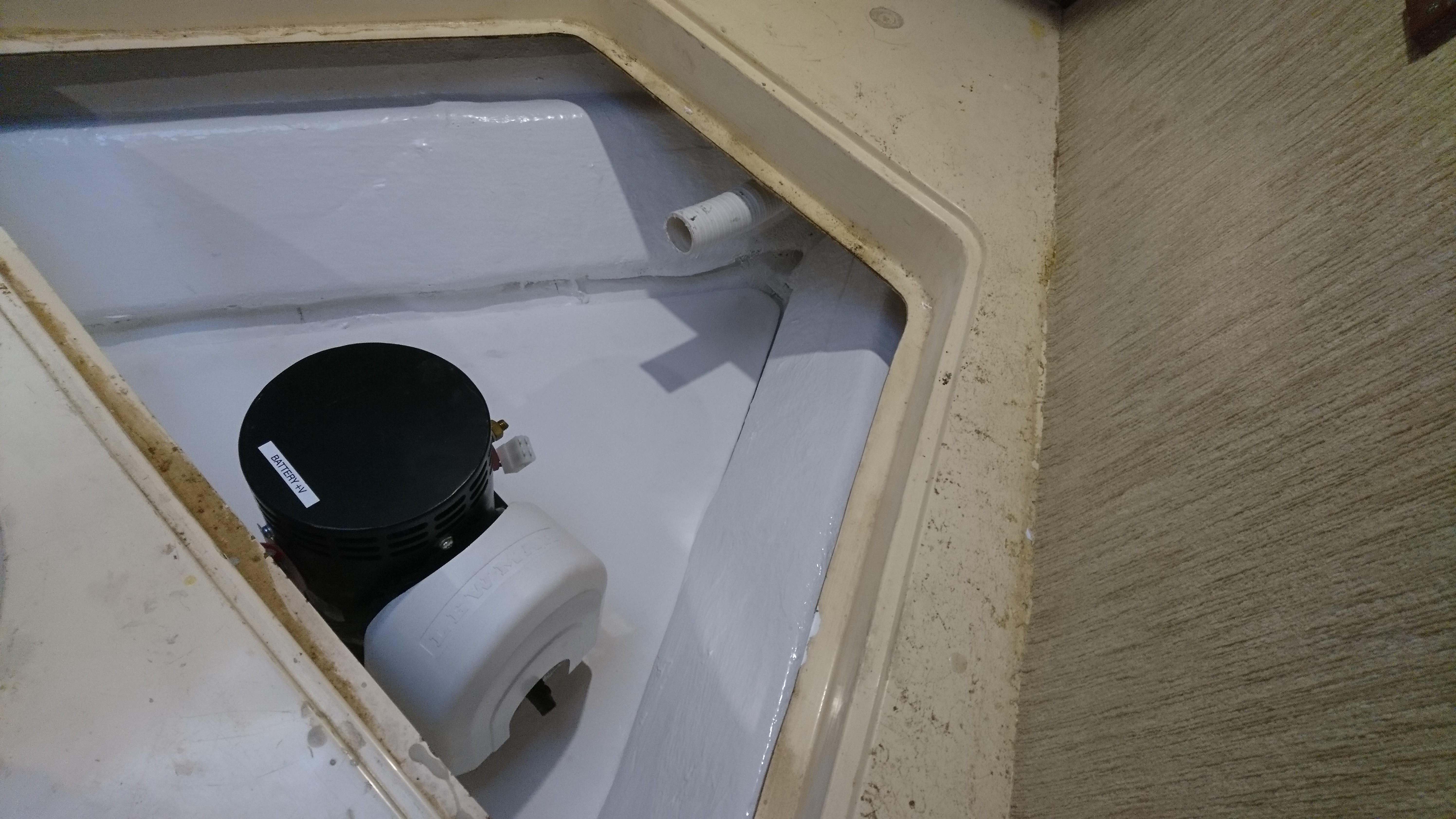
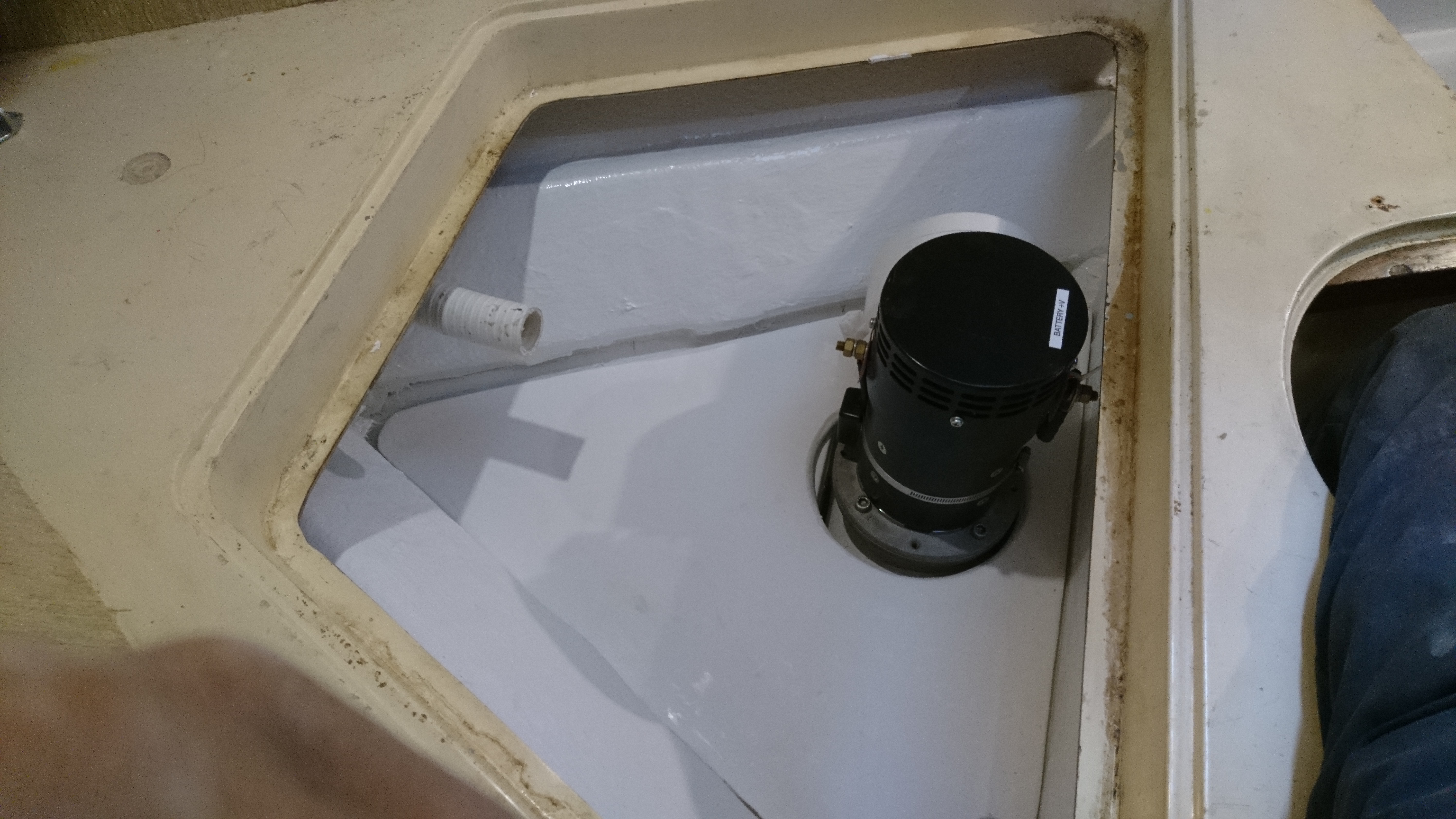
Motor and shelf fitted.
Internally the scallops are hardly noticeable.