Monthly Archives: March 2017

//March

Holding tank

Based at Southwold on the East Coast we generally have two choices when we leave the harbour.
Turn right or head straight across. (us locals try and avoid turning left!)
Heading straight across means that in 12 to 14 hours we’ll be in Dutch or Belgian waters and among the myriad of required items we should have on board or fitted is a holding tank, especially if we want to visit the inland waterways.
The trouble is many of our boats produced in the 80’s and 90’s really didn’t take this into account so it can be quite difficult to work out where to put an additional 100+ litre tank.
Most of the obvious places to fit a tank already have a tank so it means we have to get a bit creative.
Lucky for us Tek-Tanks  allows us to be creative and will build a tank to fit some really weird shapes.
I’m sure there are other tank builders that can do this as well but I’ll let you into a yard secret.  We go with what we know works for us. It’s always a risk going with another company as we rely so much on word of mouth that we cannot afford to fit something that fails, as it firstly reflects badly on us from the customers perspective, it will cost us money to fix which invariably will wipe out any margin we had built into the job and the delay will also affect the next jobs, with manpower, shed space availability etc
So when you find a system that works you stick with it.
Anyway an Oyster 406 came in for a new Beta engine, a new electric loo and a holding tank.
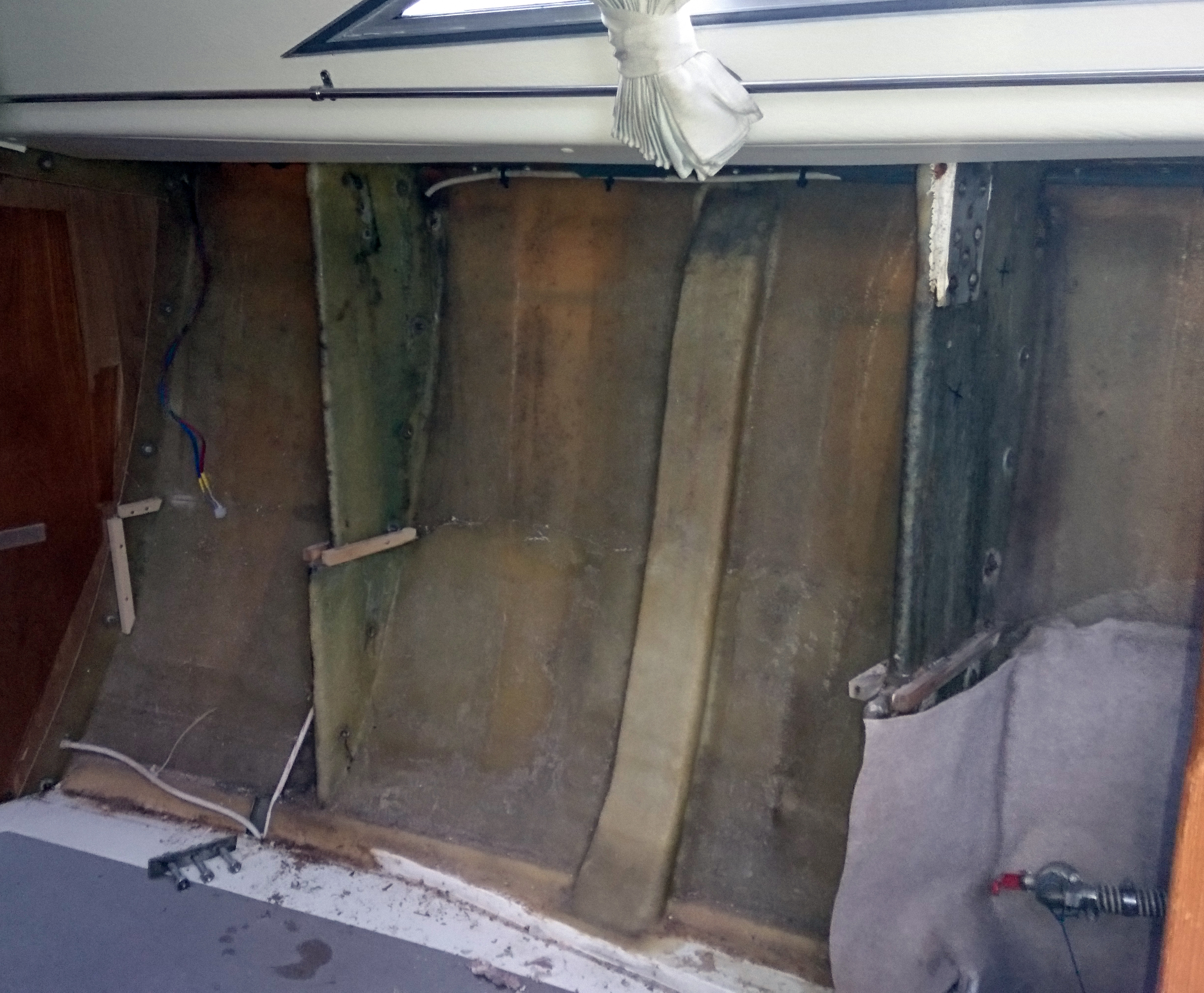
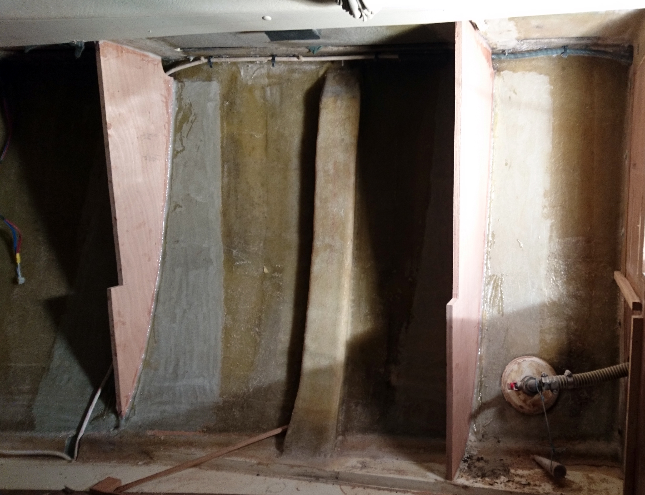
Whilst our engineering boys set about the “how do we get the old engine out?” issue, I got on with measuring the total cupboard space above and behind the fwd Heads and as long as the owners could find a new location for their tooth brushes and shampoo I believed I could get a 110 lt tank in there.
Yes it was a strange shape but nothing out of the ordinary for Tek-Tanks who whilst not very cheap have come up trumps every time I’ve set them a challenge.
It would require a little bit of surgery to the boat interior and also some thought to ensure there is future access.
Original builders/designers tend not to lose too much sleep over ensuring access to things that could need maintenance in the future, with quite large areas of boat that are simply inaccessible.
Being sailors and owners ourselves coupled with the frustration of getting to fittings, bolts, pipes, cables, not to mention areas of hull that you need to get access to in case some numpty t-bones you in a marina, we like to enable that whatever we put in, can be removed and attempt to provide access  to previously no go areas.
We could have totally filled up the available space and found another 30 litres of tank space but access would have been made much harder to the top fittings such as the air filter/breather, flush out and level sender, so practicality won the day.
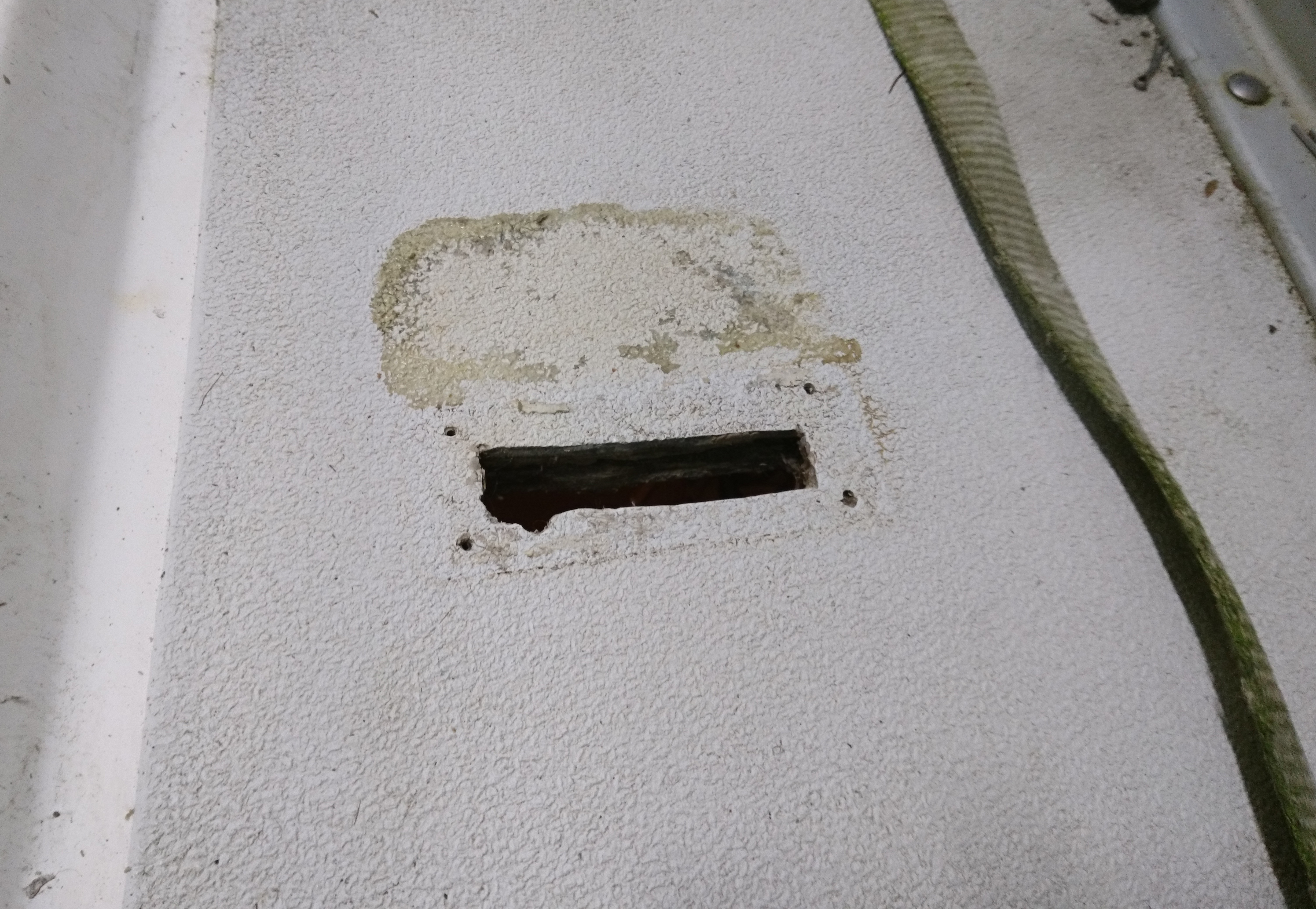
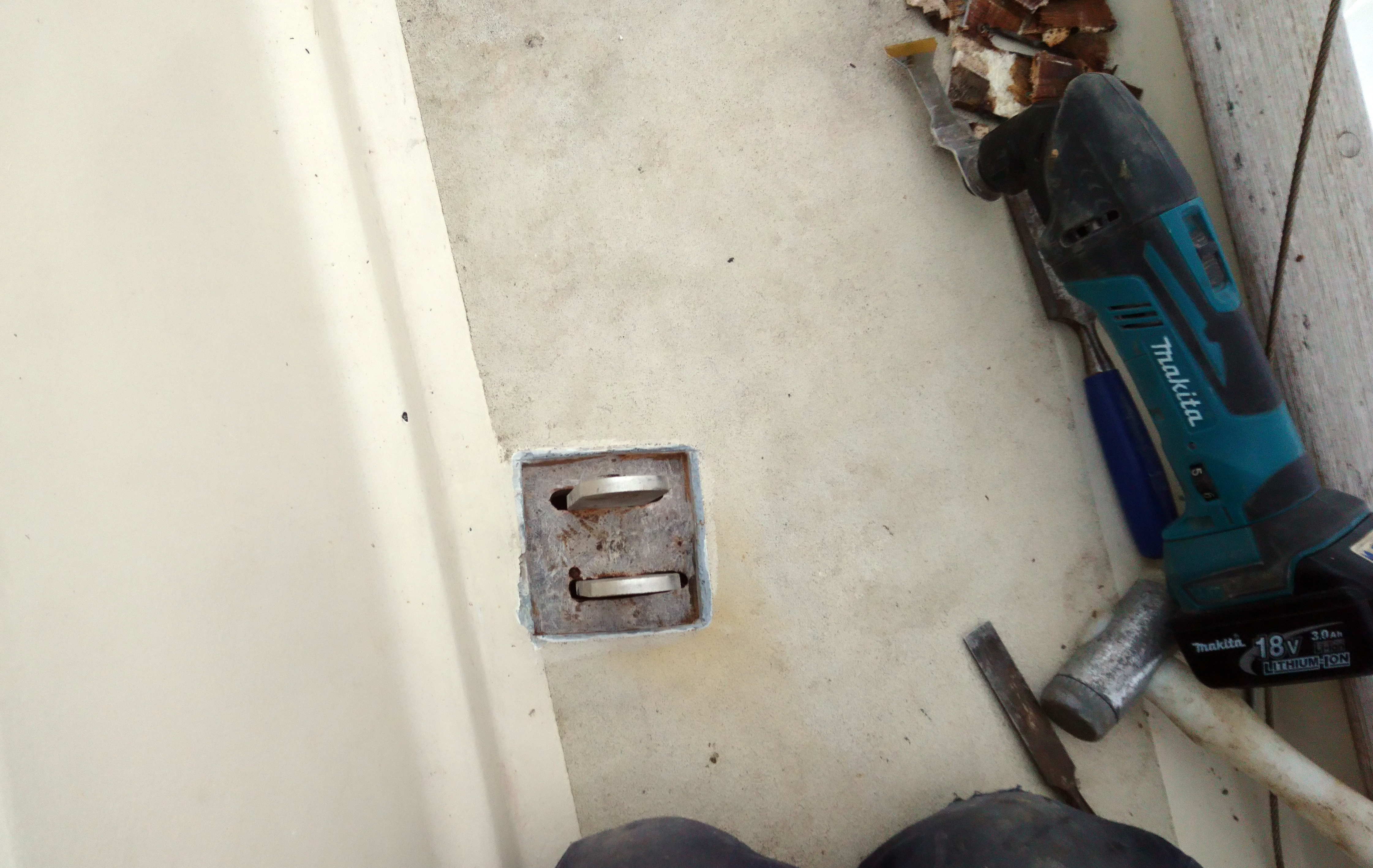
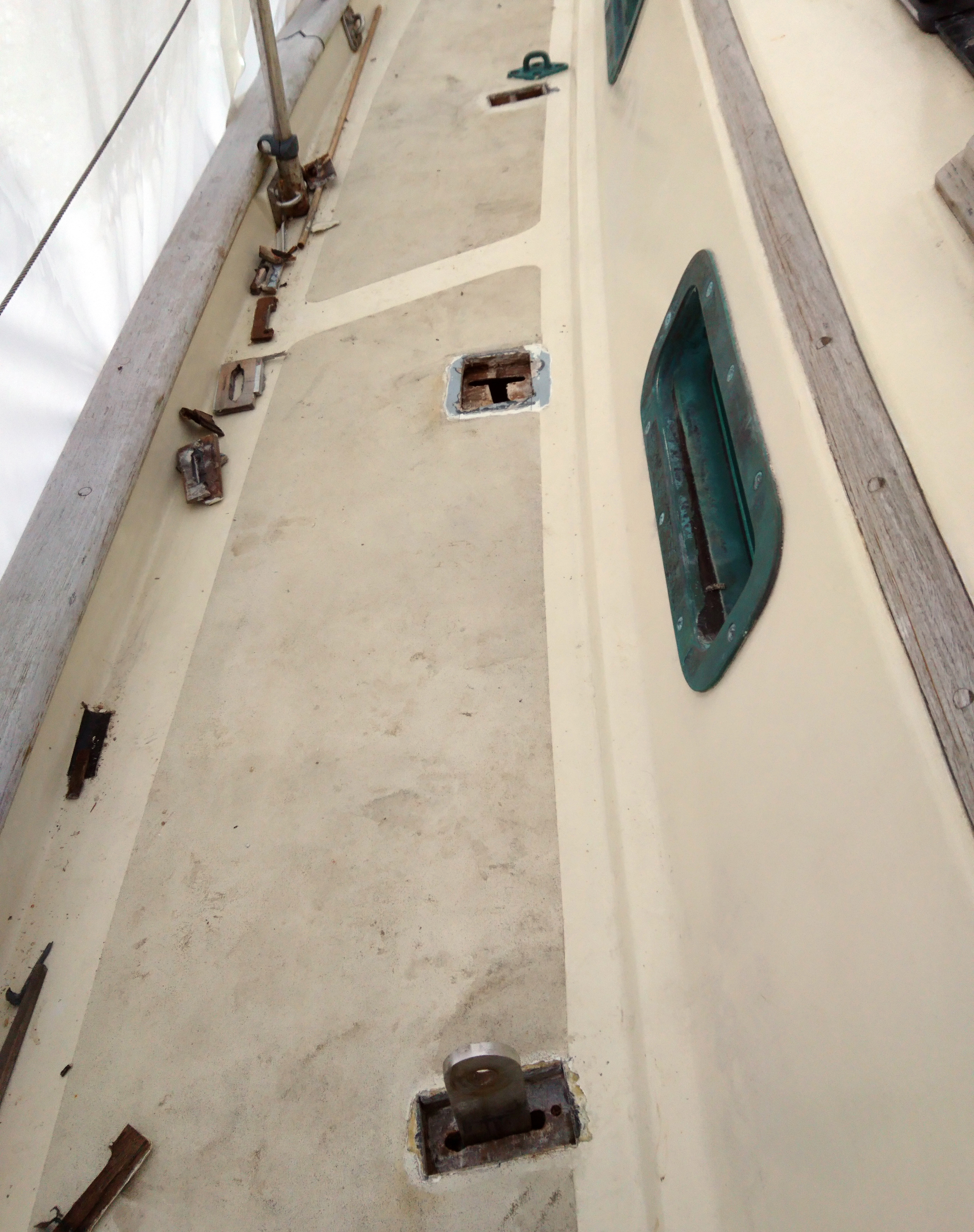
The heads molding is quite tight to the hull so the skin fittings are forward of the main bulkhead in the forward cabin.
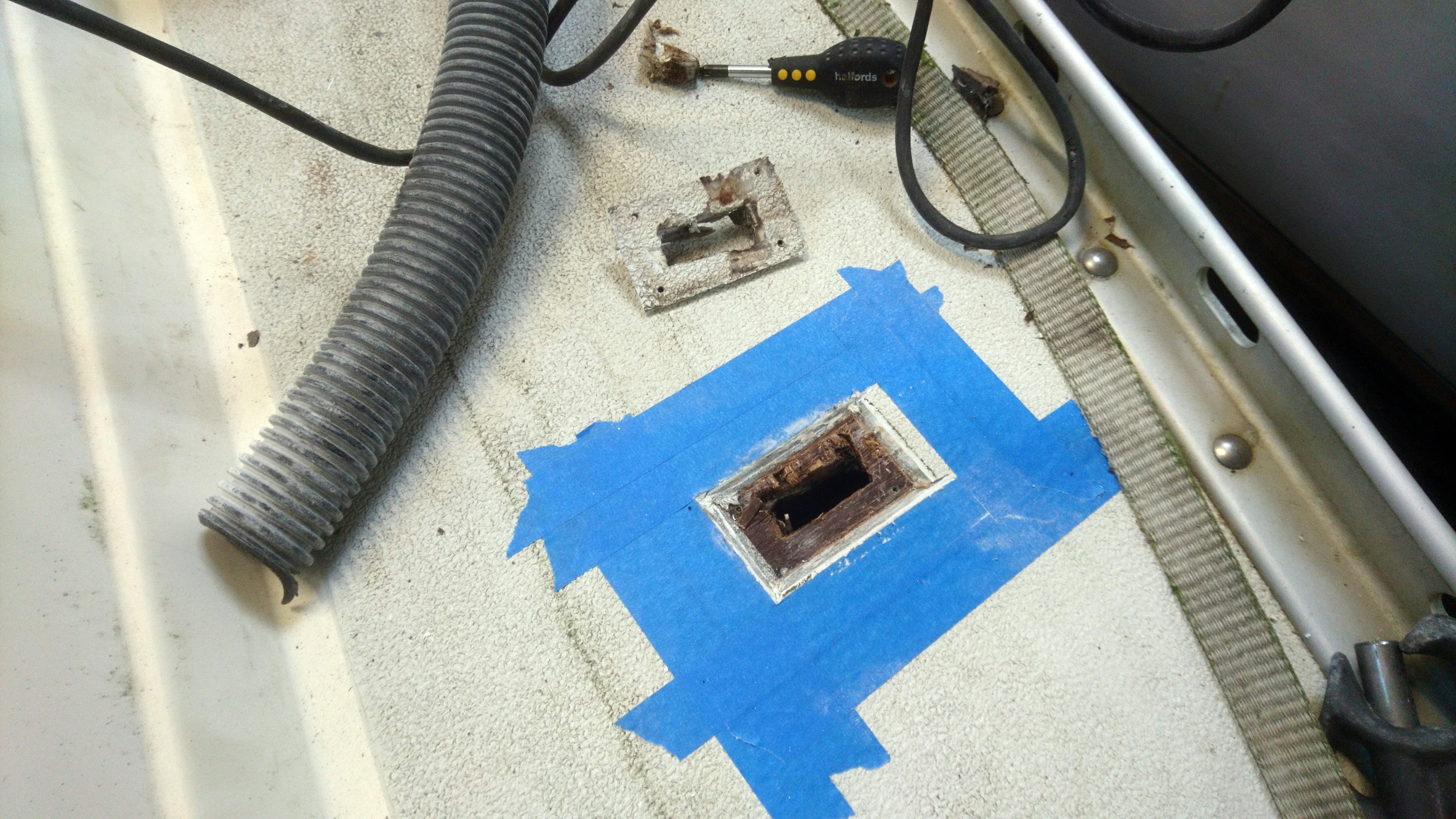
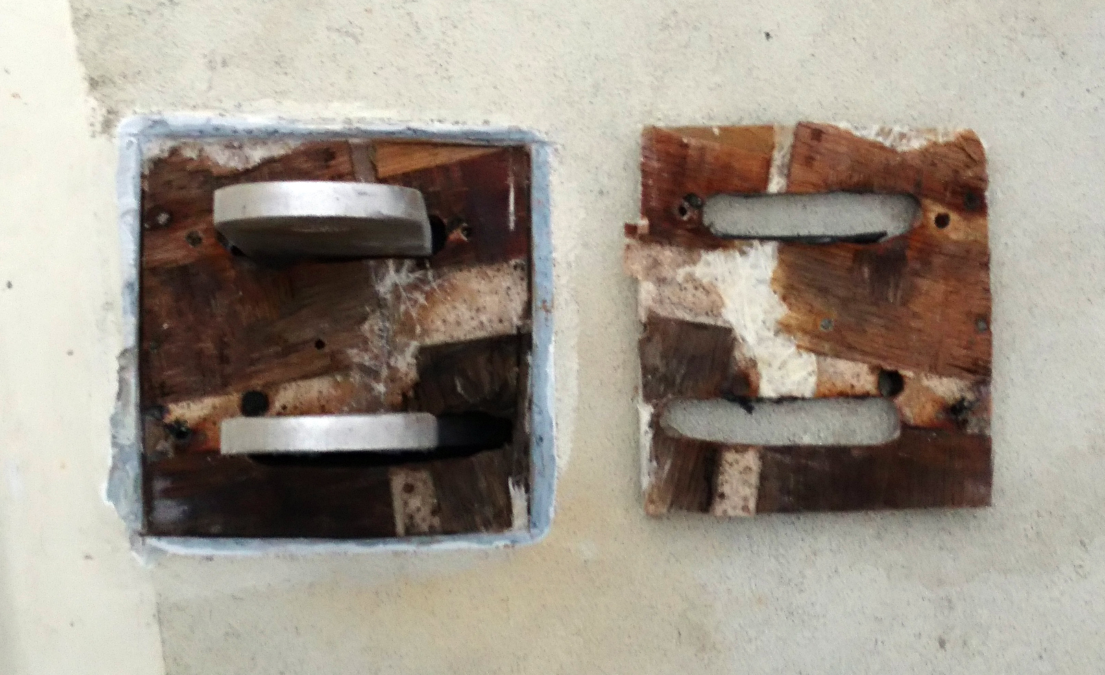
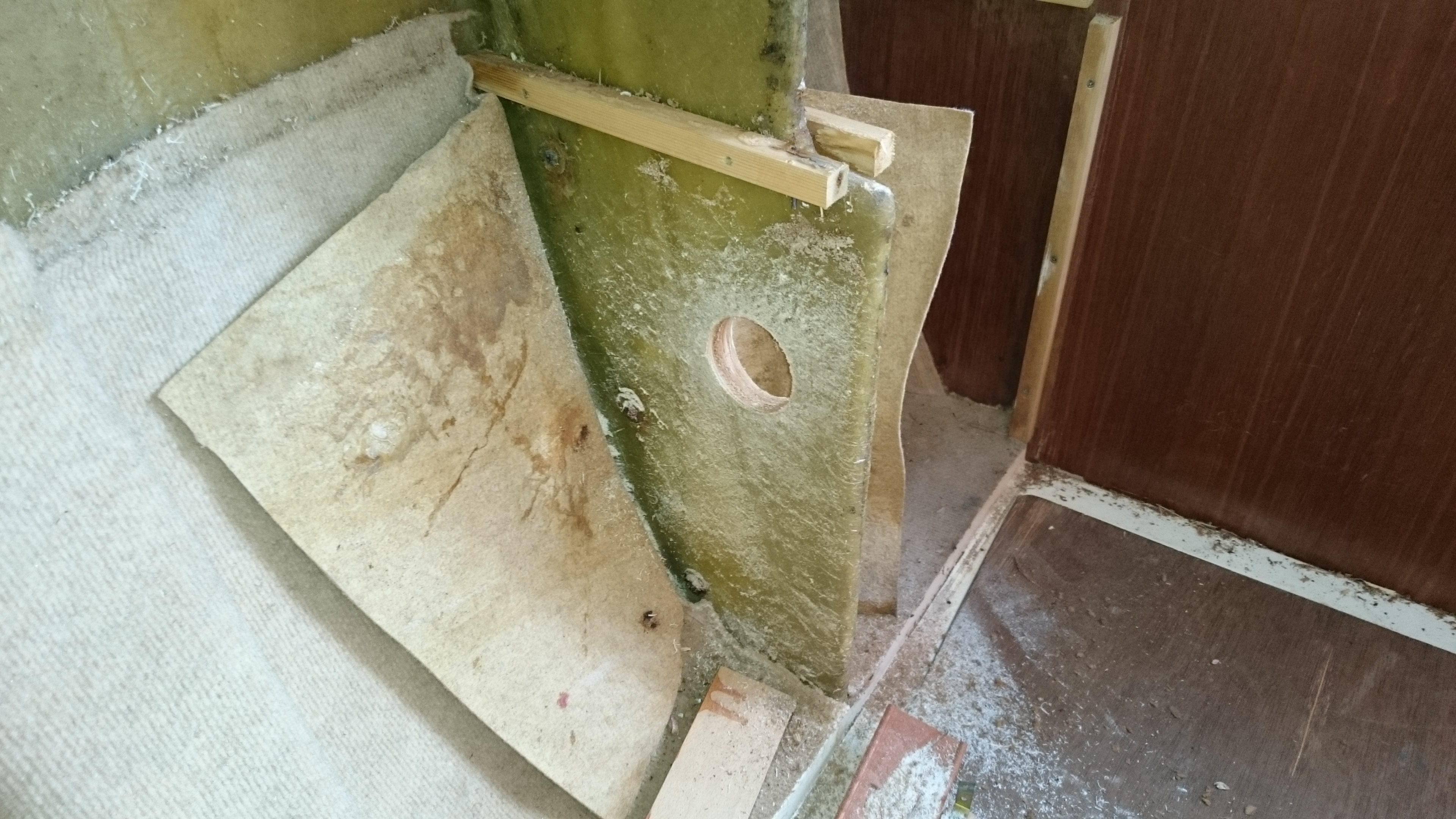
Changing fittings including toilets will always result in redundant and unsightly holes so this dictated the location of the access hatch and this in turn finalised the position of the diverter valve.
The electric loo switches were mounted through 5mm white plastic sheet glued to the side of the sink cabinet, again covering a number of redundant holes.
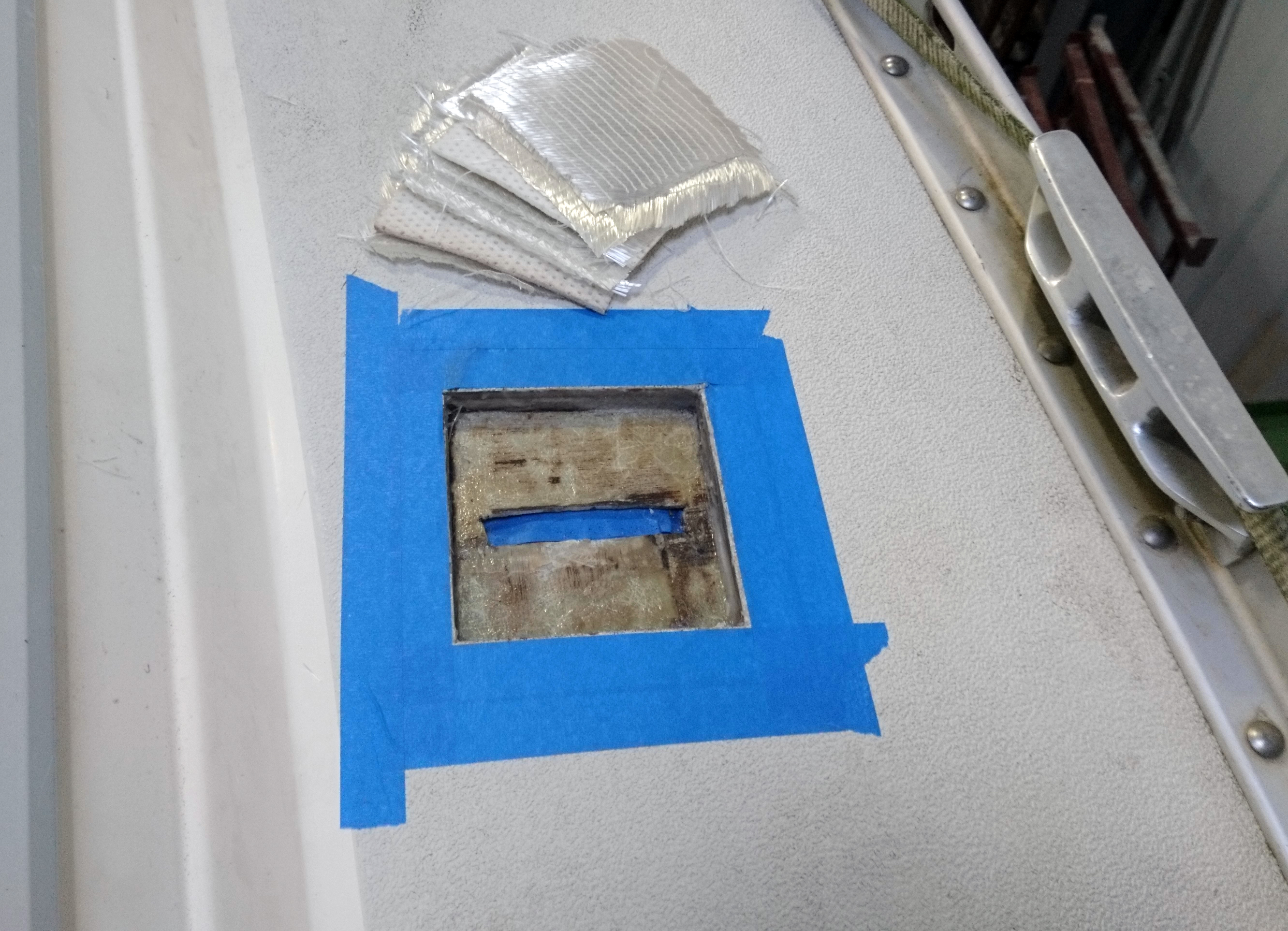
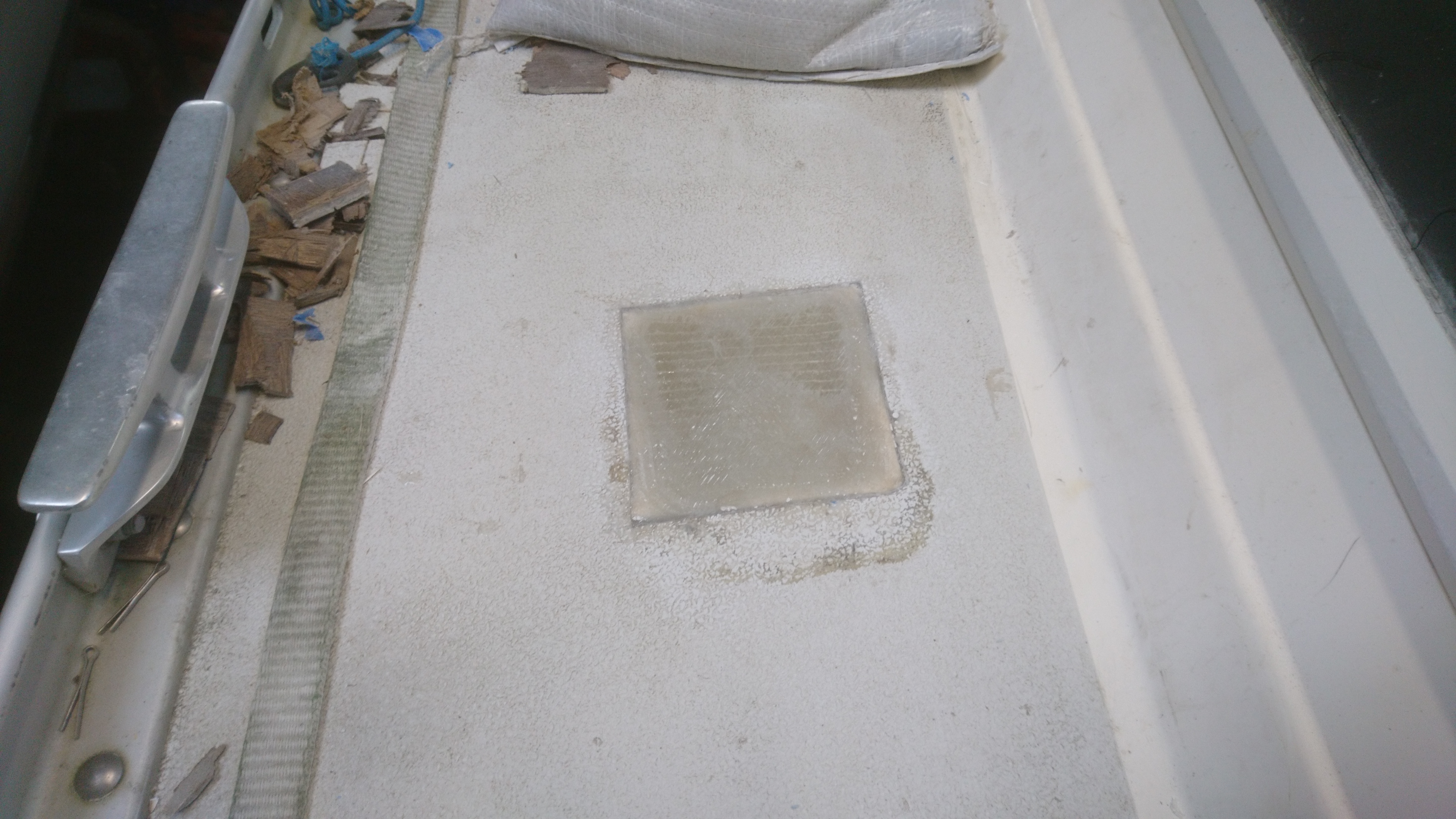
We could have glassed and re gelcoated but the extra expense was viewed as being unnecessary.
The one issue I have with electric loos are they are so incredibly noisy and Jabsco even has the temerity to call it the quiet flush.
There should be a little flag raised when you use it in a marina saying “Yes we have a holding tank”.
That said it works well and based on the lack of complaints from customers they seem very reliable.
This is the first time I’ve used the Jabsco diverter valve and I’m hoping it proves reliable as fitting it was a breeze especially as the outlets are movable and allow many angles for the 38mm pipework.

On testing the loo and inlet pumps were more than adequate to discharge into the tank and with the diverter valve set to empty the tank level dropped like a stone.
An initial worry was about having 100kg of extra weight up high and out on one side but once the boat was on the water it made very little  difference visually and of course, once offshore the tank could be emptied anyway.
The owners report back was very positive and apparently the noisy loo issue is not as bad as I feared as it takes such a short time to flush.

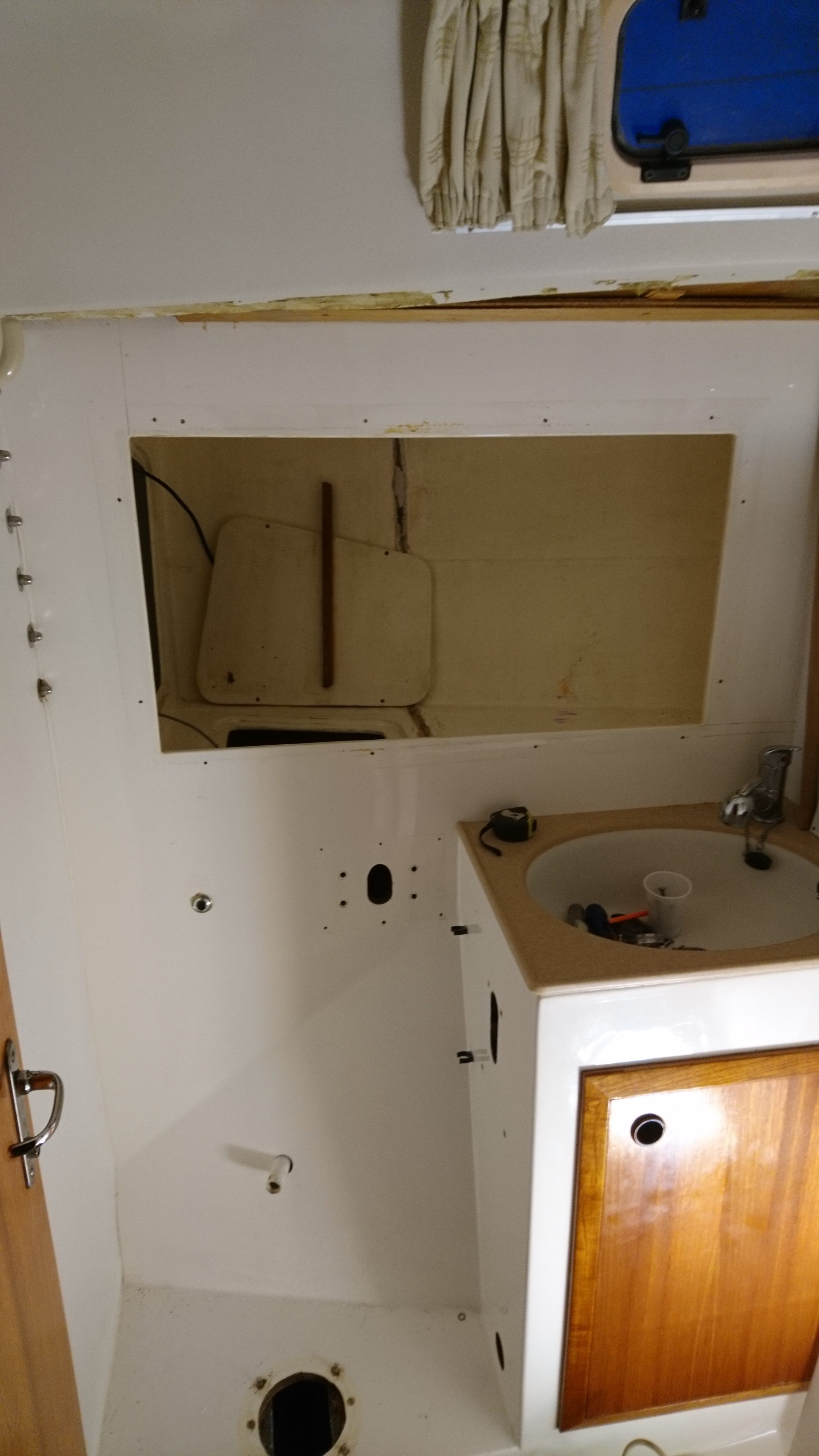
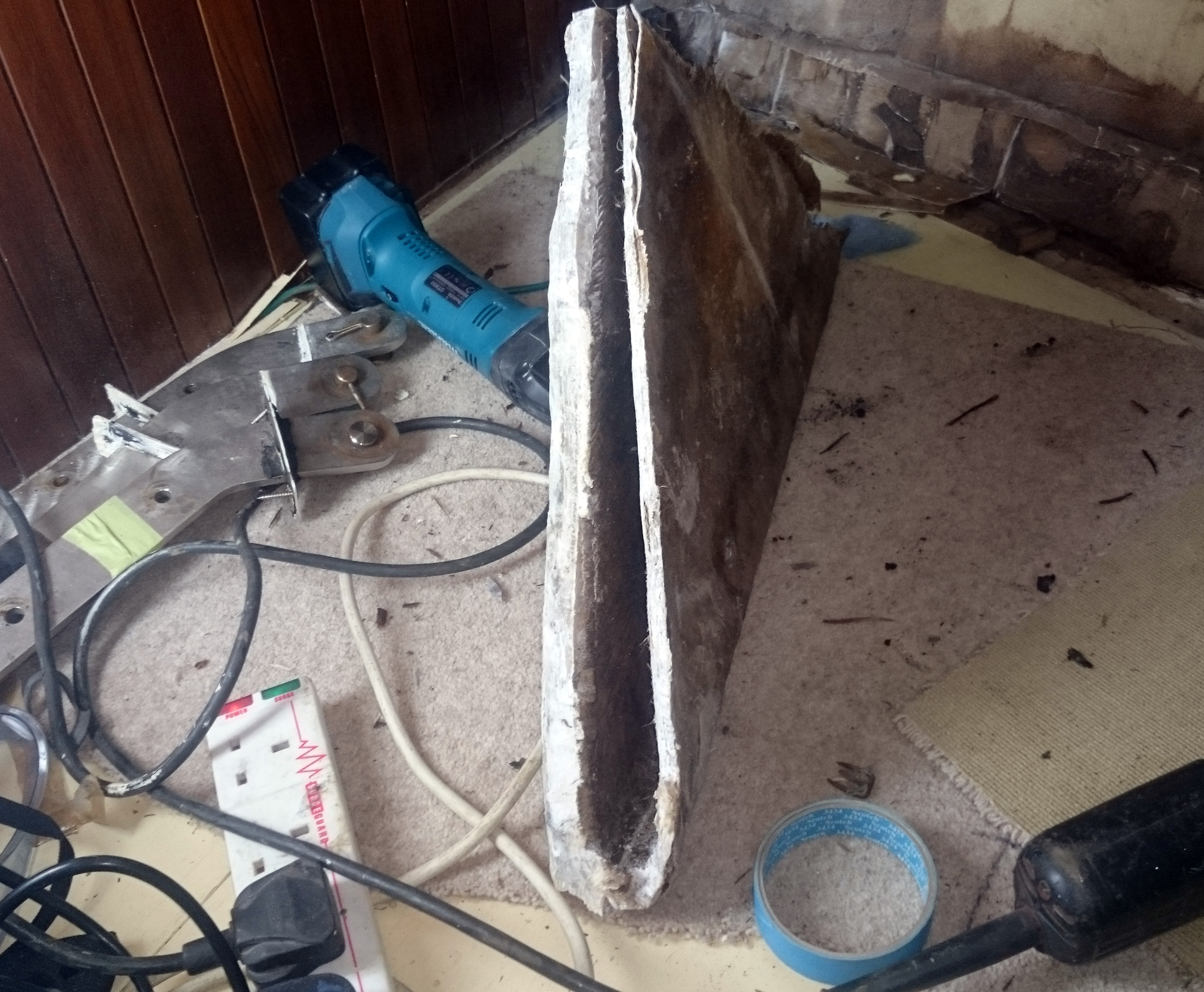
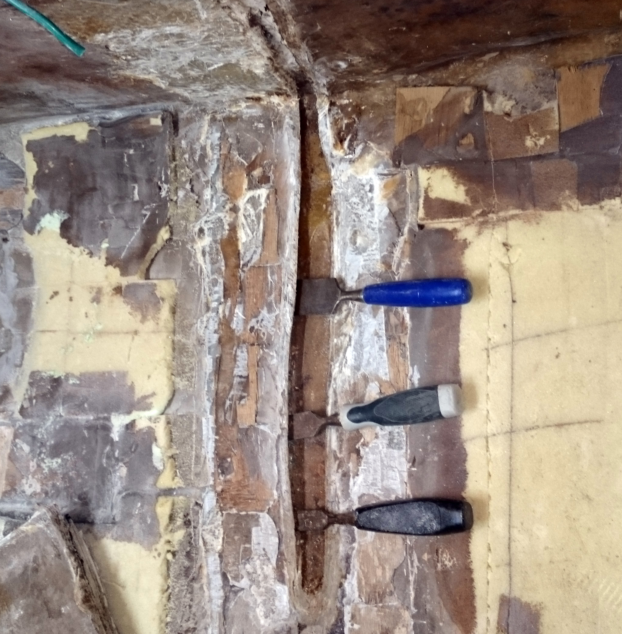
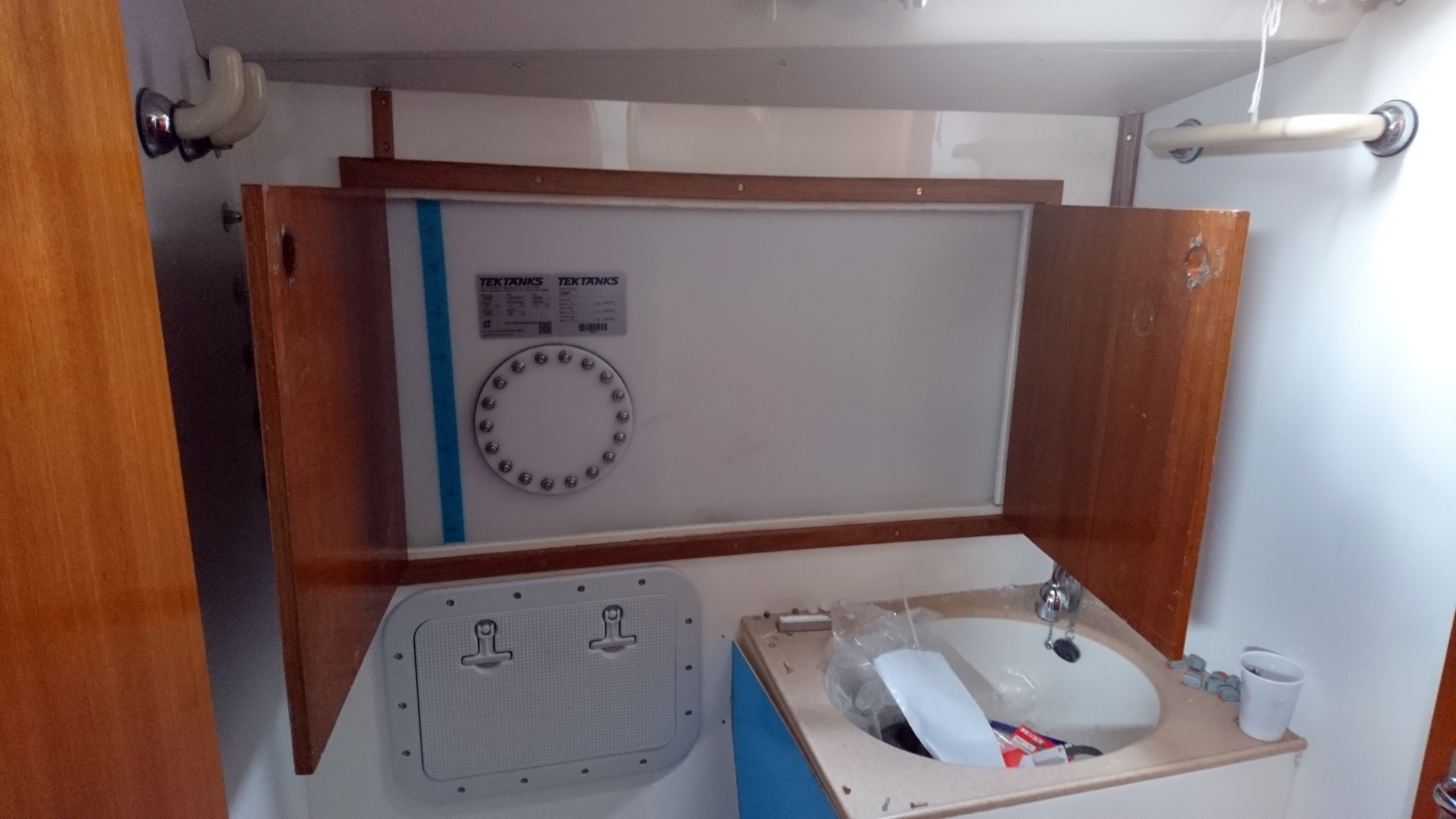
With the locker doors, a shelf and a dividing panel removed we found we could squeez a 100 liter tank inside.

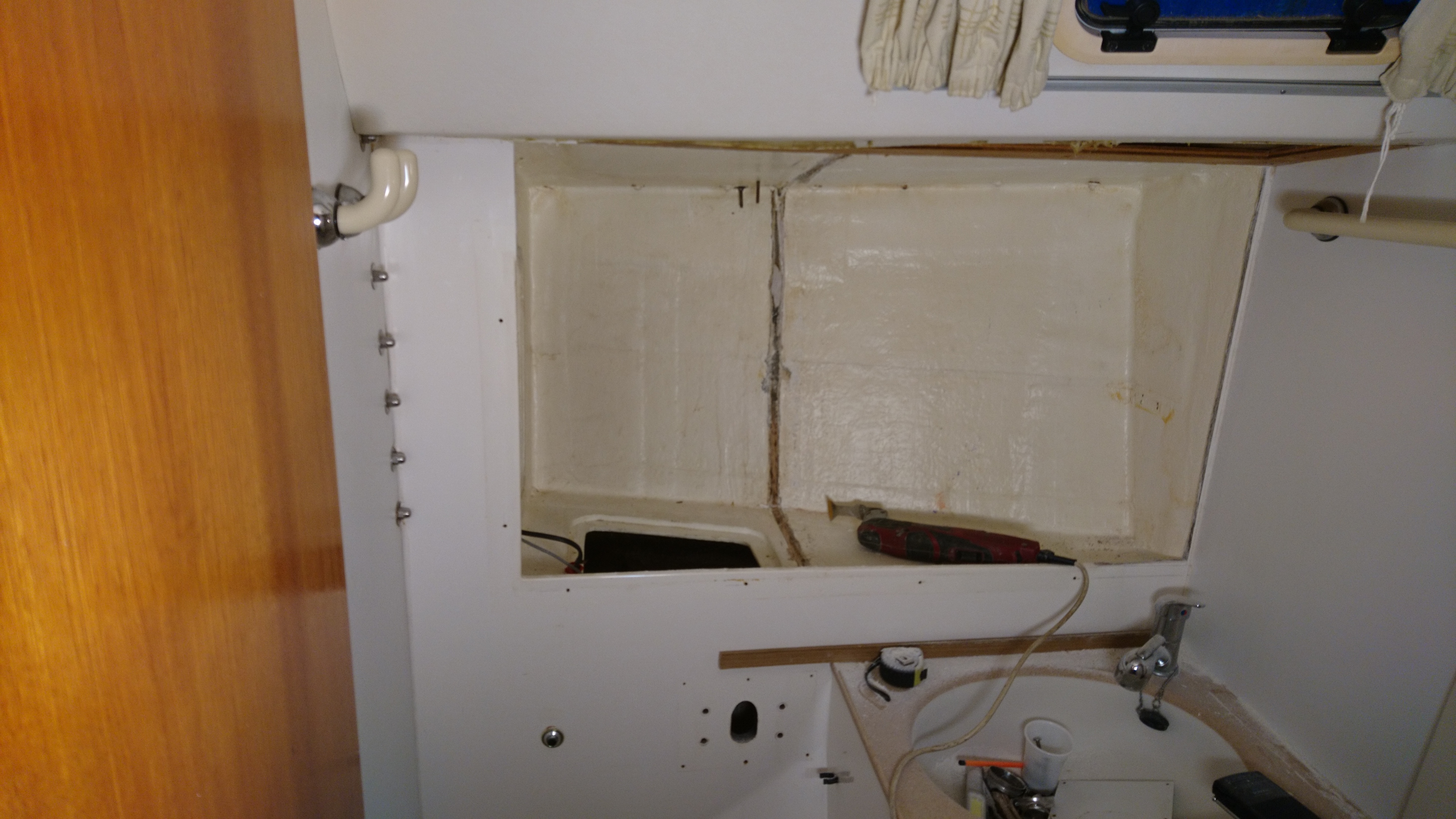
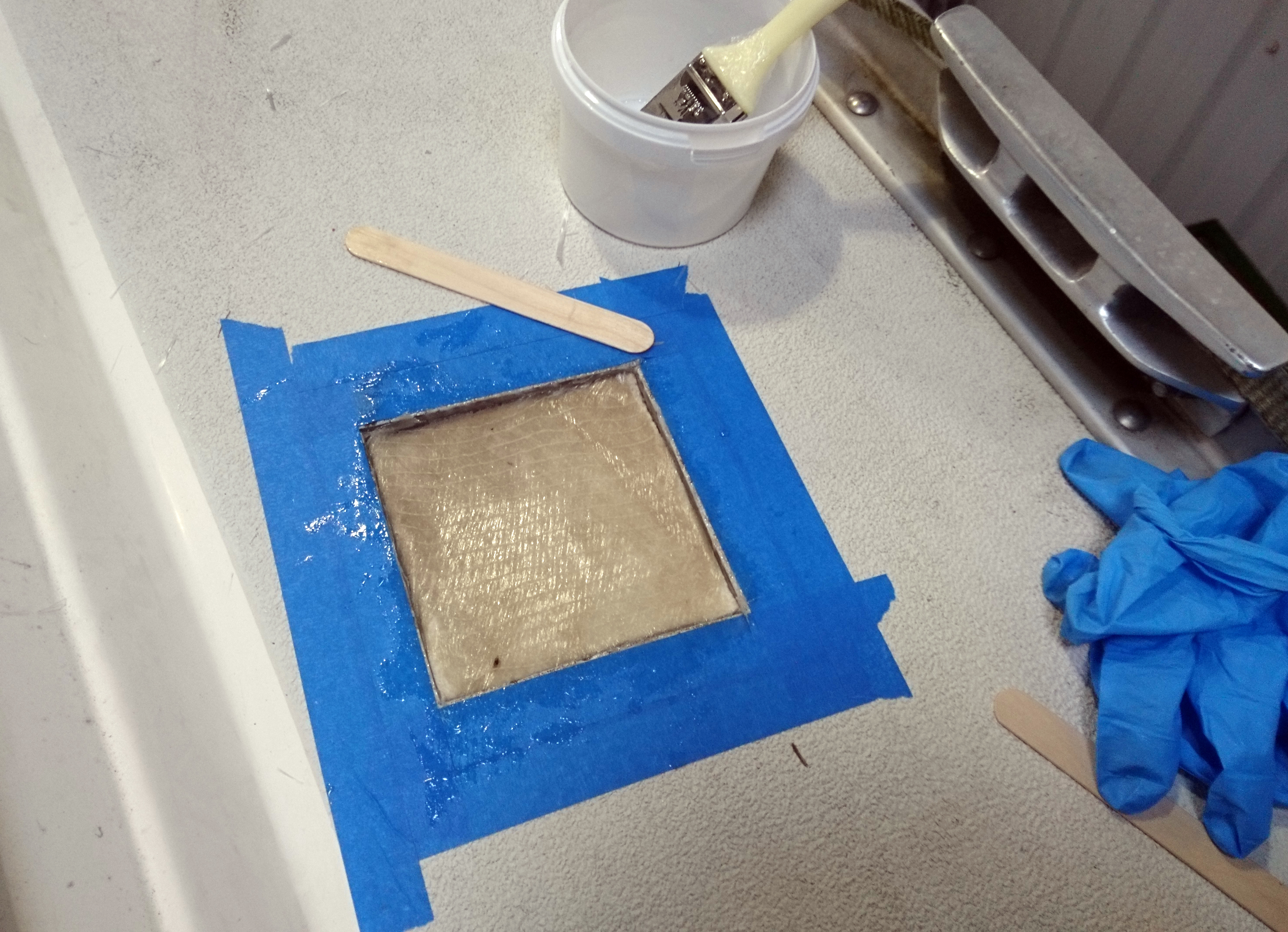
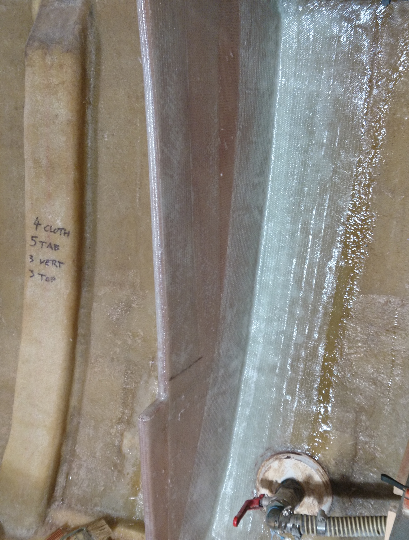
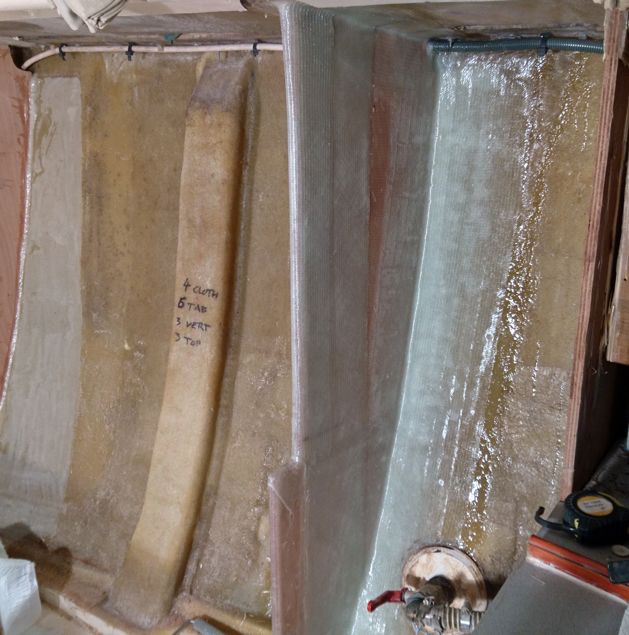
However to get it in we would have to cut away some of the fibreglass above and to one side of the locker.

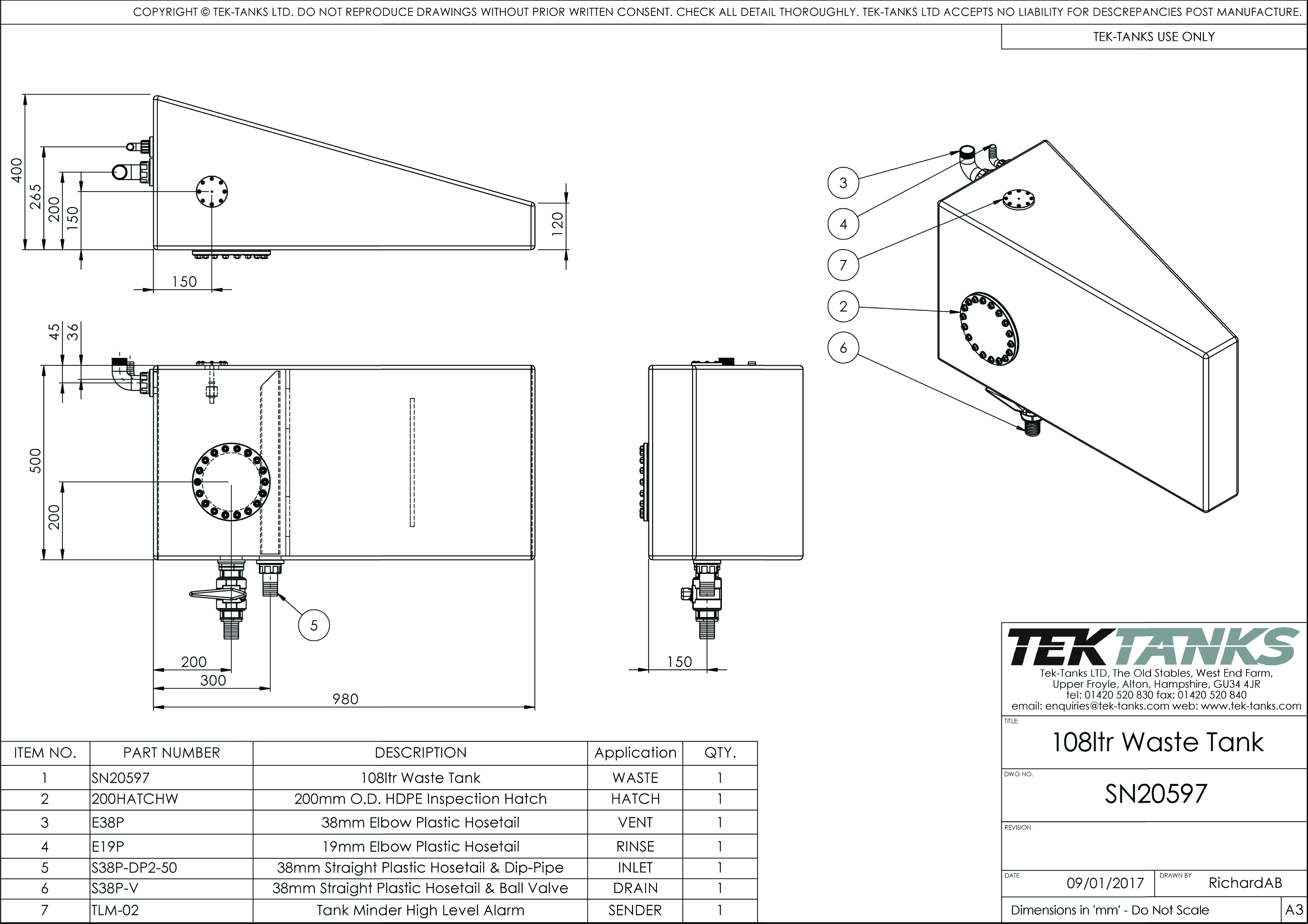
I sent Tek Tanks a rough drawing and they send me a proper one back for approval before manufacture.

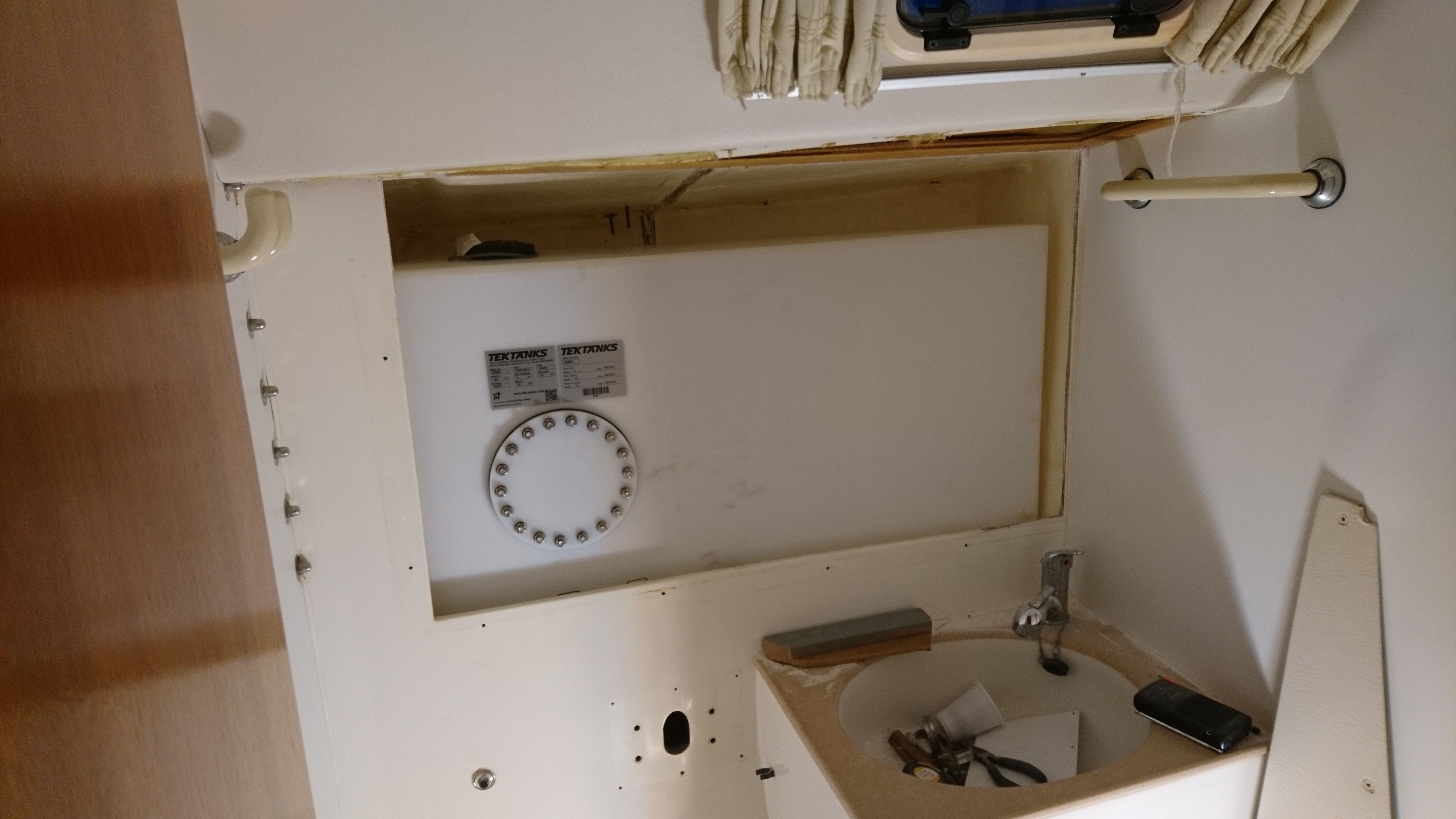
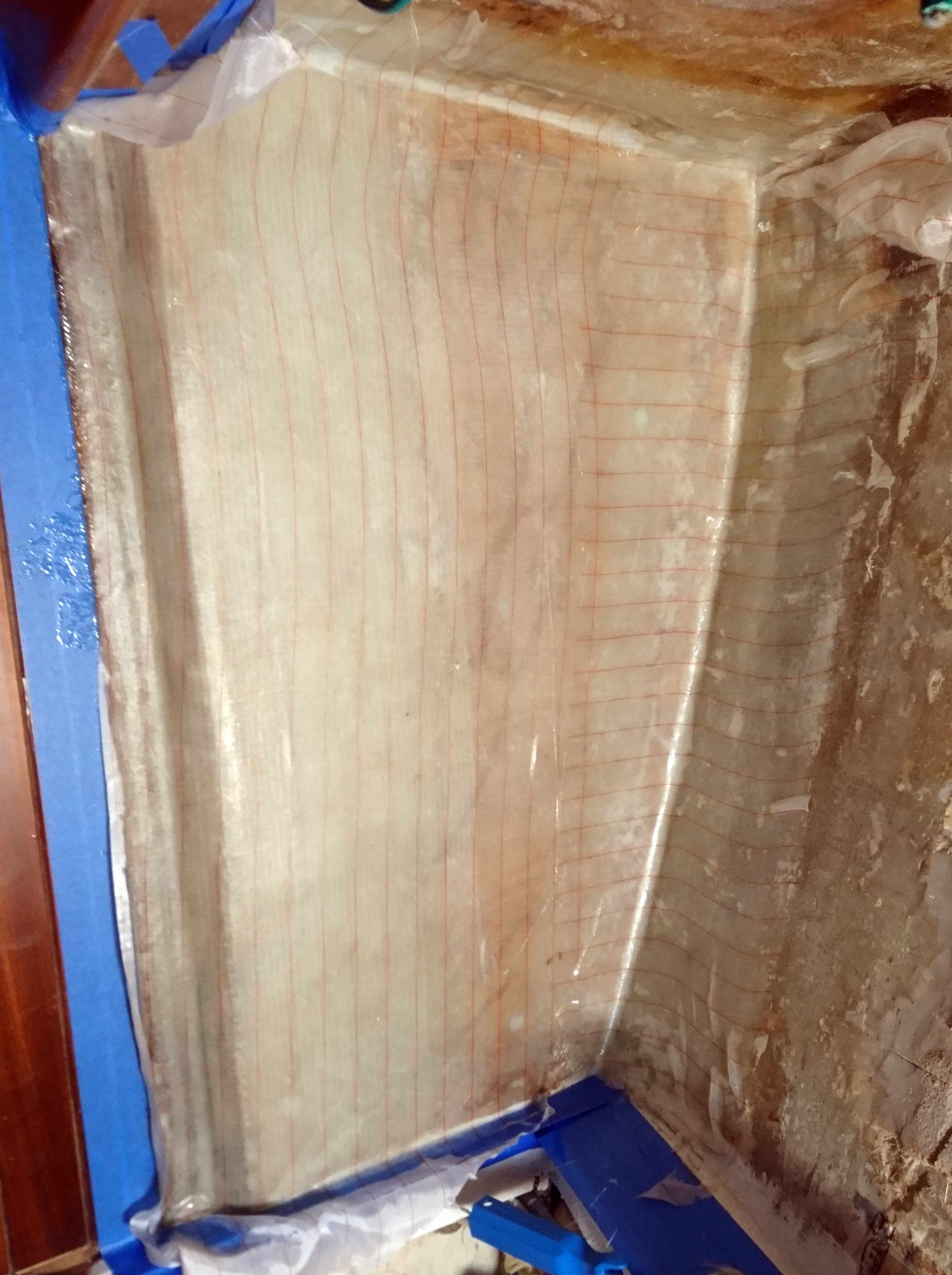
A couple of weeks later we had a tank ready for a test fit, time to test whether I can measure odd shapes correctly.
Thankfully I did.

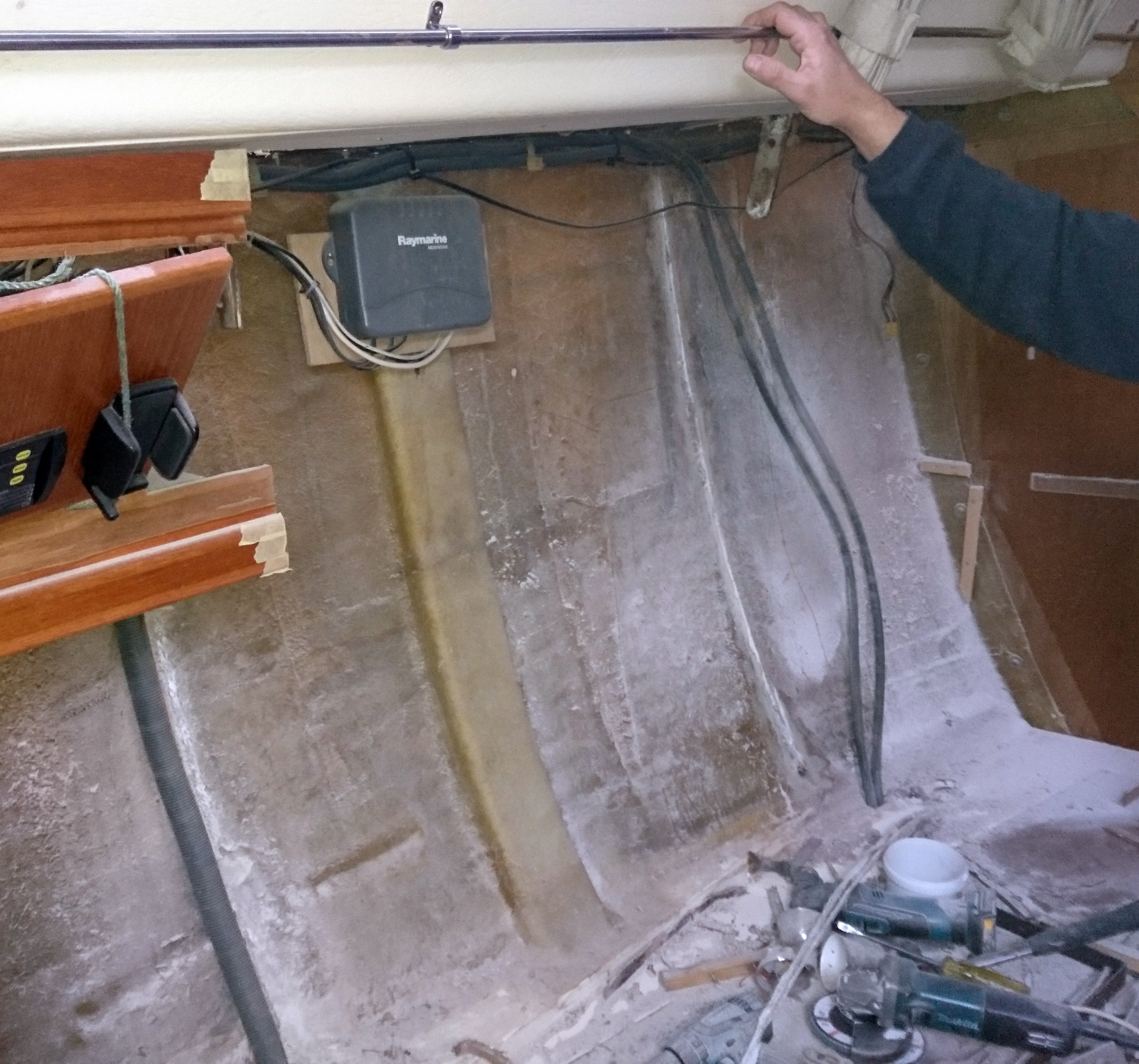
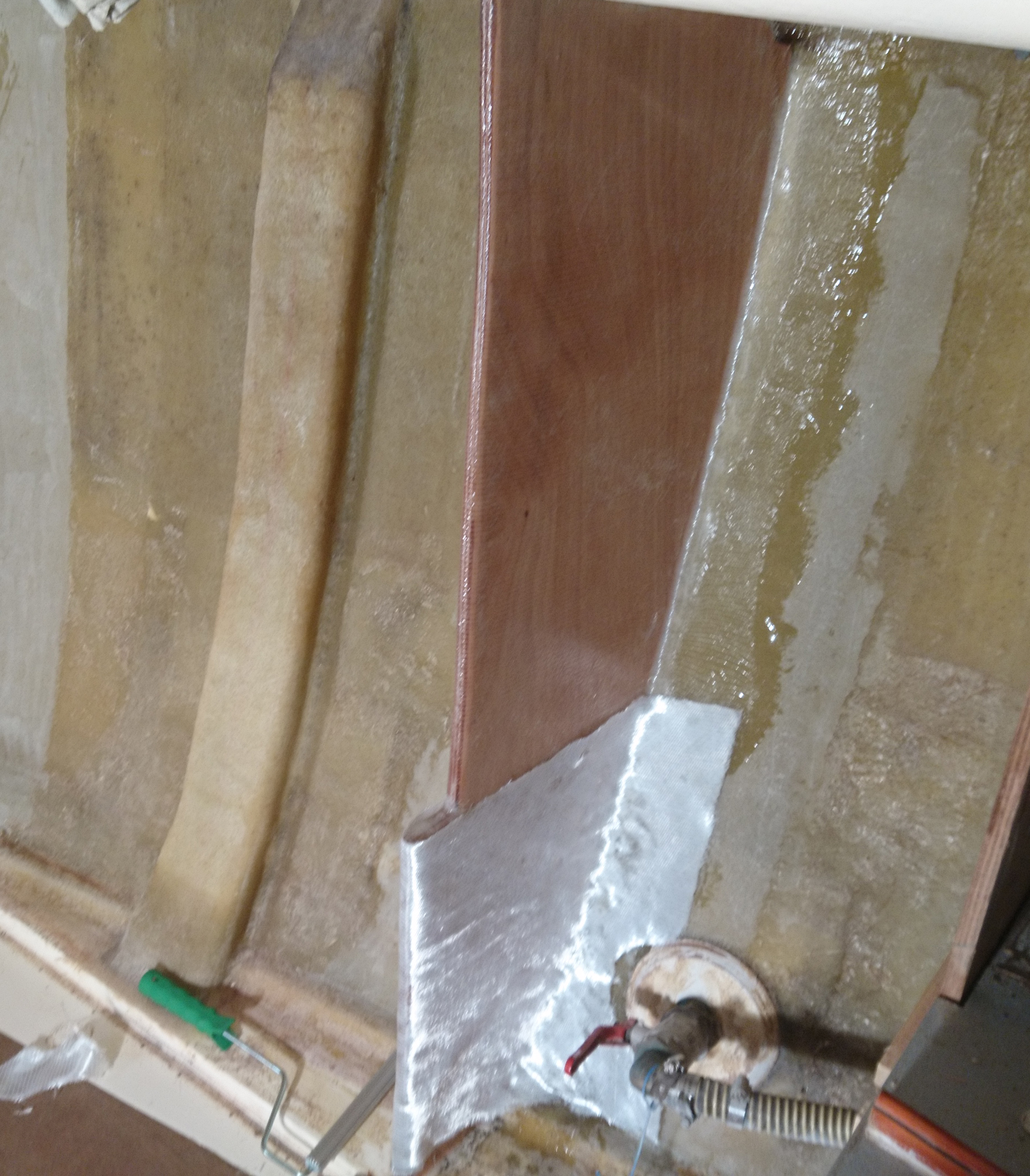
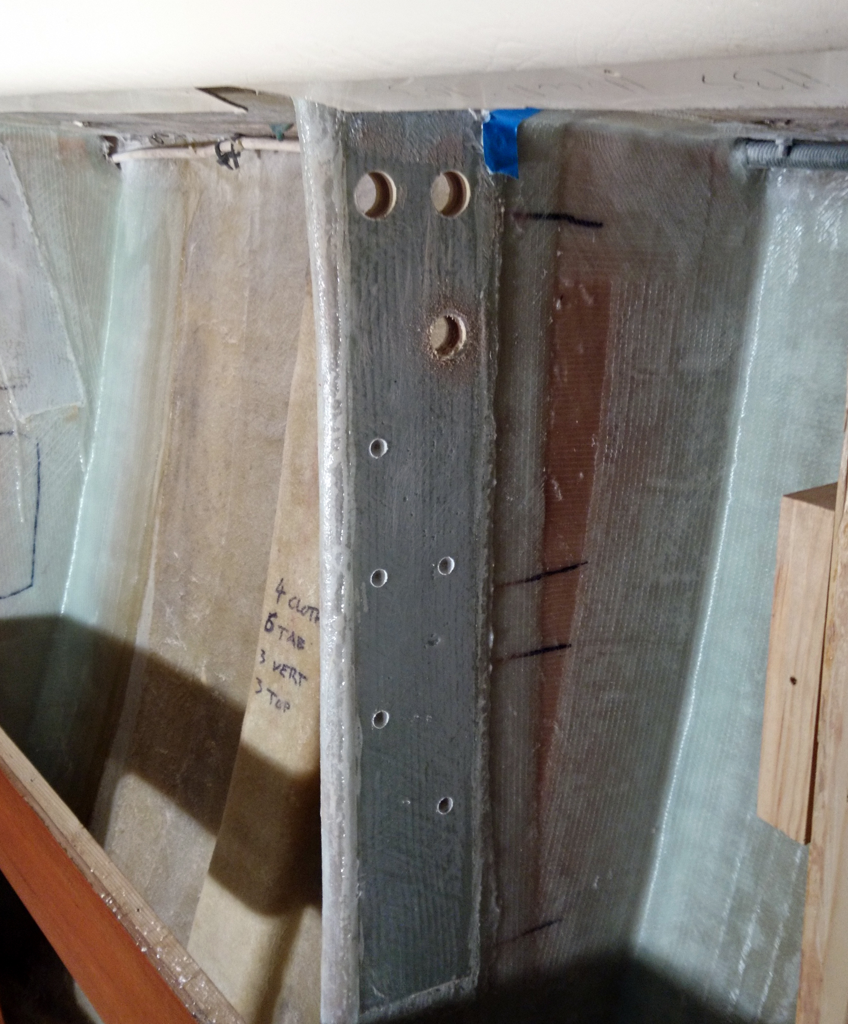
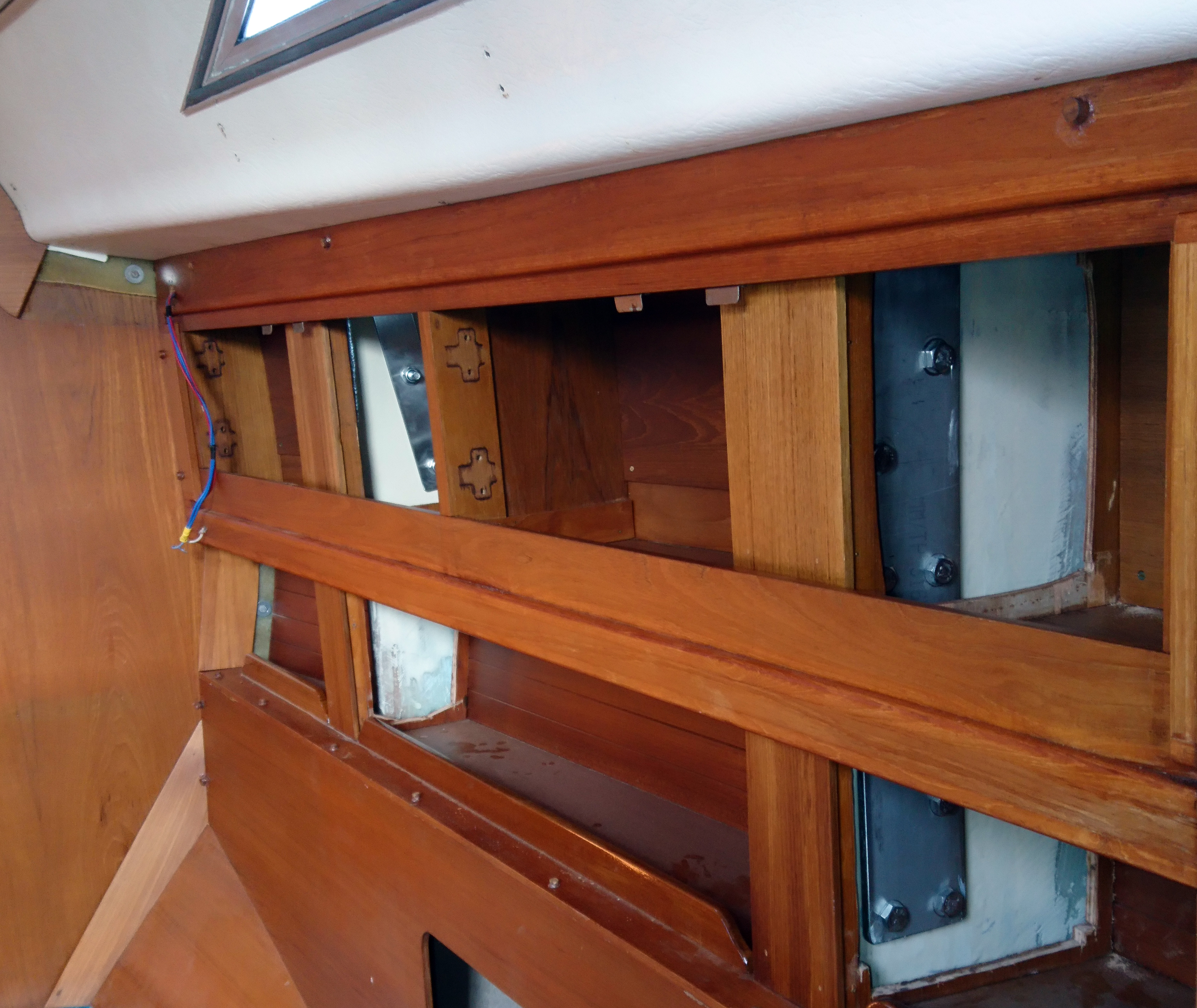
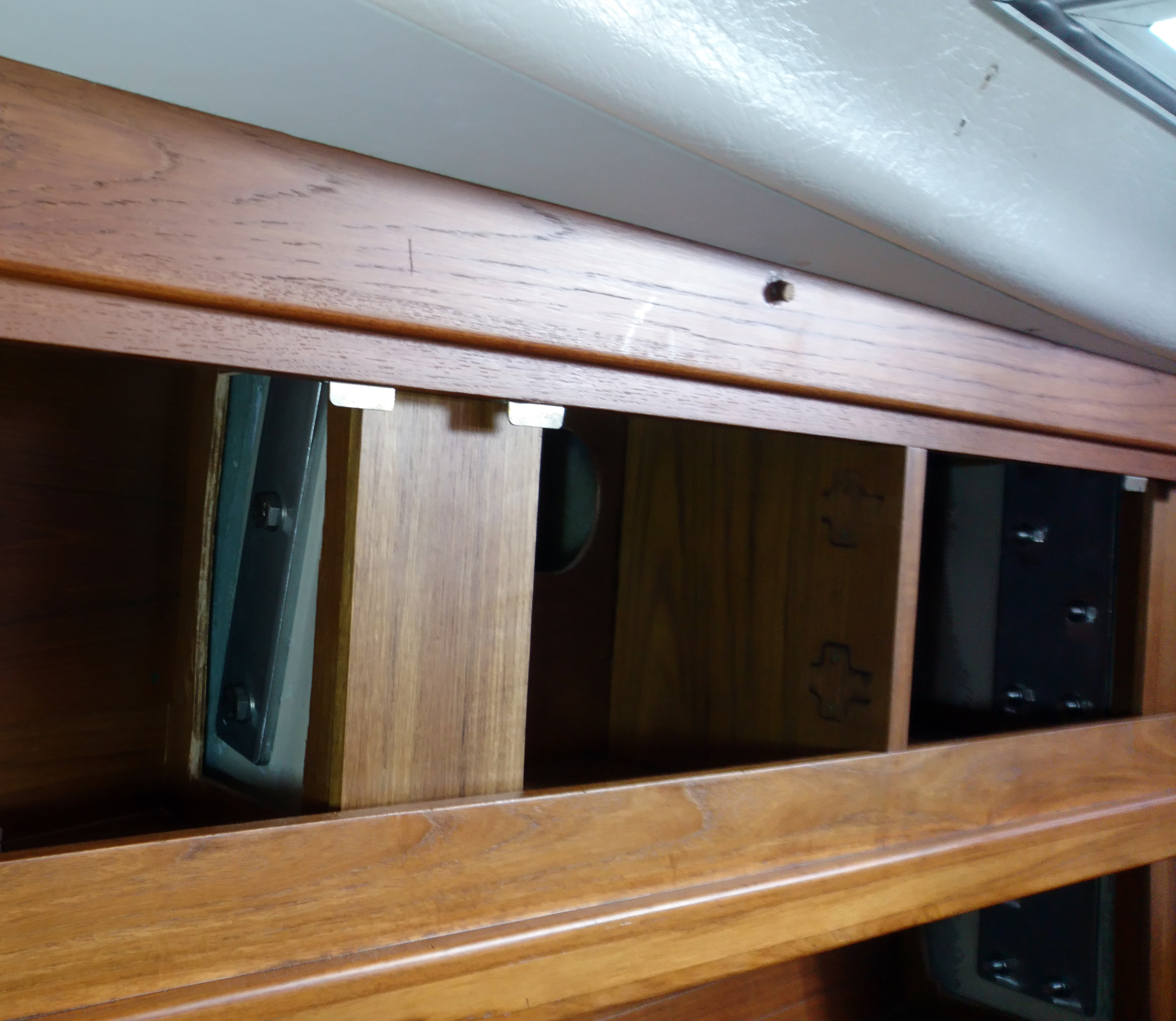
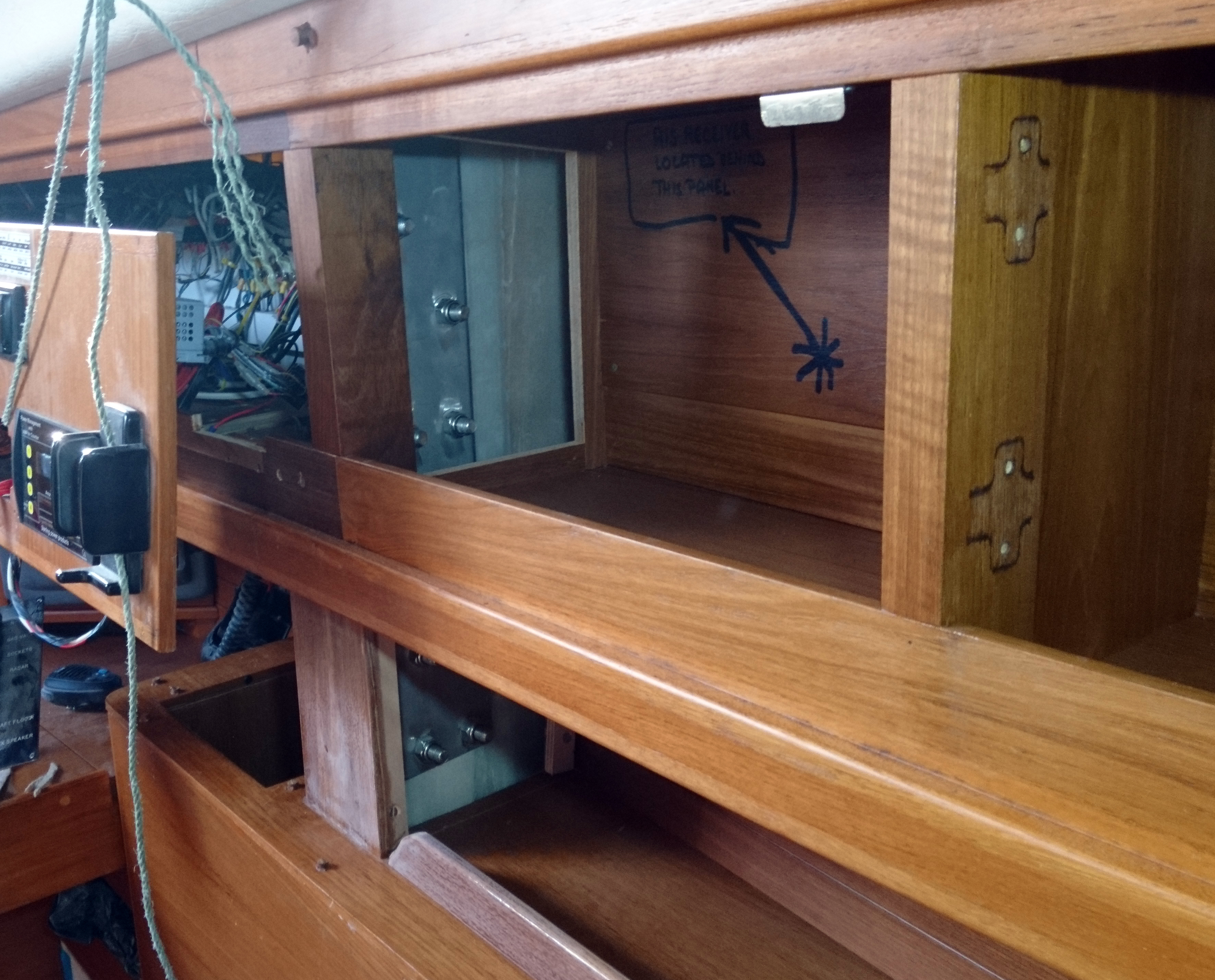
With the tank in place we ensured there was space above to allow a tank level sender unit and breather filter and allow access so that the carbon cartridge can be changed. The flush and pump out fittings and pipework are hidden behind the fibreglass panel on the left but can be reached over the op of the tank if needed.

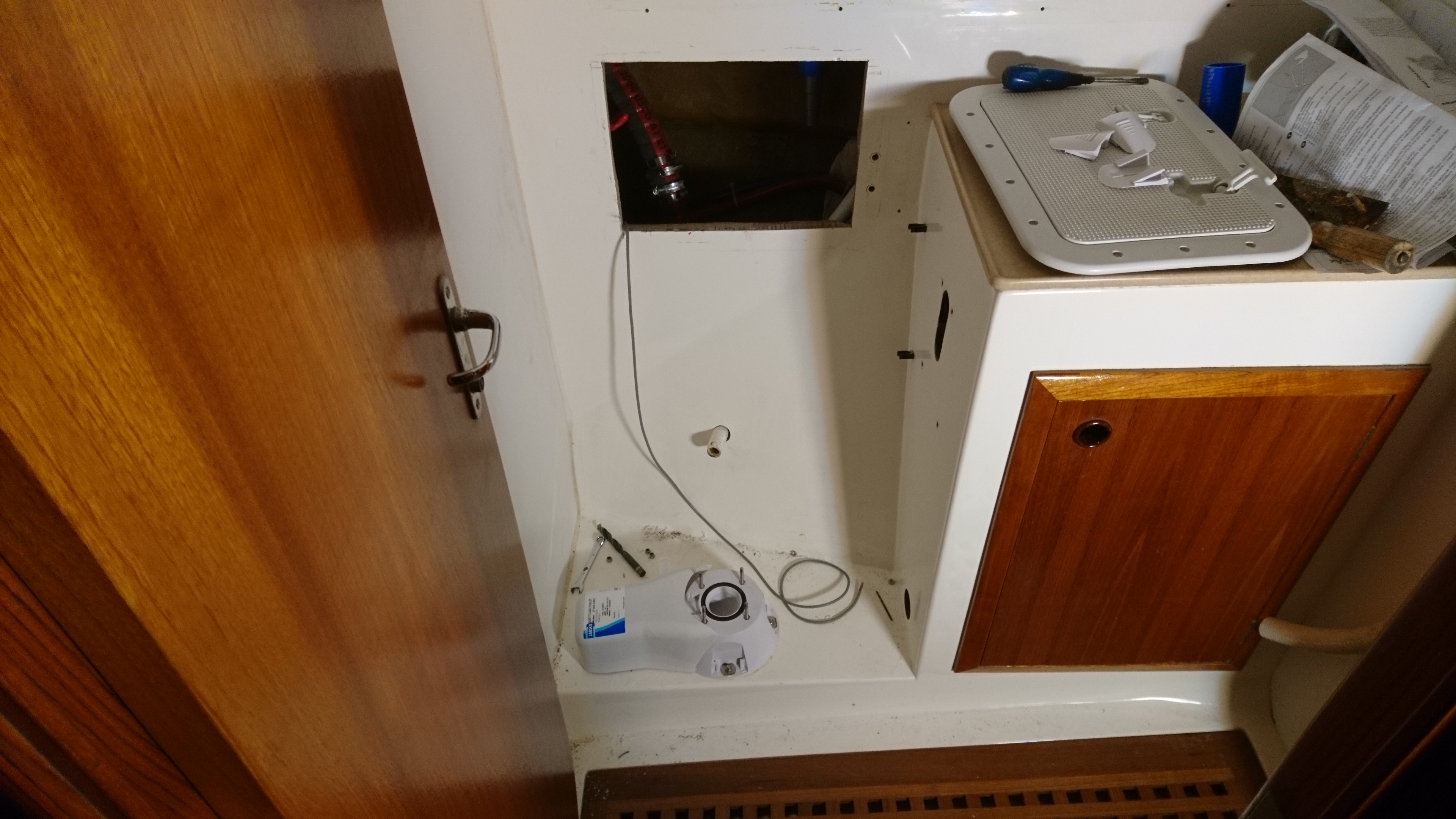
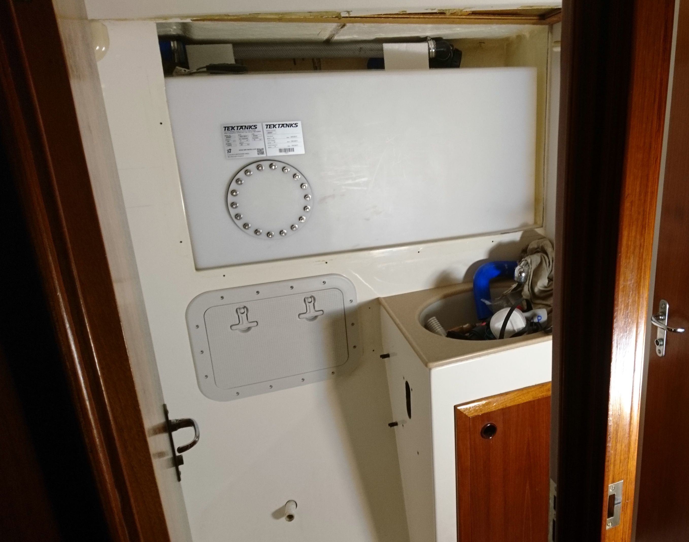
Below the tank we fitted a hatch cover to give access to the bottom of the tank and to the three way Jabsco diverter valve.

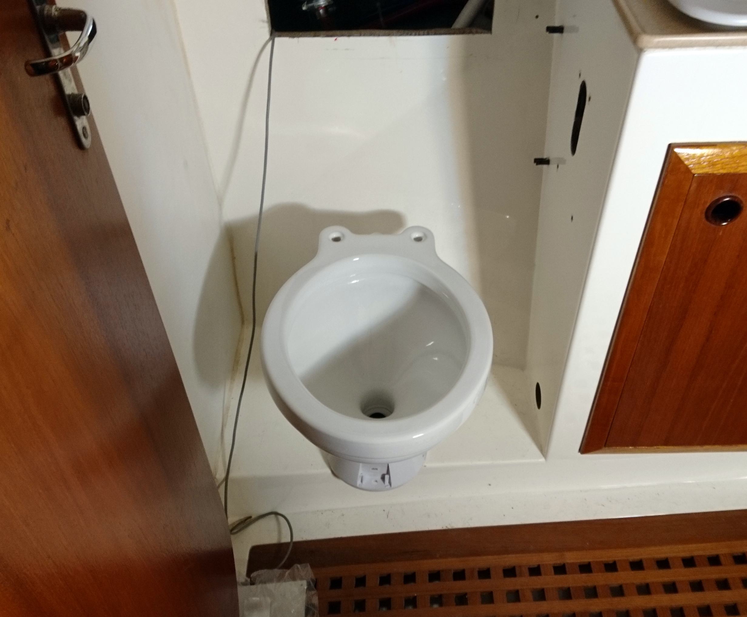
We also took the opportunity to fit a new electric loo.

The trim and doors back on ensuring that everything can be dismantled to get full access to the tank in the future.

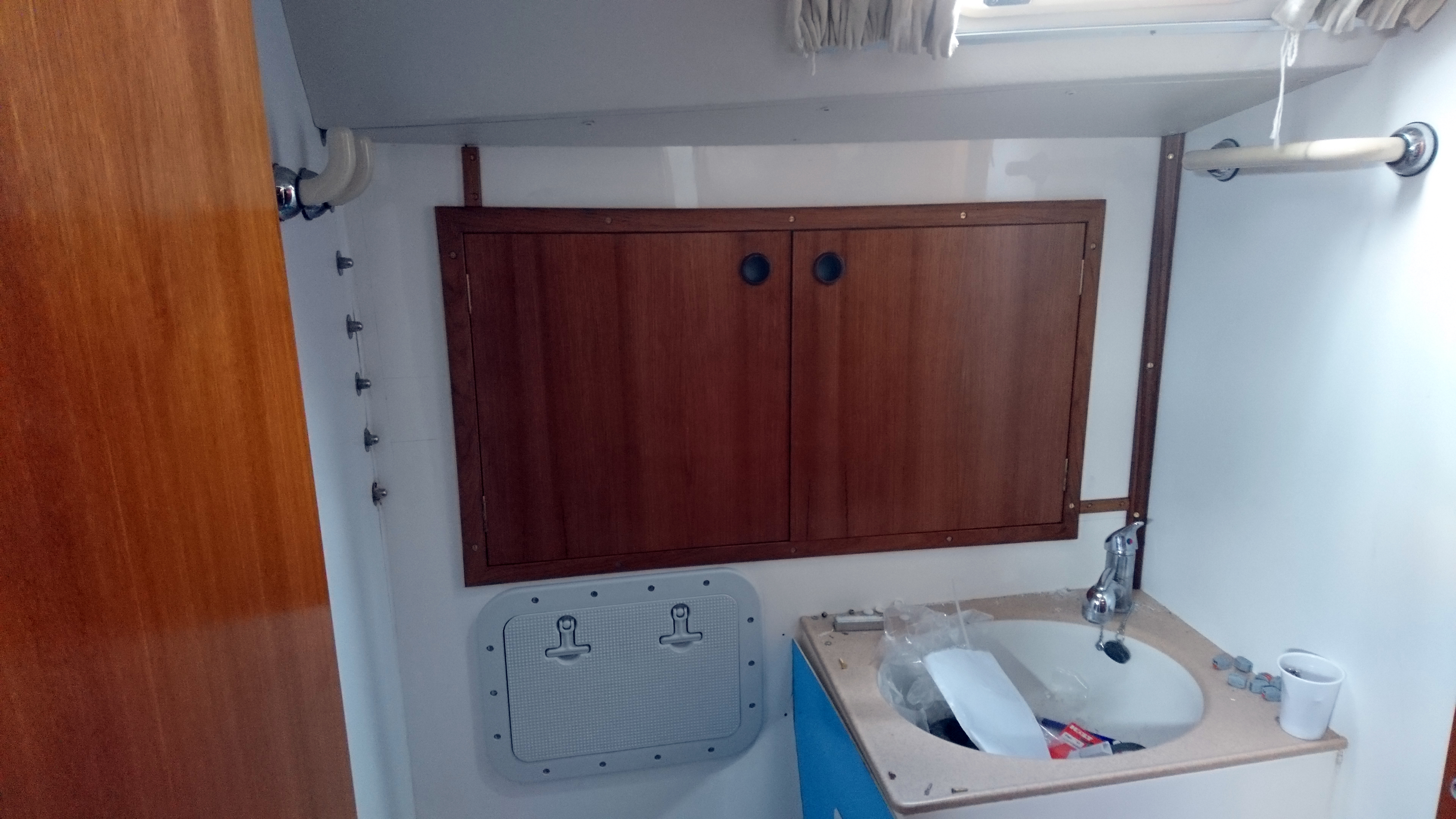
The owners will have to find a new place for their tooth brushes.

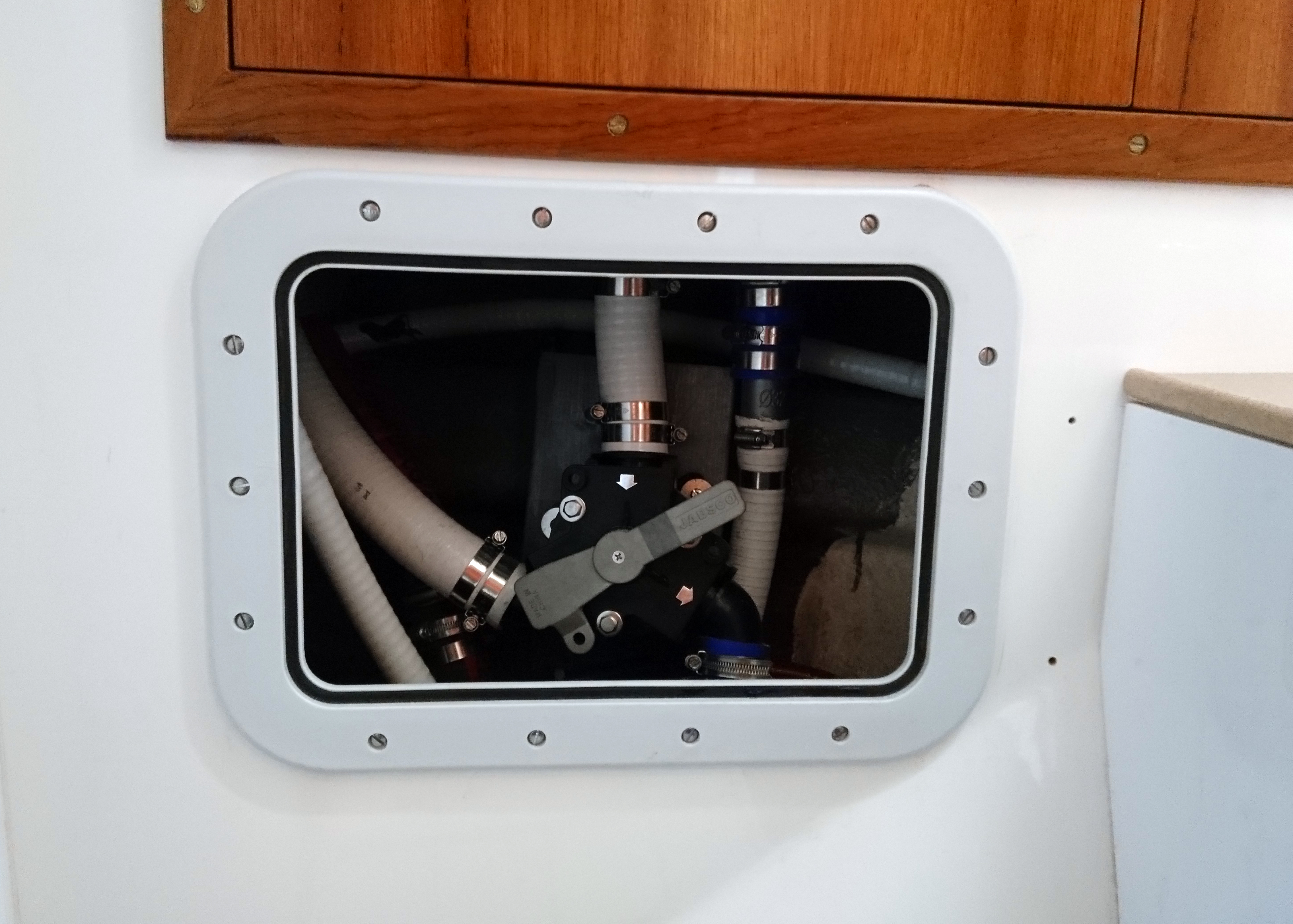
The hatch above the loo gives access to all the pipework and the excellent Jabsco three way valve which has clever adjustable hose fittings that accommodate irregular pipe angles.

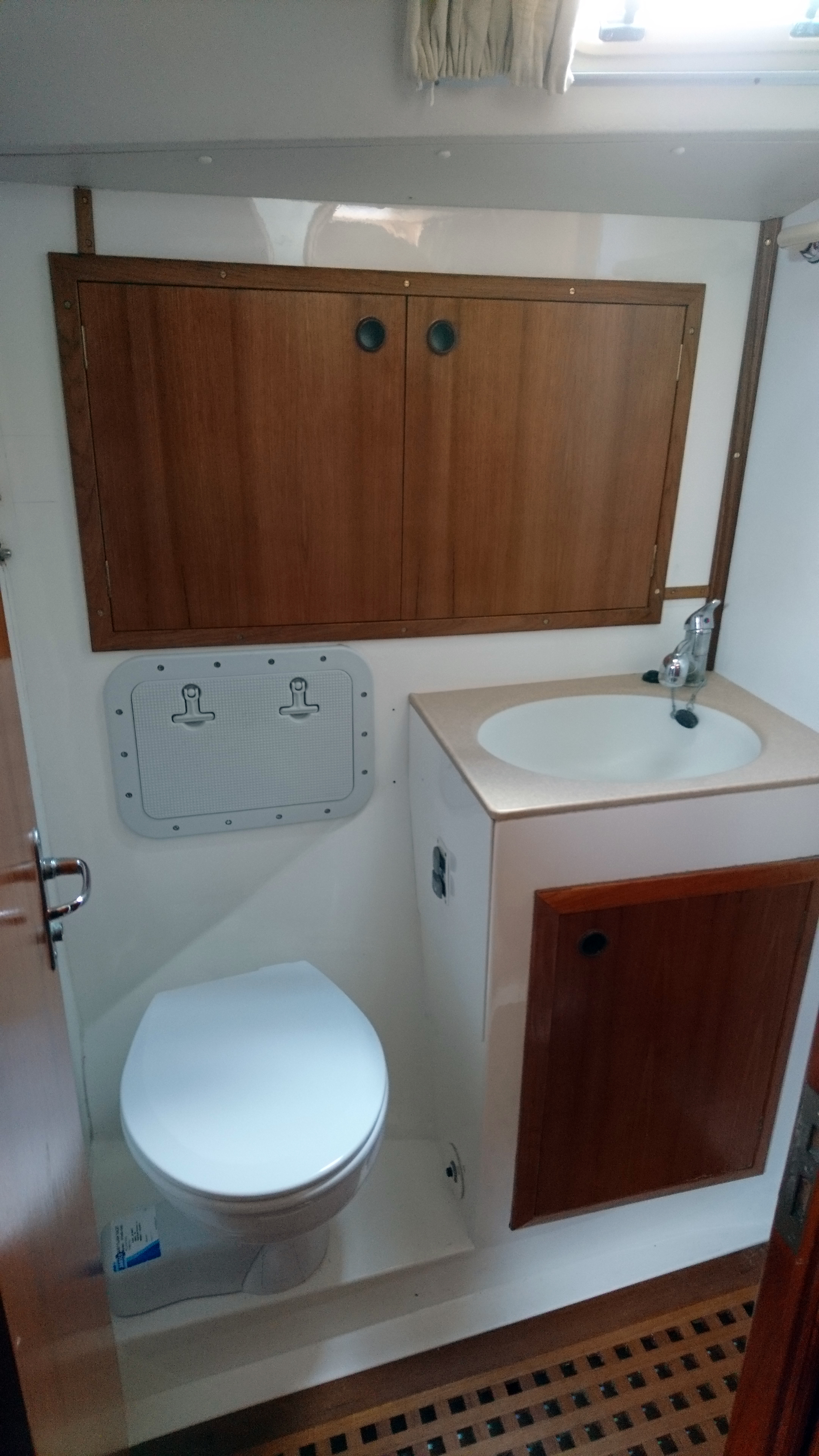
Apart from the extra little bits of trim and the viable fasteners to enable easy access the look of the heads is largely the same as before.

By | 2019-10-06T01:01:45+01:00 March 30th, 2017|Uncategorised|Comments Off on Holding tank

Deadwood fairing

Small project to fair in the deadwood on a Colvic Watson and installation of a smaller prop

Updated – 20/3/17

We recently carried out an engine change on a Colvic Watson. All went well, however the original huge prop has now become a little too huge when under power.
In gear at tick over the North Sea visibly increases speed through the Dover straits and the new engine would only rev to around 1500.
So we need to reduce size of the prop and possibly increase the pitch.
On the positive side reducing the size will reduce sailing drag but there isn’t enough in the owners budget to stretch for a feathering or folding prop.
There’s no doubt that a big three bladed prop causes drag, especially one coupled to a hydraulic gearbox that cannot be left to freewheel and a smaller prop will cause less drag but the danger of reducing the prop size on this design is that so much of the prop is hidden in the shadow of the keel. 
We could keep the prop the same size and just increase the pitch but the owners like to sail so improving efficiency by reducing drag is the best option and given the budget constraints a smaller prop is the way to go.
So the task is to improve the flow round the back of the keel and give the smaller prop half a chance and at the same time it will vastly improve the flow over the rudder.

The initial plan of a short fairing just didn’t look or feel right to me.
My rule of thumb is to look at an underwater obstruction and times the size by 3 to gain an idea of when the flow might start to get itself sorted out.
So a 5″ wide trailing edge will be casting a shadow at least 15″ aft.
There’s no way I can get 15″ of fairing so I’m just working on getting as much as I can.
A few more chunks of celotex and a glue gun gave me something to work with to get a reasonable shape.
I shaped it by eye rather than spending a lot of time making templates which kept the costs down.
A good 10″ of existing keel was ground back to provide a good key and anchor for the fairing.
The keel and foam was then tied together with a four layers of 450g chopped strand mat and polyester resin.
Three layers of gelcoat was then applied and a final coat of gelcoat with added Wax in Styrene which acts as a top coat.

Whilst a great gelcoat finish isn’t really required in an area soon to be covered in layers of primer and antifoul I advise you still apply multiple thin layers of gelcoat rather than slapping on a thick coat.
The issue is that during the mixing phase you will inevitably introduce air into the mix.
Applying the gelcoat in a thick layer will trap these tiny air bubbles which can make the gelcoat porous and if you cut back to get a really shiny finish you will get tens of tiny holes that are impossible to fill. Cutting back more just exposes more holes and so on.

Gelcoat will not cure in air, it gels and stays sticky.
When applied to a mold and then glassed over the air is eliminated and the gelcoat will set hard.
So when applying on top of glass without a mold we need to eliminate the air somehow.
To do this we add wax in styrene in roughly the same quantity as you add the catalyst.
During the curing process the wax comes to the surface effectively sealing the gelcoat from the air and allowing the gelcoat to set hard.
It should be noted that if you need to add any additional layers of gelcoat you will need to remove this wax by keying well with wet and dry sand paper or similar.

Once completed our sea trail proved we had chosen the right size prop as the boat top speed is unchanged but the engine now revs to 2500.
The biggest change was at slow speeds where the slow handling has been transformed for the better.
We await reports back from the owners on sailing performance.
Next time she’s out of the water I need to convince the owners that the barn door they use for steering needs some matching hydrodynamic help.


The trailing edge of the Colvic Watson is not the mostt hydro dynamically friendly design.

The direct shadow caused by the trailing edge of the keel over the old, huge prop.
The new smaller prop would struggle.

Initial plan was for a small fairing using a foam core.

I decided that it simply wasn’t enough so the fairing grew.

and grew…..

Final shape with prop temporarily fitted to check clearance ready for gelcoat.

After three coats of gelcoat and one coat of topcoat or flowcoat gelcoat. (essentially gelcoat with added wax)

A coat of International Primocon and then a couple of coats of Seajet antifoul, shes ready for the water.

By | 2017-05-03T23:24:23+01:00 March 20th, 2017|Uncategorised|Comments Off on Deadwood fairing

Dodgy knees and soggy decks

Job finished. Update – 03/5/17


Looking around the yard, I notice that of the nine boats being worked on today, the youngest boat is over 10 years old and the oldest is 80 years old.
The majority are between 15 and 30 years old, and 28ft and 60ft in length. Predictably the three oldest are wooden, the five grp boats are all in the 18-30 club and youngest of our current crop is a 57ft’ foot aluminium, iceberg chasing, ketch.
Most are in the yard for several reasons: three are having new engines, three are having new decks, two are having new chain plate knees  and bulkheads, two are having new ? (water, diesel?) tanks,  two are undergoing full restoration and one has finished her full restoration and is now floating and having the finishing touches made before returning to her owner.

So many times the cause of a restoration starts with leaking decks. Modern boats suffer the same fate as well. Two boats currently  in for new knees and chain plates were also because of leaking decks, a  57ft aluminium ketch is in because its teak deck had lifted and the aft deck of a Colvic Watson is undergoing strengthening surgery and curing some, you guessed it, leaks in the deck.

I’d argue that fresh water is a far bigger evil than the salty stuff, in terms of keeping you afloat.

If you don’t keep a close eye on through deck fittings by the time you see evidence the damage has already started.
The biggest culprits are window frames. genoa tracks, stanchion bases and through deck chain plates.
The first place for water to explore once past failed sealant is the deck core.
The core is usually balsa, foam or plywood or a mixture.
If its wood its obvious what will happen over time, with foam you might be lucky although water will encourage delimination of the deck upper and/or lower skin from the core and slowly spread.
The next place for water to reach will be the back of headlining or trim that covers the entry point.
The water can travel a long way before emerging as a drip usually on the back of your neck whilst trying to read a chart at the nav station.
The danger is that in the case of chain plates, water will get between the chain plate and the knee or bulkhead it’s attached to.
It will then travel along the bolts and start to soak the wood, that is usually encapsulated in grp, which now essentially turns into an unhelpful bucket.
The wood rots and the chain plate will lift, usually raising the deck in the area before eventually failing resulting in a lost rig or worse.
Obviously this wont happen over night but most of us are sailing in boats over 10 years old and that’s enough time for this to become an issue.
We have two boats in their 20’s at the yard with this problem, severe enough to mean cutting out the old knees and replacing them.

If you’re worried but can’t see any evidence see if you can get hold of a moisture meter which often gives you a heads up. 
If you suspect water has got in then you’ll need to dig further.
We remove the chain plates which allowed us to have a good poke at the core with something pokey.
On the Pasport 40 the core was pretty good, damp but still firm with no obvious signs of damage.
On the moody however the plywood core was wet and rotten and needed to be cut out around the chain plate slot and the old cover plate fixing screw holes, it also extended aft and outward a few inches from the slot which follows the fall of the deck.
Down below it was a different story on the Passport 40 with the inside of the Knees saturated, the wood turned to mush.
Water had even got between the knee laminate and the hull and on removal we saw at least a couple of cupfuls of brown water drain down into the bilge.
On the moody we drilled out a core from the knee around 3ft below the deck.
The moisture meter was not happy even three feet down from the entry point and whilst not soaking it was bad enough to condemn the knees especially considering the poor design of the chain plates.

Repairing the deck on the Moody could have been done from inside but given we were going to redesign the chainplate and incorporate a sealed top plate which would cover the repair, it was decided to repair from the top which is a whole lot easier to do saving time and money.
So first we cut away the top deck laminate to gain access to the core.
The best tool for this and one of the most useful tools in the yard is the Oscillating Multi-tool in both 240v and 18v battery versions.
The blades are horrendously expensive but if you’re paying £30 an hour for me to do this and it takes less than half the time than using a chisel then it makes sense.

Once the wet core is removed and you’re back to solid wood then its time for a heat lamp for a day or so to get the moisture content down and give the epoxy half a chance to work its magic.
When dry, we tape up the chain plate slot below decks and coat the exposed edge of the core with warmed up epoxy.
Warming thins out the epoxy and it will soak in better but shortens working time so keep the batches small.
Before this has time to go off we build back up to original deck level with epoxy and glass cloth.
I used a couple of layers of powder bound csm (Powder bound csm is specifically designed for use with epoxy you should never use normal emulsion bound csm with epoxy) and then layers of 300gm and 450gm biaxial cloth.
I like to use the csm (chopped strand mat) initially as I believe I get a better initial bond and its easier to manipulate to ensure I get coverage over the edge of the core material.

Below decks things are about to get really very messy.
Cutting old grp is bad enough and the knees will come off pretty easily with the multi-tool.
Grinding back to good clean laminate so we have something nice to epoxy too is a different matter.
The dust gets everywhere and I mean everywhere.
Plastic sheets and masking tape covering everything you can see, floor, roof, bunks everything and even then there will be a dusting of white powder in the aft cabin locker under the bed!
We normally encourage owners to come in help and especially carry out some of the mundane tasks as it saves them money.
I’m not sure I’d like to pay someone to drive a vacuum cleaner at yard rates but sometimes there is no choice.
Once the inside of the hull is nicely keyed and most of the dust is sucked away we can bond in the new plywood knees.
We use the old knees as patterns and bond in the new ones on thickened West epoxy using 404 high density filler to bed on and 406 colloidal silica for filleting.
Once this has gone off we abrade the fillet to remove any blush and round off the inside edge of the knee as glass cloth does not like going round sharp corners, then we can start to sheath the knee.
This soaks up time and it can take a full day to glass in a full height knee.
Its important that you try and get it all done in one go so you don’t have to go through the removal of the amine blush which happens during the epoxy curing process.
You could use a product called peel ply which avoids this issue though its not cheap and for intricate shapes can be a pain to use.
Another issue with epoxy is unlike polyester resin you can’t afford to mix up too much resin at a time for fear of it exotherming (going off) especially if you warm the epoxy to reduce its viscosity to aid wetting out the glass.
So I tend to mix up a maximum of 8 pumps at a time.
Coating the whole area first I lay up two layers of 250g powder bound csm followed by 4 layers of 300g biaxial cloth.
That essentially seals and sheaths the knee.
I then start adding the tabling which is the main laminate that joins the hull to the knee.
Using lengths of 150mm wide 450g biaxial cloth I lay up 6 layers starting with around 125mm on the hull and 25mm on the knee and then overlapping by around 25mm each time, ending up with 125mm on the knee and 25mm on the hull.
The area that will take the loading from the chain plate gets additional layers, taking into account the direction of stress.

Once cured the position of the chain plate bolts can be marked.
Before finalising the positions of the bolts check that there will be access when the interior woodwork is put back in place so that you can carry out regular inspection and future re-sealing if required.
Ensure that if the knees are used in the mounting of the interior trim at any holes made by screws are suitably sealed.
Once happy, core drill the bolt positions out to 25mm diameter.
You can check each core plug to check laminate thickness and see how well each has bonded and whether I’m any good at laminating.
Tape up on side of each hole and coat the bare wood with neat epoxy followed by filling each hole carefully with a thick epoxy high density mix. I use a syringe for this usually but you need to ensure all the air escapes otherwise you can get a void which will need to filled afterwards.
When this has set we can re-drill the final bolt holes, in this case at 12mm.
The chain plates can now be fitted, either bedded down on a suitable sealant or a epoxy silica mix.
These repairs should be good for another 25 years at least, though fresh water has a horrible way of finding its way in.
So don’t ignore the soggy tide tables, investigate why before it attacks something else.

Typical modern deck with multiple through deck fittings.

Removal of the fitting will allow access so the immediate area of the core can be inspected.

After identifying water ingress the choice is to either cut it out below decks or in this case, above decks.

Deck skin removed on Passport 40. The dark wood is wet the rest is damp. Note the poorly cut out slots for the chain plates by the original builder.

The damaged core can be removed without damage to the inner skin.
Assessment can then be made to the extent of the core damage.

Top layer and soggy core removed

Passport 40, chain plate sections removed ready for drying out and filling/glassing with Epoxy

Seal the dry core edge with neat epoxy, then fill with thickened epoxy if necessary before laying up with epoxy/glass.

Continue to add glass until just proud of the deck and sand back flush. Be careful not to sand away any non-slip from the surrounding area.

After time, water leaking into a knee will turn the wood into mush leaving just the outer shell which has little shear strength and certainly will not stand up to significant rig loads.

Down below discoloration in the knees laminate and more obvious water stains from the chain plate bolts are a sure sign of trouble.

To track the extent of any damage a core can be drilled out lower down the knee and inspected using a moisture meter if no obvious signs exist.

If the damage is irreparable there’s no option other than to cut the old knees out.

With the knee removed you can see if any other horrors lurk in the background.

Can’t avoid this, it has to be done. grinding and sanding the interior ready to take the new knees.
The dust this creates in truly unbelievable, but you must not skip this task.

New plywood knees are bonded to the hull on thickened epoxy.

After 2 layers of 300g powder bound csm the first of 4 layers of 300g bi-axial cloth can be applied.

6 staggered layers of 450g bi-axial tape on each side of the knee.

High stress areas have additional layers of 450g bi-axial cloth. 

TOP TIP – If you don’t have time to layup in one day use a layer of peel ply.
When you are ready to complete simply peel off the the peel ply and the surface will be ready for the next layers.

Once mounting bolt locations are identified, 25mm cores are drilled out.

The cores can be inspected for laminate thickness and consolidation.

The bare ply in the cored holes needs to be coated with epoxy.

The cores are then filled with thickened epoxy.

The m12 final holes for the chain plate will have at least 10mm of epoxy silica colloidal around the bolt.

The cabinets were modified to enable easy access to chain plates in future.

Matching wooden blanking plates will be inserted and screwed in place.

With easy access it will be easy to monitor any water ingress in future.

By | 2017-05-03T22:58:36+01:00 March 7th, 2017|Uncategorised|Comments Off on Dodgy knees and soggy decks